Practical Re-Write Codes with Access Considerations Yuval Cassuto Technion – Israel Institute of Technology Department of Electrical Engineering
[email protected]
Eitan Yaakobi University of California, San Diego California Institute of Technology Electrical and Computer Engineering Electrical Engineering
[email protected]
Abstract— We present new codes that allow data rewriting without physical erase on multi-level cell technologies. The codes are practical as they use a small number (e.g. 2) of cells, and allow data bits with different update characteristics (hot vs. cold).
I. Introduction Flash storage media offer remarkable densities that enable their ubiquitous use in numerous consumer and enterprise storage products. Densities of such scale introduce restrictions on the way data can be accessed on the device. The most apparent and well-studied feature of flash access is the inability to perform erase operations at the cell or page level, but only in much larger units called flash blocks. The coarse granularity of erase operations together with their significant time and wear costs require careful control of the write access to the physical cells by upper layers of the storage device. To mitigate this access limitation, a flash translation layer (FTL) was introduced to solid-state drives, with the objective to dynamically optimize the physical placement of data. As an alternative to placement optimization, lower level frameworks have been proposed for data representations that improve the access capabilities of the device [5]. One model that was found particularly relevant to the properties of flash storage is the write-once memory (WOM), first proposed by Rivest and Shamir for a different application [7]. The applicability of the WOM model to emerging solid-state storage technologies have sparked a renewed interest, and has led to significant research progress in recent years, e.g. [3], [6], [8]. The main idea in the WOM and related frameworks is to encode the user data in a way that unrestricted updates will be possible without need to physically erase the storage cells. This capability allows rewriting data in place without incurring the wear and time-overhead of block erases after every write. In particular, the original binary WOM model [7] treats codes that allow writing k bits t times using n physical bits that are only allowed to move from 0 to 1. The great promise of the WOM model is that t writes of k bits do not actually require n = kt physical bits, but potentially as little as n = kt/ log2 t (for large t). This promise, however, does not come without challenges. Some of these challenges are now listed. 1) Efficient WOM constructions often have a different k for each of the t writes. This property is hard to accommodate in practice. 2) Long representations with little structure mean exponentially growing decoding complexities. 3) The generalization of binary WOM codes for multi-level cell technologies is not well established yet. 4) The known models assume that all user bits have the same access characteristics, and therefore may be wasteful in redundancy.
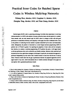
These challenges are the main motivators to the current work, which addresses the challenges above as follows: 1) Fixed k number of bits in each of the t writes is sought by all constructions. 2) Small numbers (i.e. 1 or 2) of cells are used to encode data. 3) The proposed WOM codes are tailored to multi-level cell technologies by using the q-ary generalization of the model. 4) The codes distinguish between “hot” and “cold” bits in the number of updates they allow (hot bits are updated frequently, cold bits are updated rarely). Jointly storing hot and cold data provides automatic wear leveling without need to waste erase cycles on moving cold data across physical locations. We now open the presentation with concrete details on the model. Then in the following sections sample constructions will be presented. Given n physical cells with q discrete levels, we wish to store k information bits in a way that the information can be written t times without moving a physical cell to a lower level. Each of the t writes is called a write generation. Any of the 2k possible values can be assigned to the k information bits at any given write generation. A scheme that supports the above properties will be called a (q, n, k, t) re-write code. This model was studied in [1] and later in [2] as a generalization of Rivest and Shamir’s binary WOM [7]. As opposed to previous works, here we are mostly interested in the case where the number of cells n is small. A related problem, where in each write only one bit out of the k information bits is updated, was proposed in [4], and solved optimally for the special case k = 2. To support the large data units used in NAND flash storage we note that if a (q, n, k, t) re-write code exists, then there also exists a (q, nM, kM, t) code by trivially using M independent copies of the code in parallel. In Section II we present (q, n, k, t) constructions for fixed small k and n, and t that depends on q. Then in Section III we give sample codes that break k into k1 hot bits and k2 cold bits, allowing up to a single write to each cold bit out of the total t writes. II. Re-write Codes with n = 2 Physical Cells In an n = 2 code, the physical content of the memory is described by a pair (c1 , c2 ) ∈ {0, . . . , q − 1}2 of cell levels. The information content is represented by an integer number v ∈ {0, 1, . . . , 2k − 1} = {0, 1, . . . , 7} (for k = 3), and a mapping between integers and k-bit vectors is implicitly assumed. Reading information is then performed by a function ψ(c1 , c2 ), where ψ : {0, . . . , q − 1}2 → {0, 1, . . . , 7}. Writing k bits to the physical cells is specified as a function µ : {0, . . . , q − 1}2 × {0, 1, . . . , 7} → {0, . . . , q − 1}2 of the current cell contents and the new information integer. Thus,
µ(c1 , c2 , v′ ) = (c′1 , c′2 ), where > > c2 . Such read and write functions for k = 3 are specified in Figure 1. The numbers inside the matrix stand for information integers in {0, 1, . . . , 7}. The coordinates marked at the exterior of the matrix represent cell levels. The horizontal coordinate is c1 and the vertical one is c2 . The reading function ψ(c1 , c2 ) is simply the content of the (c1 , c2 ) position of the matrix. A write function µ(c1 , c2 , v′ ) can be obtained from Figure 1 by defining (c′1 , c′2 ) to be the nearest (different) position that contains the number v′ , such that c′1 > c1 and c′2 > c2 . For example, suppose the current cell levels are (c1 , c2 ) = (0, 2), storing the integer 4. Then a value v′ = 7 is written by moving the cells to levels (c′1 , c′2 ) = (4, 3). Each c′1
c1 , c′2
write#1
7 6 5 4 3 2 1 0
write#2
write#3
4
3
7
2
5
4
6
0
1
3
7
2
5
4
6
0
1
3
7
0
2
5
6
1
0 1 2 3 4 5 6 7 Figure 1.
A code to store 3 bits in 2 cells with t = (q − 1)/2 writes.
polygon of area 8 in Figure 1 specifies the range of possible cell levels (c′1 , c′2 ) after a given write generation. Note that if the write generation is known at the time of writing v′ , there is no need to read the current cell levels (c1 , c2 ) prior to writing, since the target levels (c′1 , c′2 ) can be extracted directly from the corresponding polygon in Figure 1. It turns out that it is possible to improve the t = ⌊(q − 1)/2⌋ result to t = ⌊4(q − 1)/7⌋ by a more clever update rule than was used in Figure 1. III. Rewrite Codes for Hot/Cold Data The codes in this section treat hot data (for example filesystem logs) and cold data (such as archived documents or photos) differently. Hot and cold bits share the same physical cells and therefore provide wear leveling at the physical layer. To see the general idea, we start with a simple example. Suppose we want to store one hot bit and one cold bit. Hot bits, as before, can be written multiple times without erase, while cold bits are written only once between physical erasures. Both hot and cold bits can be read at any desired time. A level diagram for these requirements is found in Figure 2. The two stored information bits appear at the bottom of the figure, the right of which (underlined) is the hot bit. Solid arrow lines represent changes in the hot bit, and dashed arrow lines represent re-writing the same value for the hot bit. write #3
4
6
5
7
write #2
4
2
5
3
write #1
0
2
1
3
00
01
10
11
Code to store 1 hot bit and 1 cold bit in 1 cell with ⌊q/2⌋ total writes.
Figure 2.
Restricting the cold bit to up to one write allows a total number of writes that equals t = ⌊q/2⌋ (including the one cold
write). This is an improvement from an n = 1, k = 2 re-write code that gives only t = ⌊(q − 1)/3⌋ writes. Note that the t − 1 writes of the hot bit and the single write of the cold bit can be performed in any order. For example, if the hot bit is written multiple times before the cold bit’s write, we initially use the left part of the diagram (even levels) to update the hot bit, and in case of a ′ 1′ write to the cold bit, we can always move to the corresponding state at the right part of the diagram (odd levels), which only moves the cell level upwards. The code of Figure 2 turns out to be optimal. A. Two-cell hot+cold bit storage We now detail a two-cell code to jointly store one hot and one cold bit. We start with specifying the decoding rule pictorially in Figure 3. As in the two-cell codes of the previous section, the coordinates at the exterior of the matrix represent physical-cell levels, and the integers within the matrix are the information content of the stored bits: 0 stands for 00, 1 stands for 01, 2 stands for 10 and 3 stands for 11. The underlined bits are the hot bits that can change multiple times in the write sequence. The non-underlined bits are cold bits that can be written once, at any point of the write sequence. To support unrestricted re-writing of the hot bit, the following transitions must be possible without decrease in physical-cell levels: 0 → {0, 1}, , 1 → {0, 1}, , 2 → {2, 3}, , 3 → {2, 3}, In addition, a single transition of the form 0 → 2 or 1 → 3 must be supported. The code described above turns out to be 4 3
3
2
3
2
1 0
2
3
2
1
1
2
1
0
0
1
0
0
1
2
0
3
4
Decoding rule for a scheme to store 1 hot bit and 1 cold bit in 2 cells with t = 2q − 3 writes, at most 1 of which is a cold-bit write. Figure 3.
strictly optimal. Other codes we found support multiple hot and/or multiple cold bits. Due to lack of space we cannot describe them in this written summary. References [1] A. Fiat and A. Shamir, “Generalized write-once memories,” IEEE Transactions on Information Theory, vol. 30, pp. 470–480, 1984. [2] F. Fu and A.J. Han Vinck, “On the capacity of generalized write-once memory with state transitions described by an arbitrary directed acyclic graph,” IEEE Trans. Inform. Theory, vol. 45, no. 1, pp. 308–313, September 1999. [3] R. Gabrys and L. Dolecek, “Characterizing capacity achieving write once memory codes for multilevel flash memories,” Proc. IEEE Int. Symp. Inform. Theory, pp. 2484–2488, St. Petersburg, Russia, August 2011. [4] A. Jiang, V. Bohossian, and J. Bruck, “Rewriting codes for joint information storage in flash memories,” IEEE Transactions on Information Theory, vol. 56, no. 10, pp. 5300–5313, 2010. [5] A. Jiang and J. Bruck, “Data representation for flash memories,” in Data Storage, In-Tech Publisher, 2010. [6] S. Kayser, E. Yaakobi, P.H. Siegel, A. Vardy, and J.K. Wolf, “Multiplewrite WOM-codes,” Proc. 48-th Annual Allerton Conference on Communication, Control and Computing, Monticello, IL, September 2010. [7] R. L. Rivest and A. Shamir, “How to reuse a write-once memory,” Information and Control, vol. 55, no. 1, pp. 1–19, 1982. [8] Y. Wu and A. Jiang, “Position modulation code for rewriting write-once memories,” IEEE Transactions on Information Theory, vol. 57, no. 6, pp. 3692–3697, June 2011.