Predicting Charge Roller Performance in Electrophotography Using Electrostatic Charge Decay Measurements
Ming-Kai Tse, David J. Forrest and Francis Y. Wong QEA, Inc. 755 Middlesex Turnpike, Unit 3, Billerica MA 01821 USA Tel: (978) 528-2034 · Fax: (978) 528-2033 e-mail:
[email protected] URL: www.qea.com
Paper presented at the IS&T’s Eleventh International Congress on Advances in Non-Impact Printing Technologies, Oct 29-Nov 3, 1995, Hilton Head, South Carolina
Predicting Charge Roller Performance in Electrophotography Using Electrostatic Charge Decay Measurements Ming-Kai Tse, David J. Forrest and Francis Y. Wong Quality Engineering Associates, Inc. Burlington, MA 01803 USA Abstract Contact charge rollers are used extensively in electrophotographic printers and copiers to minimize ozone emission and to improve charging efficiency. It is well known that the surface electrical properties of a charge roller critically determine the effectiveness of the charging processes. For example, a low surface resistance may lead to destructive arcing to the photoreceptor, and a high surface resistance may result in under-charging or nonuniform charging of the photoreceptor. In this paper, a novel electrostatic charge decay (ECD) technique, which provides non-contact and nondestructive measurements on surface electrical properties, is examined to assess its ability to predict the performance of a charge roller. The principle behind the ECD technique and the supporting evidence for its efficacy will be discussed.
Introduction Primary charge rollers (PCR) are used in many electrophotographic printers and copiers to charge the organic photoconductor (OPC). The mechanism of the charging process is generally understood to be ionization of 1-3 air in the gap between the PCR and the OPC, which depends on the voltage difference between the two. If the PCR resistance (or more accurately, the impedance) is too high, the voltage drop across the PCR increases, thus lowering the voltage difference across the air gap and 4 reducing the ionization and the charge level on the OPC. On the other hand, if the PCR resistance is too low, the maximum current through the PCR and the air gap is not limited. In case a defective OPC is used in conjunction with such a PCR inadvertently, a black line may develop across the printed page due to excessive loading of the PCR power supply. Further damage to the OPC may also result due to rapid and energetic discharge into the OPC in some cases. Since the PCR resistance strongly determines OPC charging efficiency and directly affects print quality, its quality must therefore be measured and controlled in the
manufacture of PCR. Simple resistance measurements by applying a small voltage and measuring the current may not be appropriate because in operation, the PCR is subjected to high voltage levels including an AC component. In this study, a computer-controlled test system (CRT-2000, Quality Engineering Associates, Inc.) based on a novel 5 electrostatic charge decay (ECD) measurement technique is used to predict PCR performance. The principle of ECD is to deposit a charge on the surface of a material, and monitor the rate at which the charge dissipates (decays) through the material. If the material is modeled as a resistor and a capacitor in parallel, then the surface voltage is given by:
V (t ) = Vo e - t
/
RC
(1)
where V0 is the initial voltage, t is time, R is the resistance and C is the capacitance of the material being tested. Thus, ECD measurements are sensitive to both time and the impedance of the material. In a typical ECD test, the operator of the CRT-2000 test system chooses a fixed time delay at which the residual voltage on the roller is measured so that time is essentially eliminated as a variable in the measurement. As depicted in equation (1), a high impedance material will result in a high residual voltage (and vice versa) in the ECD measurement. Therefore, the ECD technique provides a convenient means to characterize the resistance (impedance) of a PCR for the purpose of predicting its performance. In this study, the primary objective is to establish the correlations between the ECD measurements, PCR resistance, and print quality. Another important motivation and objective in this study is to evaluate if the ECD technique is suitable for assessing the reusability of recycled PCR, or the suitability of new aftermarket PCR. In the growing industry of toner cartridge remanufacturing, it is well known that the recycled PCR is one of the primary causes of failures in remanufactured toner cartridges. Therefore, a reliable quality control technique for PCR is vital to the growth of this industry, particularly in view of the fact that PCR are
used more and more extensively in the new generation of low-to-medium speed laser printers.
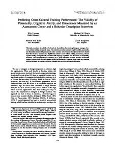
Experimental Method Eighteen primary charge rollers used in Canon’s EX toner cartridge, representing a variety of manufacturers, prior usage histories, and surface treatments (reconditioning) were selected for this study. Since PCR performance is known to be highly sensitive to humidity, the samples studied were conditioned by storing them in a controlled atmosphere at low relative humidity (10% RH or below) prior to all measurements and print testings. This conditioning served two purposes: (1) to eliminate the inconsistent ambient relative humidity as a variable in the testings; and (2) to increase the sensitivity to print quality problems which occur more prominently at low humidity. Three types of tests were conducted on each PCR. First, ECD measurements were made on each PCR using a multitrack scanning technique. Next, the PCR was installed in a modified toner cartridge with an electrostatic probe installed in place of the development roller to monitor the surface potential of the OPC directly in-situ. Since the development roller and the toner were removed from this modified cartridge, no prints were actually made. Finally, each PCR was used in an unmodified cartridge to print multiple copies of several carefully designed test targets for an analysis of the print quality. Electrostatic Charge Decay Measurements ECD measurements were carried out using the CRT2000 system. This system employs a scorotron type corona charger to deposit a negative charge on the surface of a PCR. A non-contact electrostatic voltage probe is then used to measure the residual potential on the roller surface at a fixed time interval following charge deposition. The measurement is analogous to measuring the dark decay in an OPC. A schematic of the test system is shown in Fig. 1. In the ECD measurement, the time interval between charging and measuring was typically 0.25 seconds. A high residual surface voltage at the time of measurement indicates a slow rate of charge decay, corresponding to a high PCR resistance (impedance) and vice versa. Corona Charger PCR
Electrostatic Voltmeter Figure 1. Schematic of the Electrostatic Charge Decay (ECD) Measurement System
OPC Voltage Measurements (in a Modified Toner Cartridge) A standard EX print cartridge was modified so that the voltage on the OPC could be monitored directly in-situ. The set up is schematically illustrated in Fig. 2.
PCR
AC bias DC bias
Laser
Electrostatic Voltmeter OPC
Figure 2. Schematic of an In-situ OPC Voltage Measurement Setup Using a Modified Toner Cartridge
This modified cartridge was used to monitor the OPC voltage while various test patterns were “printed.” By printing a white page with no light exposure, the effectiveness of the PCR in charging the OPC was directly measured. Printing a black page gives a measure of the discharged OPC voltage after PCR charging and full exposure. Printing a gray page (using Postscript) allows measurement of the average OPC voltage over the exposed and unexposed areas. The variation in OPC voltage over an area of solid gray that follows an alternating black and white pattern was measured as an indicator of PCR-induced ghosting. Print Testing Each PCR was also used in a standard cartridge to actually print multiple copies of at least four basic test pages similar to those in the in-situ voltage test above . The first page, which contains an alternating black and white pattern followed by an area of solid gray (50% gray using Postscript), is designed to evaluate the severity of ghosting. The second page is a white page for studying background. The third page, which includes twenty-five squares of different gray density (from 0 to 100%), is used to measure the effect of PCR on print density and tone reproduction. The last page includes different resolution targets to evaluate the degradation of resolution with PCR conditions, if any. Print Quality Analysis An automated image analysis system (IAS-1000, 6 QEA) was used in this study to quantify print quality. The print quality metrics of particular interest in this study include background, ghosting, tone reproduction and resolution as described above under print testing.
750
OPC Voltage (V)
700
650
600 Density = 5
550
Density = 1 500 -180
-160
-140
-120
-100
-80
-60
-40
-20
0
ECD Measurement (V)
Figure 3. Correlation between Directly Measured OPC Voltage in a Modified Toner Cartridge and ECD Measurements in CRT-
2000 Background Ideally, toner is attracted to the discharged areas of the OPC only, and is totally repelled by the charged regions in the discharge area development (DAD) system of a laser printer. In reality, it is inevitable that some unwanted toner may get onto the white area and produces the so called “background” in a print. Background can arise under two types of conditions: 1) if the OPC is not charged up sufficiently to repel all “right sign” (correctly charged) toner; and 2) some “wrong sign” (incorrectly charged) toner exist and are attracted to the oppositely-charged OPC. Fig. 4 shows the correlation between background particle counts
100 90
Particle Count per mm²
Correlation between ECD Measurement on PCR and InSitu Voltage Measurement on OPC Figure 3 illustrates the relationship between the ECD measured in CRT-2000 and the OPC voltage measured in the modified toner cartridge. Note that in this figure, since the charge polarity on the PCR in the CRT-2000 test system is negative, the more negative the ECD reading, the higher the PCR residual voltage. As shown in this figure, the inverse relationship between the two measurements is evident, i.e., a high (more negative) ECD reading corresponds to a low OPC voltage. This observation can be explained on the basis that a high ECD reading reflects a high PCR resistance and a high voltage drop across the PCR. Consequently, the voltage difference between the PCR and the OPC (i.e. the gap voltage), as well as the resulting voltage on the OPC are low. In Figure 3, it is also shown that a print density setting of 5 produces a higher OPC voltage than that at a print density setting of 1. In the printer used in this study (HP Laserjet 4), the DC bias on the PCR increases as the print density setting increases (Density =1, DC bias = -648V; Density = 5, DC bias = -743V), thereby increasing the OPC voltage and producing a darker print.
as measured by the image analysis system and the ECD measurements made on the CRT-2000 system. In this set of data, the background particle count increases with ECD voltage. Since a high (more negative) ECD voltage corresponds to a high PCR resistance and a low OPC voltage (Fig. 3), the high background particle count at the high ECD voltage is therefore more likely due to the inability of an undercharged OPC to repel the “right sign” toner.
80 70 60 50 40 30 20 10 0 -180
-160
-140
-120
-100
-80
-60
-40
-20
0
ECD Measurement (V)
Figure 4. Correlation between Background Particle Counts and ECD Measurements in CRT-2000. Print Density =5.
Ghosting Another common print quality problem associated with PCR charging is ghosting. If a PCR exhibits difficulty in charging up an OPC sufficiently, previously discharged areas on the OPC will have a lower surface potential than its surroundings. Because of the lower surface potential, more toner are attracted to this area, creating a “ghost” image in an otherwise uniform area. Fig. 5a shows a higher variation in OPC voltage (measured by the in-situ technique using the modified toner cartridge) with an increase in ECD voltage. Correspondingly, ghosting (measured in terms of the variation in optical density) is also found to increase as ECD voltage increases (Fig. 5b). 100 OPC Voltage Difference (V)
Results
90 80 70 60 50 40 30 20 10 0 -180
-160
-140
-120
-100
-80
-60
-40
-20
0
ECD Measurement (V)
Figure 5a. Correlation between Ghosting Measured by Variation in OPC Voltage with ECD Measurements in CRT-2000. Print Density = 5.
0.38
0.04
0.36
0.035 Optical Density
0.34
0.03 Density)
Ghosting (Variation in Optical
0.045
0.025 0.02 0.015
0.32 0.3 0.28 0.26
0.01
0.24
0.005
0.22
0 -180 -160
-140 -120
-100
-80
-60
-40
-20
-180
0
-160
-140
-120
-100
-80
-60
-40
-20
0
ECD Measurement (V)
ECD Measurement (V)
Figure 5b. Correlation between Ghosting Measured by Variation in Optical Density with ECD Measurements in CRT-2000. Print Density = 5 .
Figure 6b. Correlation between Optical Density at 10% Gray with ECD Measurements in CRT-2000. Print Density = 5.
1.06 1.04 1.02 Optical Density
Gray Scale and Tone Reproduction The correlation between gray scale and tone reproduction is shown in Figs. 6a-6d. As the ECD voltage increases, the OPC voltage decreases (shown in Fig. 6a) while the optical densities of 10%, 50% and 100% gray (in Figs. 6b-6d) increases. These results were obtained at a print density setting of 5. Similar observations were made at other gray levels and at a print density setting of 1. The optical density measurements in Figs. 6b-6d suggest that a higher PCR resistance will increase the optical density, which is consistent with the observed decrease in OPC voltage as the PCR resistance increases as shown in Fig. 3.
1 0.98 0.96 0.94 0.92 0.9 -180
-160
-140
-120
-100
-80
-60
-40
-20
0
ECD Measurement (V)
Figure 6c. Correlation between Optical Density at 50% Gray with ECD Measurements in CRT-2000. Print Density = 5. 1.43
360 1.41 340 Optical Density
OPC Voltage (V)
1.39 320 300 280 260
1.37 1.35 1.33
240
1.31
220
1.29
200 -180
1.27 -160
-140
-120
-100
-80
-60
-40
-20
0
ECD Measurement (V)
Figure 6a. Correlation between OPC Voltage at 50% Gray with ECD Measurements in CRT-2000.
-180
-160
-140
-120
-100
-80
-60
-40
-20
0
ECD Measurement (V)
Figure 6d. Correlation between Optical Density of Full Black with ECD Measurements in CRT-2000. Print Density = 5.
Contrast Potential and Resolution The difference between the voltage of the charged and discharged areas of the OPC produces the contrast potential required for halftoning and high-resolution printing. The relationship between the contrast potential of an OPC charged by various PCR is plotted against the ECD measurements of the PCR in Fig. 7a. The results shown is similar to those in Fig. 3. Using a 600dpi, two-on-two-off
line pattern as the resolution target, the dependence of line resolution is correlated with ECD measurements as shown in Fig. 7b. Line resolution in this study is measured in 6 terms of modulation, which is defined as:
Modulation =
( peak - valley) ( peak + valley)
1/ 2
(2)
1/ 2
Peak and Valley in equation (2) correspond to the highest and lowest intensity of the two-on-two-off lined pattern printed. As shown in Fig. 7b, modulation decreases as the ECD voltage (or, the PCR resistance) increases. This observation in fact is similar to the observation on gray scale reproduction. Note that the resolution data shown in Fig. 7b were printed using a print density of 1. At the highest print density of 5, the black and white regions in the two-on-twooff pattern are virtually indistinguisable and is therefore not useful for image analysis.
was carried out by taking ECD and OPC voltage measurements in different humidity environments. The experiment was conducted on a charge roller that was known to be sensitive to humidity. This specific charge roller was conditioned at different humidity levels and both the OPC voltage measured in the modified cartridge and the ECD voltage in CRT-2000 were obtained. The results are shown in Fig. 8, together with the data reported in Fig. 3. As shown, it appears that the relationship between the OPC voltage and the ECD voltage is unique. In other words, as the PCR resistance changes as a result of conditioning under different humidity conditions, both the ECD voltage and the OPC voltage are affected proportionally. Furthermore, among the charge roller samples tested, it was found that some samples are more prone to humidity changes than others. This observation highlights the importance of conditioning a charge roller (in particular, at a low humidity of