PREDICTING PRODUCT AESTHETIC QUALITY USING VIRTUAL ENVIRONMENTS Neal P Juster DMEM University of Strathclyde Glasgow, G1 1XJ, UK
[email protected]
John Maxfield Keyworth Institute & School of Computer Studies University of Leeds Leeds, LS2 9JT, UK
[email protected]
Stephen Taylor DMEM University of Strathclyde Glasgow, G1 1XJ, UK
[email protected] William J Ion DMEM University of Strathclyde Glasgow, G1 1XJ, UK
[email protected]
Peter M Dew School of Computer Studies University of Leeds Leeds, LS2 9JT, UK
[email protected]
Martin Fitchie DMEM University of Strathclyde Glasgow, G1 1XJ, UK
[email protected]
Jeff Zhao School of Computer Studies University of Leeds Leeds, LS2 9JT, UK
[email protected]
Martin Thompson School of Computer Studies University of Leeds Leeds, LS2 9JT, UK
[email protected]
Abstract This paper describes a previously unreported application of virtual environments – the prediction of product aesthetic quality. Successful prediction of aesthetic quality without the production of a physical prototype requires the integration of a number of ‘software’models: an assembly model representing the manner in which the product is put together; an environment model providing a real world graphical context for the product; a behavior model representing how the product moves and deforms under use conditions; and a tolerance model representing the allowable variation in the product due to manufacturing variation. This paper presents the results of applying these models within an automotive design and manufacturing process during the development of a new automobile.
Introduction Many companies, particularly in the automotive and aerospace sectors have begun to use virtual prototypes (also known as digital mockups or electronic builds) to remove the need for some or all of the physical prototypes traditionally constructed during the product development process. There are many reports of significant business benefits obtained through the use of virtual prototypes within the design and manufacturing process. Many aspects of this process have been considered from initial clay modeling and concept design through to detailed assembly and manufacturing planning [1-6]. An area yet to be reported is that of predicting the aesthetic quality of a product. Aesthetic quality has no precise definition. It is a customer perceived product attribute. It may be loosely defined as
1
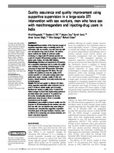
the ‘look’of the product. Features such as the size and shape of gaps and the flushness between mating components are areas that need to be controlled in order to maintain the aesthetic quality of a product. For example, Figure 1 shows two views (from the rear) of an automobile body panel containing a fuel filler flap. The fuel filler flap on the car on the left protrudes and has unacceptable aesthetic quality whilst that on the right appears to be flush with the body panel and is probably acceptable to the customer. Aesthetic quality can have a dramatic impact on the aesthetics, style and market differentiation of the final product. Because of this most automotive companies have now introduced ‘dimensional management’ processes into their overall design process. Dimensional management involves the identification, as early as possible in the design process, of the areas on an automobile where poor fits or alignments, caused by uncontrollable variations in the manufacturing processes, may cause quality problems. Ideally concept designs are altered to ensure that problems will not occur in critical areas. If it is not possible to alter the overall concept then effort is spent to ensure that the combination of the detail design and capable manufacturing processes combine to eliminate the problem. Part of the dimensional management process involves the setting of values for allowable gaps and flushes between mating panels and trims. This is not an easy process because it is difficult to know what effect on the customer perceived quality of the vehicle will be if a gap, between say, the fuel filler flap and the car body, is set at 1mm. Will it make a difference to the customer if it is set at 2mm? Whether the gap is set at 1mm or 2mm these are nominal values and will not be achieved in reality because, however good the production processes, some variation will occur in the gap width. This forces the design team to make trade-offs between the assignment of tolerances on each dimension (with a direct link to production cost) and aesthetic quality. Aesthetic quality is inherently a visual attribute and thus design teams need help in visualizing the impact tolerance assignments have on gap sizes. Design teams must also be able to visualize how the aesthetic quality changes as each component varies within its allowable tolerance (or manufacturing variation). This is because products that may be acceptable to the customer when produced from perfect components may be totally unacceptable when assembled from components towards the limit of their allowable manufacturing variation. Physical models can help the process but they are made to one size and a new model (or part of) usually needs to be created for each variation in gap size. Virtual models on the other hand can be adapted relatively easily to show different gap sizes. However virtual models must be extremely realistic because the design team must have
2
confidence that what they see on the computer screen (or other output devices) is a true representation of what the customer will see in the showroom. Thus a virtual aesthetic quality evaluation tool requires the provision of a photo realistic, interactive 3D view of the product that ‘responds’to external forces and can display geometry that varies from the perfect (or nominal) due to manufacturing and assembly variation. This paper reports the results of an experiment conducted in the context of a generalized design process followed by the design team producing body in white (BIW) designs in the BMW Group (formally Rover Group). BIW is the main, usually metallic, structural bodywork, without external and internal trims such as lights, door handles, instrument assemblies and seats. The paper outlines the mathematical models that were combined to conduct the experiment, introduces the experimental case study and summarizes initial responses from users of the system.
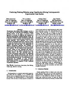
Overview of system The software architecture used in the experiment is shown in Figure 2. The software is known as VITAL (Visualization of the Impact of Tolerance Allocation). The architecture is based on a computational steering model in which the user interacts with a simulation of a model and its environment to visualize aesthetic quality under various tolerance situations. The architecture integrates several simulation models to improve the accuracy and realism of the simulated environment. The interaction model provides the interactive user interface to the system and enables the user to steer the simulation within the environment. The environment model simulates a photo-realistic environment, in which the product resides and generates a realistic lighting model for the product. The tolerance model gathers and filters the results on an off-line tolerance analysis to simulate the effects of different tolerance scenarios, such as most likely, worst-case, and best-case conditions, and enable “what-if” studies. The deformation model simulates the effects of component deformation as a result of different tolerance conditions, by deforming the geometric representation of the components. The assembly model represents and maintains assembly constraints between components and supports the interactive assembly and disassembly of the product within the environment. Finally the behavior model simulates the physical dynamics of the product within the environment, maintaining consistency against physical laws such as gravity, friction and contact dynamics.
3
Geometric and assembly variation will always occur during component manufacture and product assembly. Engineers compensate for this real world variation through the assignment of tolerances. This concept is realized within the system using a tolerance model. This model makes appropriate adjustments to a nominal product with respect to engineering knowledge of manufacturing and assembly capabilities. This enables engineers to visualize the impact of variation on the product as single instances of variation or an entire range of predicted variations. Finally, the user interacts with the all of the available models (and consequently can change or steer the simulation over time) using the interaction model. This represents the user interface to the system. The models are described in more detail in the following sections. The strategy of decomposing the system into assembly, tolerance, behavior, environment and interaction models to support aesthetic quality inspection, can be seen as a particular instance of an Immersive CAD environment as defined by the National Institute of Standards and Technology (NIST) and Washington State University [3].
Assembly Model In the early nineties research at the University of Leeds developed a novel interactive constraint-based assembly modeling system with multi-user capabilities. Unfortunately, the techniques employed for assembly did not scale well for large models of realistic complexity. More recent work at Leeds addressed these problems to produce a new interactive virtual prototyping system [5,7]. However the simulation was limited to assembly kinematics and did not address the issue of physical simulation. A number of academic institutions have also conducted research projects that combine assembly constraints with physical simulation to support assembly tasks within virtual environments [3,8,9]. In recent years, physical simulation has matured to the point where companies such as Delima (formally Deneb Robotics), Mechanical Dynamics and MathEngine have been able to develop very sophisticated and successful commercial systems that specialize in physical simulation. These systems are now integrated into most modern CAD environments and are already in regular use in many design and manufacturing organizations. The assembly model allows different levels of geometry detail to be used. As a product evolves through the design and engineering process, the corresponding CAD model becomes increasingly more detailed. Only at the
4
end of the design process might the fully detailed solid model be available. In order for the VITAL software to be useful at all stages of the design and engineering process, a virtual prototype is represented as an assembly (or group) of components. A component model is a more general representation than a solid model as it can be described geometrically as either a set of surface patches, a skin model, or as a complete solid model. The assembly structure used by the software is shown in more detail in Figure 3. Each component is composed of a material description and a geometry description. The material description is composed of physical properties and material properties. The geometry description is divided into three representations. Levels of Detail (LOD’s) consists of a number of polygon sets, each providing an approximate polygonal representation of the virtual prototype at decreasing levels of complexity. The B-REP description contains a set of surface patches (trimmed parametric surfaces) and topology information that together provide an accurate geometric description of the component. Finally, the features description represents a set of geometric shapes with specific quantifiable properties. A CAD system will usually provide most of the information required to populate the structure shown in Figure 3. Most popular CAD systems (e.g. CATIA, Unigraphics, Pro-engineer, and I-DEAS) employ Boundary Representation (B-REP) to accurately represent geometric structure using trimmed parametric surfaces with a topological structure. This data can be exported from the CAD system on a per component basis and imported into the assembly model, where it is used to populate the B-REP structure for each component of the assembly. During the import process the assembly model automatically analyses this data to generate topology (if none already exists), extracts and builds a list of geometric features. The system then uses the fast surface tessellators within OpenGL Optimizer to produce and manage polygonal representations at several levels of detail (to be switch depending of view distance). This is a common rendering optimization technique used in many visualization and CAD systems. The import process is completely automated and takes of the order of seconds on typical CAD workstations, even for relatively large complex assemblies. For example importing a new version of an entire automobile body shell assembly consisting of over 4000 individual surface patches from native CATIA model files takes approximately 90 seconds on a MIPS R10000 based SGI Octane workstation. The representation of component geometry as geometric features within the assembly model facilitates the definition of mating conditions between components. Features are extracted by analyzing the component surface
5
and topology data. Such features include basic geometric primitives, such as planar, cylindrical and spherical faces, as well as more complex geometric features, such as gears or helical surfaces (e.g. screw threads). All features have a number of basic quantifiable properties, for example dimensions, center point, normal etc. Complex features contain more specialized properties, such as pitch diameter, number of teeth and gear type for gear features. The concept of geometric features provides the foundation for creating mechanical assemblies using featurematching techniques to automatically identify valid mating conditions between compatible features [10]. Currently, the assembly model supports against (between planar features), concentric (between cylindrical features), cylindrical fit (between opposing cylindrical features), spherical (between opposing spherical features) and gear fit (between gear features). At the component level, a constraint relationship is defined by one or more mating conditions. Constraints can be created to locate components within the assembly. The interaction model uses the constraint relationships to support the interactive construction and dynamic manipulation of mechanical assemblies.
Environment Model In order to predict aesthetic quality within a virtual environment, the virtual prototype must look as realistic as possible. Thus materials, textures, shadows and even the subtle reflections of light on painted surfaces must be modeled and rendered as accurately as possible. Ray tracing packages, such as RADIANCE, Renderman™ and Alias Wavefront™ , are capable of producing extremely realistic images that are often indistinguishable from real photographs. However such packages can take hours or even days to produce such images. Recently research has attempted to bridge the gap between high-quality offline and interactive rendering using environment mapping hardware and image-based rendering techniques [11,12]. These techniques have now made it possible to render high quality photo-realistic images at frame rates suitable for virtual environments. Commercial systems, such as Opus Realizer™
from Opticore, are already beginning to exploit these techniques to provide high quality
interactive rendering of virtual prototypes for evaluating product styling options. When components are first imported into the environment model, facilities are provided for assigning basic material properties to each component, such as a base color, diffuse and specular reflection coefficients and a measure of the components’shininess and transparency. When dealing with Body-In-White (BIW) assemblies these
6
basic properties are often sufficient for initial what-if studies and aesthetic inspection tasks. Using these basic properties and a range of global and local light sources, components can be imported and visualized quickly. The environment model enables users to dynamically place and manipulate any number of directional, spot, point or strip lights into the scene and therefore to quickly mock-up a basic lighting environment. Once constructed, the lighting environment can be saved and reloaded at a later date if required. Figure 4 illustrates this using a model of the body shell assembly for the Rover R75, exported originally from CATIA. (The Rover R75 was launched to the UK market in mid-1999). In Figure 4 the environment model (i.e. product context) consists of a number of lights and a simple ground plane. It is also possible to replace the ground plane with a geometric model of a 3D scene in which the virtual prototype can be placed, such as virtual car show room. However, even with the addition of a 3D scene, the environment employs an artificial environment with artificial lighting and fails to accurately capture the semireflective painted or textured surfaces found on the final product. Therefore, the resulting visualization will always look artificial and computer generated. Although this provides an environment that engages some engineers it is not suitable for aesthetic inspection tasks where there is a need for greater realism at interactive speeds. The goal is therefore to reproduce, as accurately as possible, a real environment within which the corresponding physical product would traditionally be inspected, such as a quality audit inspection bay.
Such an environment is
represented in the environment model by means of a multi-textured cuboid with a library of radiosity maps representing the reflectance properties of different materials and paints. Using a digital camera, multiple sets of panoramic photographs are taken of a real environment. The photographs are then used to seamlessly texture the six inside faces of an appropriately scaled cuboid. From within the cuboid it is possible to reproduce any view of the photographed scene. All photographs are then merged to produce one panoramic set of high dynamic range radiance (HDRR) maps using techniques described by Debevec and Malik [12], and Cabral et al [11]. The HDRR maps are then pre-integrated against a number of Bi-directional Reflection Distribution Functions (BRDF’s), which represent the properties of each paint or material surface of the product. BRDF’s are capable of modeling the reflection from very complex surfaces, such as metallic paint or the combined effect of both an undercoat and transparent topcoat. The pre-integrated HDRR maps are then used
7
together with a ray-tracing package to generate spherical reflection maps from twenty geodesic viewpoints around the vertices of an icosahedron. Each of the steps above can be pre-computed once for each environment model and then re-used for any imported virtual prototype. Before visualizing the virtual prototype, each component needs to be assigned an appropriate material (corresponding to the BRDF’s). The entire assembly is then loaded and automatically positioned at the center of the cuboid. During an inspection task the environment model employs ClearCoat360™ from SGI to choose appropriate pre-computed reflection maps and interpolate smoothly between them and thus accurately render the reflection of light on every surface from any given viewpoint. Figure 5 illustrates the R75 Body Shell place within the context of an environment model captured from a typical inspection bay. This method was found to be more appropriate for capturing environment models based on real environments, as it more accurately captures the subtle reflection of light on painted and textured surfaces within the environment and can be used to model both indoor and outdoor lighting conditions. The main disadvantage of this method is that although the virtual prototype is free to move with respect to its assembly constraints, it must remain fixed in one location within the cuboid, i.e. the position from which the original photographs were taken. If the prototype is moved away from this point the pre-computed radiosity maps become invalid. However as aesthetic quality checks are conducted on stationary vehicles, such as an inspection cell, this method is suitable for this application and is capable of producing very accurate and realistic results at interactive frame rates.
Behavior Model The Behavior Model provides realistic simulation of the product's physical behavior. A degree of functional realism is critical because unrealistic behavior in the virtual environment undermines the engineer's confidence in the conclusions drawn from the prototype. Therefore, the behavior model is required to simulate physical characteristics such as gravity, friction, collision response, constraints and material properties. Most commercial CAD systems include very powerful tools for conducting accurate off-line simulation of rigid and flexible bodies with respect to dynamics and kinematics [13]. With such tools an engineer can specify initial conditions and observe the results, but then leave the simulation to compute the results over time. However, such tools are not sufficiently interactive when assigning aesthetic quality.
8
Known techniques that can be used for simulation are based on the theory of rigid and flexible multi-body dynamics. Newton's Laws of Motion predict the behavior of unconstrained objects. This formulation of the problem defines a set of Ordinary Differential Equations (ODE) that must be solved for each time step of the simulation. However, within the VITAL system a virtual prototype is most often defined as a constrained assembly. In addition, the problem is made more complicated by the need to respond to unpredictable user interaction and other forces resulting from collisions, friction and gravity.
Calculation of these forces is a non-trivial task.
Fortunately, a large body of techniques has been developed for multi-body dynamics and solutions to the problem have been well documented [14,15]. There are two well-known methods for defining constraints within multi-body dynamic systems. The first approach involves reducing the number of degrees of freedom (DOF) needed to describe the state of system. This reduced-coordinate formulation is more efficient for computing the state at each time step, but its efficiency is derived from a very compact formulation of the problem. Therefore, it is not flexible enough to support an environment in which users frequently change constraints in such an interactive environment.
The second
approach is Lagrange's method, which introduces additional forces to maintain the constraints. These forces are calculated via a set of Lagrange multipliers that augment the original formulation of the problem.
Such an
approach is necessary because the need to solve a set of constraint equations in tandem with the ODE means that the problem has been transformed into one involving Differential Algebraic Equations (DAEs) rather than ODEs. Since 1982 DAE systems have been the focus of considerable research activity [16]. Techniques employing Lagrange multipliers provide the current means of solving the DAEs encountered in the VITAL system. These techniques have been embodied within a number of commercial packages, in particular the MathEngine™ Dynamics Toolkit that supports real time dynamic simulation through an accessible and extensible C++ API. The behavior model has built upon this package to provide the implementation of the dynamics engine for the VITAL system.
Tolerance Model In recent years a number of software tools, such as CE/Tol 3D+ from Raytheon, VSA-3D from Variational Systems Analysis and 3-DCS from Dimensional Control Systems have become available that enable potential tolerancing problems to be identified and their impact on the total design assessed. These tools cover several aspects
9
of tolerancing within the design process and most offer Geometric Dimensioning and Tolerancing ‘Advisors’ to assist in the interpretation and understanding of dimensional data. Advisors can check and associate symbol correctness as well as identify critical measurements associated with the key product characteristics. It identifies those parts that may require additional tolerancing, have multiple tolerances that conflict with each other or are redundant. Tolerance Analysis tools allow the dimensional variation in an assembly to be predicted. The tools provide true statistical simulation modeling, with a graphic display of the variation and view of the assembly sequence defined as a tree structure and diagram or animation. Most tools can be integrated with modern CAD packages such as IDEAS and CATIA. The tools are feature based, using multiple windows and models and no knowledge of programming languages is required for operation although an open architecture allows custom routines to be coded. The tools automatically generate mathematical relationships to vary the form, orientation, location and size of geometric features. Monte Carlo simulation of a production run is executed in which feature dimensions are randomly varied based on the assigned tolerance, the allocated process capability (Cp and Cpk), and knowledge of the assembly sequence. Results can be obtained that include the standard deviation of the tolerance under investigation, percent of products that will be produced out of specification and the minimum and maximum values of the tolerance. The tools also allow "what if" scenarios to be created and analyzed. However skill is needed to interpret the output of the tolerance analysis tools and it is difficult to visualize what effect the values obtained from histograms and distribution curves have on the product’s aesthetic quality. In the VITAL software the output of a tolerance analysis package, VSA-3D, is used to determine the variation in position and size of the bounding surfaces of the virtual prototype being analyzed.
Interaction Model The interaction model represents the user interface to the VITAL system. The model controls the interaction between the physical environment (input devices such as a mouse, joystick or gloves; output devices such as monitors, HMDs or haptic devices) and the virtual environment (interaction techniques for navigation within the environment model and direct selection and manipulation of sub-assemblies, components or features within the assembly model). These interaction techniques will be described in more detail in the following sections. With
10
respect to output, the interaction model can be configured to support both mono and stereoscopic display on a wide variety of visual devices, from desktop monitors to multi-projection display systems. In particular the interaction model has been successfully tested on numerous NT and Unix-based workstations, the BMW Group Electronic Build Theatre (a dual screen stereo power wall), various Reality Centers™ and a dual-plane TAN Holobench. The interaction model currently supports two methods of navigation within the environment. With the first method the interaction model controls the actual viewing position (camera). The user simply selects an area of interest and the camera flies to a suitable vantage point. The second method allows the user to manually manipulate the camera using the traditional mechanisms of pan, rotate and zoom. These mechanisms have been found to be sufficient to enable users to quickly fly around the environment until they have located an area of interest and then manually control the viewpoint. The interaction model also supports the 3D manipulation of components within the assembly model. A user can select any unconstrained component and move or rotate it freely within the environment. If the component is constrained, its movement will be restricted so that the structural integrity of the parent assembly is maintained (i.e. a door is only able to rotate about its hinges). In addition to navigation and component manipulation, the interaction model also supports more advanced interactive assembly and disassembly tasks. Mating conditions and constraints between components can be defined interactively in one of two ways; either direct selection or direct manipulation. Direct selection requires the user to explicitly choose which geometric features to mate. After one feature has been selected, the interaction model provides some assistance by indicating features on other components that could form valid mating conditions. Figure 6 illustrates this process and the assistance offered by the interaction model at each stage of the assembly process. This method of constraint formation is most useful if the geometric features involved in the assembly process are known in advance. If the user wishes to experiment with the components to see what potential constraints can be formed or does not know how to assembly the components then an alternative method is the direct manipulation approach. With direct manipulation the user is required to select a particular component and to move it within the environment. The interaction model then predicts all possible mating conditions that exist between the selected component and all other components in the assembly model. The set of all possible mating conditions is ranked according to the Euclidean and angular proximity between the components. These are indicated to the user by highlighting the
11
mating features using an appropriate color (depending of the type of mating condition). The brightness of the color indicates the relative proximity of the feature. The interaction model automatically repositions the components to precisely satisfy any selected mating condition and a new constraint is added to the assembly model. The behavior model is responsible for maintaining each new constraint during any subsequent manipulation. For kinematic simulation this involves propagating the motion of a component to the network of components connected to it through constraints (or vice versa for reverse kinematics). Each additional constraint adds a further node to the constraint network and therefore results in an additional single matrix multiplication per frame. Thus even with complex assemblies composed of many of constraints it is possible to simulate kinematic response to user interaction in real time.
Case Study The VITAL system has been applied to the evaluation of the aesthetic quality of the fuel filler flap assembly from the Rover 75. The body in white of the Rover 75 was modeled by BMW Group using CATIA. The model used in the case study consists of the rear wing, the fuel filler pocket, a hinge bracket and pin, and the flap itself. This model represents a highly visible “A” class surface and thus any aesthetic problems, such as the gap and flush between the flap and the panel are immediately obvious. Any discontinuity in these surfaces can have a detrimental effect on a potential customer’s first impression of the overall build quality of the entire vehicle. Aesthetic problems might occur as a result of component variation and assembly misalignments during manufacture. The case study was first assembled (in a similar manner to Figure 6) to evaluate the basic open and closing functions of the flap. For this case study, variation that may hypothetically occur due to errors in assembly were introduced by applying a simple offset to the concentric mating conditions on either the upper or lower attachment points between the bracket and pocket. All parts were considered to be perfect in form and size, and thus any gap or flush conditions were a result of bracket misalignment. The assembly model automatically propagates the offset through the assembly sequence to allow visualization of its impact on the gap and flush of the flap relative to the body panel. Small changes in the flushness of the flap are difficult to see without the help of special lighting. During an automotive quality check conducted after final assembly of the automobile, a set of parallel strip lights are used to generate reflection lines along the side of the vehicle. Any problems in the flushness of the flap are then detected as
12
discontinuities in the reflection lines. It is possible to simulate these lighting conditions using an environment model within the VITAL system. Figure 7 illustrates an example of simulated strip lighting. In the figure a 1.0 mm offset has been introduced to the lower hinge attachment point resulting in an under flush condition on the lower edge of the flap and a corresponding over flush condition along the top. This can be seen as a discontinuity in reflection lines towards the bottom and top of the flap. In addition to evaluation of simulated strip lighting, the quality of the image generated by the environment model has been evaluated against photographs taken during a normal quality audit of a real vehicle randomly selected from the manufacturing line. Figure 8 gives an example of a view taken at flap height, looking square on. On the left is the original photograph, while on the right is the 3D image interactively rendered by the VITAL system. In this example the environment model is captured from an inspection bay similar to that used during the real quality audit. Using the techniques illustrated above it is possible to inspect virtual automotive assemblies to assess aesthetic quality. This allows engineers to identify an acceptable level of variation and define a quality standard early in the project. However, in order to document the quality standard, engineers need to take measurements from the assembly. The VITAL system provides methods for defining points on components in order to take measurements of values such as gap and flush. Points are defined relative to a section plane that intersects the components involved in the measurement. An example of this is illustrated in Figure 9, in which a section is defined through the leading edge of the flap (this plane is defined relative to the car line). Two points are defined to measure the gap and two to measure the flush. When the components are moved, the points will also move and the measurement automatically updated. Engineers may also enter values for gap and flush settings for a group of points, the VITAL system then moves components in the virtual environment to satisfy this new condition as accurately as possible. In this way engineers can determine acceptable visual quality standards before a physical prototype has been built. Movable geometry can be constrained by fixing selected points so that adjustment of any other points will not invalidate the gap and flush setting of the constrained points.
13
Evaluation The VITAL software was evaluated in the context of the case study described above through ‘mock’ design reviews with groups of design and quality engineers. The design reviews were supplemented by allowing selected engineers in the collaborating companies to have access to the software for use on ongoing projects. This ‘free access’ use was restricted by the non-production quality of the software. The design reviews and ‘free access’ periods were then followed by structured interviews. The evaluation criteria used were: • General system performance • Recommendations for including additional advanced functions and features • Bugs or annoyances encountered when interacting with the system • Perceived contribution to existing design processes • Advantages/disadvantages over existing practices and software • Strengths/weaknesses of the current version of the system The research has identified two distinct user groups of the software: those who will ‘drive’the VITAL system through the user interface on a frequent basis and those who attend design reviews and will use the output of the VITAL software to promote discussion and inform design decisions. The first three criteria listed above are aimed primarily at the first group of users, and the last three at the second group. The main positive outcome of the evaluation was that engineers were convinced that a commercially robust system similar to the VITAL prototype would greatly assist with the setting of quality targets. In particular, by providing visual representations of flush and gap limits, previously only listed as numbers on paper, within realistic looking environments, such a tool would help to remove some of the subjectivity associated with setting quality targets. Discussions on acceptable quality targets would take place with the design and manufacturing team and potential customers. These discussions would allow quality targets to be set earlier in the design process than currently. The engineers also suggested that an additional application for the system would be to use the interactive assembly and visualization capabilities of the VITAL software to assess component interaction within the assembly and to evaluate alternative assemblies. This would be particularly useful when testing components, such as trim design options, for alternatively priced model variants. In addition to improving the quality, lead-time and cost
14
engineers were confident that the technology would allow comparisons to be conducted earlier in the design process before physical prototypes had been produced. A common concern expressed by the engineers was the number of business processes, and software tools, that must be integrated within the concept design stage in order to make proper use of the VITAL software. Current problems associated with data exchange issues and the time taken to set up scenes (light types and positions and environment maps) combine to reduce efficiency. Unless engineers can quickly move design data into the VITAL environment, conduct ‘what if’analyses, and return the results to the design environment within a reasonable time scale, the software will not be used. The definition of the term ‘reasonable’ is still a subject of debate. Engineers would prefer that a single design iteration could be done in a matter of minutes – current data exchange and scene definition issues mean that currently this cannot be achieved in less than a day. The majority of the engineers were in agreement that the general system performance (range of functions, ease of use, visual quality) was satisfactory within the context of prototype software. Common suggestions for improvement in functionality included the incorporation of scaling overlays, dynamic sectioning, flexing simulation and clash detection. A scaling overlay is an electronic ruler that the user would apply to an inspection feature (gap, flush) to facilitate an accurate acceptability check against the upper, nominal and lower aesthetic quality standard for that feature. Dynamic sectioning would allow the user to take a dynamic section through a component or an assembly, in order to check for defects such as shape/surface inconsistencies on single or mating parts. The flexing function would provide the capability to simulate the flexing/deformation of pressed sheet metal and plastic components within the assembly process.
Conclusion The use of virtual environments to enable visualization of aesthetic quality standards early in the design process has been reported. Feedback from engineers as to the suitability of such a tool in the conceptual design process has been positive. The VITAL software has, to date, only considered assemblies that consist of rigid geometry. Automobiles contain a large number of flexible assemblies, such as interior door trims. The next stage of the research will develop more sophisticated simulation techniques to enable flexible assemblies to be considered.
15
The research has only considered the problem of aesthetic fits and alignments. It is recognized that although an extremely important area for the automotive industry, it is only a subset of the tolerance analyses that are required. The output of the research has given the design engineers at the collaborating companies confidence that virtual environments can have a significant positive impact on design and manufacturing business processes.
Acknowledgments The authors wish to acknowledge the contributions of design and project engineers at the collaborating companies. The advice of Bill Singh Nigel Faulkner and Alan Olifent (BMW Group) and the provision of CAD data from BMW Group are particularly appreciated. Steve Watson at SGI contributed to the solution of data exchange issues and provided advice on developments in visualization technology. The research has been conducted with the support of Grants GR/M17099 and GR/M12094 from the UK Engineering and Physical Sciences Research Council. The project is supported by Magna Interia Systems and SGi. A VITAL Web site exists at http://www.vsp.co.uk/tenants/vital/. An earlier version of this paper was published as paper number DETC2000/CIE-14591in the 2000 ASME Computers and Information in Engineering Conference, Baltimore, Maryland
References 1. Baylis G. M., Bowyer A, Taylor R. I., and Willis P. J., Virtual Manufacturing, Proceedings of CSG ’94, Winchester, UK, April 1994, Session: Set-theoretic Solid Modeling: Techniques and Applications, pages 353365. 2. Beier, K. P., Virtual Reality in Automotive Design and Manufacturing, in Proceedings of Convergence ’94, International Congress on Transportation Electronics, SAE (Society of Automotive Engineers), Dearborn, Michigan, October 1994. 3. Jayaram S., Wang Y., Jayaram U., Lyons K., and Hart P., A Virtual Assembly Design Environment. In Proceedings of IEEE Virtual Reality 99, Houston, Texas, USA, March, 1999. 4. Srinivasan H., Figueroa R. and Gadh R., Selective Disassembly for Virtual Prototyping as Applied to DeManufacturing, in Journal of Robotics and Computer Integrated Manufacturing, Vol. 15, No.3, pp. 231-245, 1999. 5. Thompson M., Maxfield J. and Dew P.M. Interactive Virtual Prototyping. In Proceedings of Eurographics UK ‘98, pages 107-120, March 1998. 6. Wilson J. R., Brown D. J., Cobb S. V., D’Cruz M. M., and Eastgate R. M., Manufacturing Operations in Virtual Environments (MOVE), Presence, Vol 4, No. 3, Summer 1995, pages 306-317. 7. Maxfield J., Fernando T., Dew P.M.. A Distributed Virtual Environment for Collaborative Engineering, Presence, The International IEEE Journal of Teleoperators and Virtual Environments, volume 7, number 3, 1998.
16
8. Blinn J. F., and Newell M. E., Texture and reflection in computer generated images, in Communications of the ACM, 19 (1976), 542-546. 9. Kuehne R. and Oliver J., A Virtual Environment for Interactive Assembly Planning and Evaluation, in Proceedings of Workshop on Simulation and Interaction in Virtual Environments (SIVE ’95), The University of Iowa, July 13-15, 1995. 10. Baxter J. E., Juster N. P., and de Pennington A., An Assessment of Assembly Mating Conditions in the Context of a Product Model, ASME Computers in Engineering, volume1, 1992, pages 421-428. 11. Cabral B., Olano M., Nemec P. Reflection space image based rendering. SIGGRAPH 99 Conference Proceedings (Aug.1999), Annual Conference Series, ACM SIGGRAPH, Addison Wesley. 12. Debevec P. E. and Malik J. Recovering high dynamic range radiance maps from photographs. SIGGRAPH 97 Conference Proceedings (Aug.1997), Annual Conference Series, ACM SIGGRAPH, Addison Wesley, pp 369378. ISBN 0-89791-896-7. 13. Gillespie and J.E. Colgate. A survey of multibody dynamics for virtual environments, Proceedings of the ASME International Mechanical Engineering Congress and Exhibition, 1997. 14. Baraff, D, Dynamics Simulation of Non-Penetrating Rigid Bodies. PHD thesis, Department of Computer Science, Cornell University, Ithaca, NY, March, 1992. 15. Pinson S. Goyal and F.W. Sinden. Simulation of dynamics of interacting rigid bodies including friction I: General problem and contact model. Engineering with computers, 10:162-174, 1994. 16. Petzold. Differential algebraic equations are not ode’s, SIAM J. Sci., Stat. Compu., 3(3): 367-384 1982.
17
List of Figures
Figure 1: Views of two cars of the same model Figure 2: VITAL Software Architecture Figure 3: Assembly and Component Structure Figure 4: Defining Environment Lights Sources for the Rover R75 body shell assembly Figure 5: A R75 body shell assembly placed within the context of a real inspection bay Figure 6: Fixing a hinge bracket to a pocket with a combination of against and cylindrical fit mating conditions using the direct selection technique
Figure 7: Simulated Strip Lighting on the R75 Fuel Filler Flap Assembly Figure 8: Image accuracy comparison between the real product (left) and virtual prototype (right) Figure 9: Taking measurements from an assembly during aesthetic inspection
18
Figure 1: Views of two cars of the same model
19
Interaction Model (User Interface)
VITAL Environment Model Tools Feedback to the user Third Party Tools
ClearCoat ™ Rendering
Tolerance Model
Deformation Model
Assembly Model
Behaviour Model
PQP Collision Detection & MathEngine Dynamics OpenGL Optimizer Visualise Results
Figure 2: VITAL Software Architecture
20
Assembly
Component
Material
Physical Properties
Lighting Properties
Geometry
LOD's
B-REP
Polygon Sets
Surface Patches
Figure 3: Assembly and Component Structure
21
Features
Topology
Figure 4: Defining Environment Lights Sources for the Rover R75 body shell assembly
22
Figure 5: A R75 body shell assembly placed within the context of a real inspection bay
23
Step 1: Put bracket against mount plate
Step 2: Align top attachment point using a concentric fit
Step 3: Align bottom attachment point using a concentric fit
Figure 6: Fixing a hinge bracket to a pocket with a combination of against and cylindrical fit mating conditions using the Direct Selection technique
24
Figure 7: Simulated Strip Lighting on the R75 Fuel Filler Flap Assembly.
25
Figure 8: Image accuracy comparison between the real product (left) and virtual prototype (right)
26
Figure 9: Taking measurements from an assembly during aesthetic inspection
27