2013 IEEE 1st International Conference on Condition Assessment Techniques in Electrical Systems
Prediction of Transformer Winding Displacement from Frequency Response Characteristics M. Arul Sathya, Ajith John Thomas, S. Usa Division of High Voltage Engineering, College of Engineering Guindy, Anna University, Chennai- 600 025, Tamil Nadu, India
[email protected]
Abstract-The failures caused by short circuits are one of the causes of transformer outages. The short circuit currents induce excessive forces in the transformer windings which result in winding deformations affecting the mechanical and electrical characteristics of the winding. In the present work, a 722VA transformer winding is considered for the short circuit force and displacement analyses. The winding is subjected to short circuit current and the respective displacement of the winding is simulated and compared with the measurement. By using Finite element analysis, change in equivalent circuit parameters due to displacement is calculated and corresponding change in sweep frequency response is measured using SFRA. An attempt has been made to predict the displacement profile from change in resonant frequency in case of displaced conditions. Keywords—winding displacement, finite element method, short circuit forces, transformer, transient structural analysis
I.
INTRODUCTION
Power transformer is one of the major and key apparatus in electric power system. Monitoring and diagnosis of transformer fault is necessary for improving the life period of transformer. The failures caused by short circuits are one of the causes of transformer outages. The short circuit currents induce excessive forces in the transformer windings which result in winding deformations affecting the mechanical and electrical characteristics of the winding[1]. Depending on the distribution of forces and mechanical strength of the windings, the winding undergoes deformation. If these forces are not properly restrained, a major failure is likely to occur. Sweep Frequency Response Analysis(SFRA) is used to detect mechanical failure or movement of windings due to short circuits, mechanical stresses or transportation. This is an offline test and unique method to detect winding deformations (FRAX user’s manual, 2009). In reference[2], axial and radial winding deformation is developed and analyzed using sweep frequency response analysis for the manually displaced windings. S.C. Xi [3], has reported on core and winding vibration using wavelet package. J.R.Secue and E.Mombello [4] present a survey on the alternatives in the measurement techniques and interpretation of SFRA measurements. K. Ludwikowski and K. Siodla [5] investigated on frequency ranges which can be treated as diagnostic bands for detection of the winding deformation, specifically of a buckling phenomena in a high power transformer. In [6], responses with the large variations the measured frequency range are obtained
978-1-4799-0083-1/13/$31.00 ©2013 IEEE
as a result of change in the impedance of the complex L-C-R distributions of the windings. In this present work, the deformation profile of the winding for different short circuit currents are computed using magneto structural analysis and compared with the measured values. The change in winding capacitance and inductance due to deformation are calculated using FEM and the corresponding shift in resonance frequencies are obtained using circuit simulation packages. Using the above approach, the maximum displacement can be predicted from which the mechanical withstand capability of the winding for different short circuit currents can be predicted. II.
WINDING UNDER STUDY
A 722VA, 10V winding with rectangular aluminum conductor with paper insulation used by Gopalakrishna [7] is considered for the analysis. The transformer has two identical windings with 2 discs per winding. Each disc has 10 turns as shown in Fig. 1(a). The windings are connected in such a way to simulate a transformer with the winding currents in the opposite directions as shown in Fig. 1(b). The spacers used in the winding are similar to real transformer spacer as shown in Fig. 1(a).
(a)
(b)
Fig. 1. (a). Windings (b)Winding connection
III.
TRANSIENT STRUCTURAL ANALYSIS
As the short circuit current varies with time, the induced force also varies with time resulting in continuous movement of discs. Hence, it is essential to estimate the displacements using structural transient analysis and the same can be carried
CATCON2013
2013 IEEE 1st International Conference on Condition Assessment Techniques in Electrical Systems out using winding equivalent structural model [8]. To do the structural transient analysis, each disc is assumed as a lumped mass and spacer and the insulation between the discs are represented as a spring and dashpot respectively and is shown in Fig. 2.
In general, as the energizing current is
I (t ) = I max sin(ωt )
The corresponding force is given by,
⎡1 − cos(2ωt ) ⎤ F a (t ) = Fmax ⎢ ⎥ 2 ⎣ ⎦
F (t) C5
K5
(2)
(3)
M4 K4
where Fmax is obtained from magnetic analysis and Fa (t) is given as an input to the transient structural analysis.
C4 M3 C3
K3 M2
C2
K2 M1 K1
C1
Fig. 2. Equivalent structural model of the windings
z r
The governing equation for structural transient analysis is given as,
{
}
Fig. 3. Magnetic Flux distribution of the winding
(1)
70
D Length of Line CD in mm
2 [M ] ∂ {u} + [C ] ∂ {u} + [K ]{u} = F a (t ) ∂t ∂t
where: [M] = structural mass matrix [C] = structural damping matrix [K] = structural stiffness matrix {u} = nodal displacement vector {Fa (t)} = applied load vector
60 50 40 30 20 10
z -r
0 -1.5 -1 -0.5
0
0.5
1 1.5
To carry out the analysis, the following parameters are required, A. Short circuit force vector Fa (t) along the entire winding B. Structural parameters of the winding, like mass (M), stiffness (K) and damping coefficient (C) of the winding.
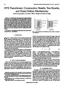
Fig. 4. (a). Distribution of axial force ( maximum) (b). Variation of axial force along line CD
A. Short Circuit Force Fa (t) using FEM
B. Measurement of Structural Parameters
The electromagnetic force distribution in the windings is computed using FEM Workbench. Both the windings are energised with same current of density 12 A/mm2 in the opposite directions.
Modal testing is a form of vibration test on an object by which natural frequencies, stiffness, masses and damping ratios can be determined. This test is carried out in Council of Scientific & Industrial Research (CSIR), Government of India, Chennai.
The magnetic field analysis on the windings is carried out for short circuit current density of 12 A/mm2. Fig. 3 shows the flux plot of the winding. From the magnetic flux plot, it is observed that the axial flux is negligible (as the axial flux produced by windings A and B get cancelled) compared to the radial flux. As a result, the force on the windings are only in axial directions and repulsive. Fig. 4(b) and 4(c) show the axial force distribution of the transformer for the peak current density.
C
Force in kN/mm3
(a)
(b)
The measurement is carried out using an accelerometer fixed at a point on top of the test object. The test object is excited using a hammer impact. The natural frequency of the test object is found to be 21.52 Hz and the stiffness of the total system is calculated as 282.47×10³ N/m with mass (M) of 15 kg. From the rate of decay of free oscillations of the test object, the damping constant of the total system is calculated as 811.5.
304
CATCON2013
2013 IEEE 1st International Conference C on Condition Assessment Techniques in Ellectrical Systems C. Displacement due to Short Circuit Forcess mputed using load The displacements in windings are com transfer (from electromagnetic to structural analysis) method using FEM-Workbench. The force on eaach disc ( Fa (t)) calculated from magnetic analysis act as load l for each and every node in transient structural analysis as a given in Fig. 2 and Equation (1). The displacements of all discs d are computed and Fig. 5 shows displacement of the top discc.
( (a)
Displacement in mm
3.0 2.5 2.0 1.5 1.0 0.5
( (b)
0
0
0.05
0.10
0.1 0.20 Time in seconds
0.25
0.30
Fig. 5. Displacement of top discc
IV.
MEASUREMENT OF WINDING DISPLACEMENT D
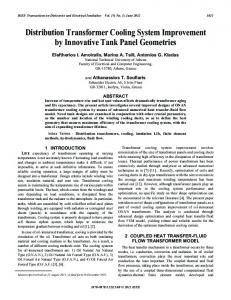
To validate the simulated results, shorrt circuit test as per IEC Standard [9] is conducted on the test object o at On Load Gears, Ambattur, Chennai. Fig. 6(a) shhows the healthy condition of the winding before short circcuit test. Fig. 6(b) shows the displacements of all the discs during d short circuit test.
(a)
Fig. 7. (a). Excitation current (Meeasured) (b) Displacement waveform (Measured)
It is observed from Fig. 5 and Fig. 7(b), the disc movement pattern is similar and a the percentage error in the maximum displacement is 4% for the same current density. As the simulation methodology is i validated using experimental results, further analysis is carrried out for different currents using simulation. V.
W DISPLACEMENT PREDICTION OF WINDING PRO OFILE
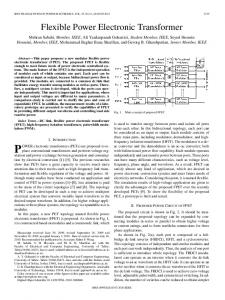
The above described methodology is carried for predicting the displacement proofile (displacement of all discs) for different short circuit currennts and shown in Fig.8.
(b)
Fig. 6. (a)Winding before test (b)Winding after test
A linear displacement transducer witth 1.5 mm linear stroke length is used for measurement. Using the transducer the displacement of the top disc due to repulssive force between A and B is recorded and shown in Fig.77. The maximum displacement of the top disc is found to be 3..02mm at 0.11 s.
Fig. 8. Current dennsity Vs Displacement
305
CATCON2013
2013 IEEE 1st International Conference C on Condition Assessment Techniques in Ellectrical Systems VI.
CHANGE IN RESONANCE FRE EQUENCIES
The change in the axial distance bettween discs due to different magnitude of short circuit currents,, results in change in the inter disc circuit parameters. Thhe total winding capacitance ( disc , inter disc and ground caapacitance) and the inductance ( self and mutual inductance) arre calculated using FEM and compared with analytical values obtained o as in [10] and [11]. The percentage change in total capacitance and inductance of the winding (top and bottom) for different short circuit currents with reference to the norm mal winding are tabulated in Table 1 and 2. TABLE I.
( (a)
CHANGE IN TOP WINDING CAP PACITANCE AND INDUCTANCE Top Windingg Capacitance
Current density (A/m2)
Total in (pF)
% change
Inductance Total L in (uH H)
% change
( (b) Fig. 9. (a) Change in resonant frequency for Top Disc (b) Change in resonant frequency for Bottom Disc
Without Deformation
14.424
12e6 14e6 16e6 18e6 20e6
14.022 13.920 13.830 13.680 13.522
1005 2.7 3.5 4.1 5.2 6.2
1044.2 103.95 103.96 103.57 103.16
.076 1 0.99 1.36 1.75
For different short circuitt currents, the percentage change in first resonant frequency for top and bottom disc is given in Table 3 and Table 4 respectivelly. TABLE III.
% CHANGE IN RE ESONANT FREQUENCY FOR TOP DIISC
Short circuit current in A/m2 TABLE II.
CHANGE IN BOTTOM WINDING CAPACITANCE C AND INDUCTANCE
Healthy 12e6 14e6 16e6 18e6 20e6
Bottom Winding Current density (A/m2)
Capacitance Total C in (pF)
% change
Inductance Totall L in (uH H)
Reesonant freq quency in MHz 4.08 4.17 4.179 4.18 4.27 4.28
% Change in resonant frequency -2.2 -2.43 -2.45 -4.66 -4.9
% change
TABLE IV.
% CHANGE IN N RESONANT FREQUENCY FOR BOTTO OM DISC
Without Deformation
14.53
12e6
15.31
-5.40
888.5
-1.14
Short circuit current in A/m2
14e6
15.58
-7.22
88.8839
-1.5
16e6 18e6 20e6
15.63 15.84 16.10
-7.57 -9.00 -10.80
88..86 89..09 89..34
-1.56 -1.8 -2.1
877.5
The change in resonance frequenciees due to various displacements for different currents is compputed using Circuit Simulation Package (OrCAD PSpice). The excitation signals are given as inpput to Disc A and Disc B separately for both normal and short circuit conditions. The simulation results as shown in Fig. 9(a)) and 9(b) for both top and bottom disc respectively.
Healthy
R Resonant freq quency in MHz 4.477
% Change in resonant frequency -
12e6 14e6 16e6 18e6 20e6
4.267 4.26 4.21 4.2 4 4.1786
4.7 4.8 5.9 6.2 6.67
From the change in first f resonance frequency, the displacement profile can be predicted from Fig 8. The above analysis can also be used to preedict the withstand capability of transformer by calculating thee winding impedance from the deformed winding dimensions at the design stage itself as per IEC Standard [9].
306
CATCON2013
2013 IEEE 1st International Conference on Condition Assessment Techniques in Electrical Systems VII. CONCLUSION In the present work, the deformation profile of the winding for different short circuit currents are computed and compared with the measured values. The change in winding capacitance and inductance due to deformation are calculated using FEM and the corresponding shift in resonance frequencies are obtained using circuit simulation packages. Using the above approach, a detailed methodology for predicting the deformation profile of transformer windings under short circuit conditions is explored from the change in resonant frequency of the deformed winding at the design stage itself. ACKNOWLEDGMENT The authors are thankful to Mr. B. Babu, ExecutiveTesting, On Load Gears, Circuit Breaker Manufacturer, Ambattur, Chennai and Dr. N. Gopalakrishnan, Senior Principal Scientist, Advanced Seismic Testing and Research Laboratory, CSIR Campus, Taramani, Chennai for their support in carrying out the experiments successfully. The authors are also thankful to late Dr. V. Jayashankar for the transformer winding and his useful suggestions. REFERENCES [1] Waters, M., “The Short-Circuit Strength of Power Transformers”, McDonald & Co. Ltd, London, 1966.
[2] A.P.Purnomadi, D.Fransisco, “ Modeling and Diagnostic Transformer Condition Using Sweep Frequency Response Analysis”, Proceedings of the 9th International Conference on Properties and Application of Dielectric Materials, July 19-23, 2009, Harbin, China. [3] S.C.Xi, “The application of vibration method in monitoring the condition of transformer winding”, High Voltage Engineering, Vol. 28, pp. 12-14, Apr. 2002. [4] J.R.Secue, E.Mombello, “ Sweep frequency response analysis (SFRA) for the assessment of winding displacements and deformation in power transformers”, Electric Power Systems Research 78 (2008). [5] K. Ludwikowski, K. Siodla and W.Ziomek, “ Investigation of Transformer Model Winding Deformation Using Sweep Frequency Response Analysis”, IEEE Transactions on Dielectrics and Electrical Insulation Vol. 19, No.6, December 2012. [6] G.M. Kennedy, A.J. McGrail and J.A.Lapworth, Doble Engineering, “ Transformer sweep frequency response analysis [SFRA] ”, Energize-October 2007-Pages 28-33. [7] Gopalakrishna. S, ”Detection of Winding Deformation in Transformers during Short Circuit Tests”, Ph.D. dissertation, Indian Institute of Technology Madras, 2010. [8] Hongkui Li, Yan Li, “Axial vibrations modal analysis and computation of Power Transformer Windings under different levels of Pre-Compression”, IEEE International Conference on Applied Superconductivity and Electromagnetic Devices, Chengdu, China, September 25-27, 2009. [9] International Standard for Power Transformers – Part 5: Ability to withstand short circuit, IEC 60076-5. [10] Karsai, K., Kerenyi, D. and Kiss, “Large power transformer”, Elsevier, Amsterdam,1987. [11] Frederick W. Grover, “ Inductance Calculations Working Formulas and Tables”, D. Van Nostrand Company Inc. 1946.
307
CATCON2013