Part winding resonance: Demerit of interleaved high-voltage transformer winding A.De and N.Chatterjee
Abstract: Interleaved transformer winding is a new and promising development in the field of design of high-voltage transformer windings. Although the strengths and weaknesses of the interleaved winding concept against surge voltages are theoretically known, implementation in a practical multiwinding EHV transformer may lead to various complications and the winding can show unpredictable behaviour contrary to existing knowledge. A comparative assessment of interleaved transformer winding has been made by EMTP simulation of two identical multiwinding EHV transformer models having interleaved and noninterleaved conventional disc windings. The observations regarding relative surge performance of interleaved and noninterleaved windings may throw some light on optimum interleaving of the disc coils in transformer winding. The tap changer or regulating winding forms a weak point in H V transformers and is found to be responsible for the majority of failures. Distribution of impulse voltage in the regulating or tap-changer winding has also been studied. The results of these observations may be useful in finding suitable explanations for the failure of tap-changer windings in EHV power transformers
1
Introduction
The distribution of impulse voltage in transformer winding has long been a factor of significant importance in the design of high-voltage transformers. With the very large EHV power transformers now being built, an accurate assessment of the voltage stresses likely to occur under surge conditions is essential to achieve an optimum insulation design. The behaviour of a surge-stressed transformer winding is studied using analogue models or by numerical methods using a digital computer. The analogue model is an impor-
of other windings to ground, e.g. solid grounding or grounding through resistance, and the degree of nonhomogeneity in the windings caused by local reinforcement of the turn insulations, etc. An accurate mathematical analysis that would cover all these aspects is virtually impossible. In the present paper, an alternative solution to the problem has been approached which involves the development of a suitable model for the concerned transformer winding with concentrated inductances, capacitances and resistances that only simulate the electrical quantities without any geometrical resemblance [3] and finding a suitable numerical method of analysis utilising circuit solution principles [4].
tant tool, since the response of a well-constructed model is
The present work deals with the response under lightning
in reasonably good agreement with that of the original [l]. However, the analogue model method has certain limitations. First, it is costly and time consuming. Secondly, it lacks the flexibility, as trying several alternative designs usually requires building of several models. On the other hand, applications of mathematical analyses for determination of transient processes in transformer windings is mostly confined to single-layer cylindrical coils and rectangular incident waves [2]. However, transformers, especially the high-voltage high power types, are much more intricate systems than the single-layer coil system. Such systems are too complicated to permit mathematical analysis without simplifying assumptions. Transient response depends on several factors, such as the type of winding under consideration, the manner in which the winding is subjected to surge, the manner in which other windings are connected, the type of connection
impulse of a three-phase, 31.5MVA, 132kVi33kV star/delta transformer with tap-changer winding, having interleaved continuous disc winding throughout. To study the effect of interleaving of turns of the high-voltage windings, transient studies have been made on another identical transformer, having noninterleaved conventional disc winding, for a comparative assessment. Equivalent high-frequency circuit models of the transformer windings concerned have been developed taking into consideration various electrostatic and electromagnetic interactions [5]. The method described requires the transformer winding to be replaced by a more or less complicated ladder network with finite or infinite number of elements depending on whether its parameters are considered lumped or distributed. However, reduction of the continuously distributed self and mutual inductances from the original winding to corresponding lumped parameters in the equivalent circuit is dificult and requires extensive mathematical formulation.
0IEE, 2000
2 Equivalent circuit representationof transformer winding
IEE Proceedings online no. 2oooO304 DO1 IO. 1049/igepa:20000304 Paper fmt received 30th June 1999 and in revised form 21st Januaty 2000 The authors are m i t h the EleCtrical Engineering Department, Jadavpur University, Calcutta 700 032, Indirt IEE Pruc.-Elrctr. Power Appl., Vol. 117, No. 3, M u y 2000
The accuracy of the results obtained from the equivalent circuit method depends entirely on the degree of sophistication introduced in the representation of the windings. The 161
equivalent circuit must describe the surge behaviour of the windings for wide range of variation of the input pulse voltage wave shape and must be responsive to hgher frequencies [6]. At the same time, the amount of computational time and cost involved in the solution of such models should also be taken into consideration [7]. The most detailed modelling will be one in which every turn of the winding is represented and all the turn-to-turn inductances and capacitances are considered. This type of representation is capable of describing the transient behaviour of each winding turn in detail [SI. However, such a model may be prohibitive from the consideration of computer memory requirement, CPU usage and running cost. Various degrees of simplifications are possible until the network is reduced by successive lumping of the elements, to a simple RLC circuit of a few elements [9]. Most of the practical transient studies are based on coil-by-coil representation of the winding. By such representation, the identity of the individual turns is no doubt lost but the sections can still be identified. This form of winding representation provides sufficient detail of the surge behaviour of the winding in the normally encountered frequency range of 20 200kHz. Values of the lumped parameters used in the equivalent circuit are calculated from the dimensions and physical properties of the transformer material and are greatly dependent on the coil and terminal connections of the transformer.
-
3 Development of equivalent circuit of transformer windings
have been lumped together to form single equivalent mutual inductance [15]. The effect of an iron core of the transformer has not been considered in the computation of inductances [I].
3.4 Equivalent series resistance Effective resistance of the coils has been considered, taking into account nonuniform distribution of current in thc conductors due to skin effect and eddy currents (Section 7.4). However, parallel resistances, representing dissipation losses in the capacitor dielectrics, and eddy current losses in the conducting cylinder formed by low-voltage winding have been neglected.
3.5 Shunt capacitances between different winding sections Shunt capacitances between main and tap windings have been considered to take into account electrostatic coupling between the windings.
3.6 Mutual inductance between distinct winding sections Mutual inductances between main and tap windings has also been considered to take into account inductive coupling between the windings. All the inductance components have finally been lumped together to an easily representable form of ‘equivalent inductance per disc coil’ (Section 7.2.2), using the method suggested by K.A. Wirgau [ 151. 4
The equivalent circuit is developed utilising the winding parameters of a 31.5MVA 132kVl33kV transformer, impulse tested at the High Voltage Laboratory using the neutral current method with the winding terminals connected as per IEC specification [5]. The present equivalent circuit model contains 78 elementary sections, representing 46 main and 32 tap winding discs. A schematic diagram of the equivalent circuit model has been presented in the Appendix (Section 7.6). In the equivalent circuit developed, the following basic R,L, C parameters have been considered:
3. I
Series capacitance of each coil
In the calculation of series capacitance (Section 7.3), interturn as well as interdisc capacitances between adjacent coils have been taken into consideration [lo, 111. Small stray capacitances between one coil to other distant coils have been neglected.
3.2 Shunt capacitance between coils and neighbouring earthed bodies The earthed bodies include both the metal tank as well as nonimpulsed windings, which have also been earthed either directly or indirectly through resistance at the time of impulse testing.
3.3 Self and mutual inductance Self inductance of the disc coils has been calculated (Section 7.1), using Grover’s extension to Rosa’s formula for computation of self inductance of circular disc coils of rectangular cross-section [121. Mutual inductance between the disc coils have been calculated (Section 7.2), by the Lyle method of equivalent filament [13], and the tables presented by Grover [14]. Since, in a lumped parameter transformer model, representation of evenly distributed numerous mutual inductances formed by each coil with the other coils is virtually impossible, the distributed mutual inductances 168
Discussion of results
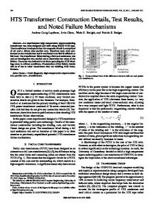
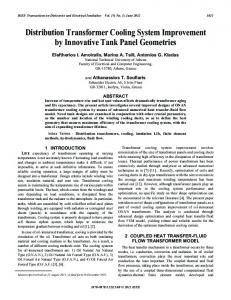
Results obtained from EMTP simulation of the transformer models are presented here. In Figs. 1-5, VHMI.,,, and VH,,-,,, correspond to voltage with respect to ground at the ith disc of HV main winding, andjth disc of HV tap winding, respectively, and ‘disc HMI-HM,,1’ corresponds to the ith disc of high-voltage main and ‘disc H7;-HTJ+1’ corresponds to the jth disc of high-voltage tap winding (Fig. 12). The peak of the incident impulse voltage was chosen to be 550kV as per the test specification [5] for a 132kV transformer. In all the stages of investigation the transformers were assumed to be operated under nominal tapping condition. Therefore the interconnecting lead of the 16th and 17th tap winding discs, i.e. the point HT17 in the equivalent circuit model of Fig. 12 has been grounded. It is obvious that accuracy and reliability of the results obtained from the equivalent circuit model depends entirely on validity of the modelling technique, as well as on how realistic the mathematical formulations are. Reliability of the computational results can be ensured by comparing the results obtained from the model to the actual test results of the transformer concerned. In the present case, comparison is made of the neutral current obtained during actual impulse testing and that obtained from the model. The structure of the neutral current depends on the circuit parameters of the transformer under test. Any change in the magnitude of the circuit parameters like inductance and capacitance is reflected on the neutral-current oscillogram and is universally considered a reliable checking method. The neutral current obtained from the proposed model under identical circuit conditions and voltage has been presented (Section 7.5, Fig. 116) for comparison with the actual neutral-current oscillogram obtained during impulse testing (Fig. llu) in support of the capability of the proposed model to reproduce true behaviour of the winding. From Figs. la and 6, illustrating time dependence of potential at different points of the HV main and tap windIEE Proc -Elect, Power Appl
Vol 147 No 3, Muy 2000
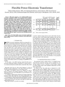
ings for interleaved winding design, it is observed that the potentials from various points to ground are almost linearly distributed over the length of the windings from line end to ground. This signifies the improvement in the surge performance of the windings due to interleaving of the turns when compared with the results for noninterleaved winding as illustrated in Figs. 2a and b. This is also evident from the spatial distribution of potential. The spatial potential distribution curves for noninterleaved design shows a highly nonlinear initial distribution (Fig. 3b), as the line-end portion of the main winding is severely stressed compared with other parts of the winding. Up to a time of 2 ~ ( sfollowing application of the voltage, the initial 50% of the winding from the line terminal withstands 100% of the applied potential. Mid-winding portions are stressed at a delayed time as the applied surge travels through the length of the winding with finite velocity. From Fig. 3b it is observed that the peak of the voltage wave reaches as high as 420kV at a point approximately 20 discs away from the . a further delayed time of 50w, line terminal after 3 0 ~At voltage peak occurs at the 32nd disc from the line terminal with a lesser magnitude of 380kV. This indicates attenuation of the wave peak owing to various losses as the wave gradually propagates through the winding. Comparative figures for the interleaved design show a perfectly linear spatial distribution till 3Ops following application of the voltage (Fig. 3u) after which the distribution tends to be nonlinear, although the degree of nonlinearity is much less compared with the case of noninterleaved winding.
600r
-2001
I
a 150r
100
> Y
50
W
-8
0
c
0 >
- 50
-
1 50
0
5
0
100
150 time, v s b
200
1 250
- H M I - G N D a- HM20-GND -....- HM HM5-GND - - HM40-GND IO - GND
600r
Fig. 2
b H T I - G N D HT25-GND HTB-GND HT33-GND HTl7-GND Tine dependence ofpotential to groundfrom
[email protected] of ~ f m i -
mg for noninterleaved design a HV main winding b Tap winding
> Y (5, W
-
1
0
> Y 0)
0 m
-1001
I
I
I
6
-
c
0
a
100r
80
60
> Y
(5, 0)
a
I \
600
LO
5 0 0 k
20
0
c
0
>
-20
Y
0)
-LO
0 0 d c
- 60
> 0
-801 0
100 150 time,vs b
50
o
M I - GND - - HHM5-GND .... HMIO-GND -
-Fig. I
1
I
HM20 -GND HM40 -GND
200
250
b H T l - GND HT8 - GND HT17 -GND HT25 - GND HT33 - GND
Tune ~ ( eendence ofpotentud to groundfionz d@ermfpomts of wind-
ing for mterleuvedDdeJzgn a HV main winding b Tap wnding
IEE Proc.-Electr. Power Appl., Vol. 147, No. 3, May 2000
-2001
I
I
H M I HMI1 HM21 HM31 HMLl HT5 HT15 HT25 disc n u m b e r b -0.5us ----Ius .....2)Ls - 1ous - - - 3oUs 50ws xxxx 1 0 0 ~ s Fig.3 Spatial distribution potential along length of winding3 a For interleaved design b For noninterleaved design 169
The improvement in linearity of the potential distribution curves for the interleaved design is caused by the large increase of series capacitance of the winding discs owing to interleaving, while shunt capacitance values remain practically unaltered for both designs. Waveforms of the disc voltages for interleaved and noninterleaved designs are presented in Figs. 4 and 5. respectively. For either design, the line end discs are observed to be highly stressed. However, the severity of voltage stresses is greatly reduced in the case of interleaved design. The peak value of potential across the first line-end disc is found to be as high as 88kV for the noninterleaved design (Fig. 5a), which is about 16'Yn of the applied impulse peak and eight times the expected peak value assunling ideal uniform distribution. The corresponding peak value for the interleaved design is 22.5kV (Fig. 4u), about twice the average value expected from an ideal uniform distribution. The 5th and 15th discs are observed to be stressed at voltage peaks of 44 and 30kV for noninterleaved design. These stresses are reduced to 19.5 and 13kV, respectively, by interleaving winding sections. Further reduction of stresses on the line-end disc is possible if instead of two-section interleave grouping, four or more sections are grouped together, thereby further increasing the self capacitance of line-end discs. Other known methods of stress control like use of line-end shields is also possible. 1
25 r
1
1
100
60
-401
a
10 7
5
1 W
B
o
c d
> 0
-5 -101 5
1
-
0
20\ 15
50
---
....
--
-_
200
100 150 time,ps b
b
a
H M I - HM2 HM 5 - HM6 HM15-HM16 HM25 - HM26 HM35-HM36 HML5 -HM46
250
-
H T l HT2 HT5 - H T 6 HT16 - HT17 HT20 - HT21 HT25-HT26 HT32 -HT33
or leuwd &sign Fig. 5 7 " e cieyauimce of d ~ ~ p t e n i l a l s fironwitet F ~nidm I winding discs h Foi tap windiiig discs
U
6 >
Y
4
w - 2 0,
s o >
-2
-4
"
1
200
250
b
a b HMI - HM2 HTI -HT2 c HM5 - HM6 HT5 - HT6 .... HM15-HMI6 HT16-HT17 - HM25 -HM26 HT20-HT21 - - HM35 -HM36 HT25 -HT26 HM45 -HML6 HT32 -HT33 ? ' h e &wrr&iice of ciix poiennticdsj&~in~er/euved ciesigtz
-
Fig. 4
v
W
V
-6v - 8L d . L 0 50 100 150 time,ps
For niaili winding disc5 h For tap winding discs
U
These observations are well in agreement with the theory, as well as with the well-known expenniental observations pertaining to studies on analogwe models of winding by different researchers [I, 151. 170
For either design, the potential across tap-winding discs exhibit sustained oscillatory behaviour (Figs. 4b and 5b). For interleaved design, these oscillatory voltages are highly underdainped and practically unattenuated, giving indication of part winding resonance in the tap winding. Chance of occurrence of part winding resonance is higher in the case of interleaved winding design, as an interleaved winding has a lower resonant frequency, owing to its high series capacitance, so that input excitation even in the form of a standard lightning llnpulse can force the winding to oscillate in its natural frequency. This is of serious concern to the design engineer. To avoid such unwanted resonance in any part of the high-voltage windings. the resonant frequency of the winding sections should always be predetermined. If possible, the response of the model winding to different possible f o r m of input excitation should be studied before implementation so that the designed winding can successfully withstand even nonstandard voltage waveshapes having a high-frequency spectrum component of large amplitude in operation. In the present case, interleaving of tap-winding discs has reduced the estimated resonant frequency of the tap-winding discs from a value of 80kHz for the noninterleaved design to as low as 22kHz in the case of the interleaved deign. Since the new value is quite close to the input excitation frequency of 20kHz for a light~ time, resonance in the ning impulse wave of 1 . 2 front tap-changer winding in response to a standard lightning impulse can be predicted well in advance. The simulation results support this theoretical proposition, as the frequency IEk Proc -Electr P o w r .4ppl
Vol 147, No 3, May 2000
of oscillation of the tap-winding discs for interleaved design is observed to be close to the resonant frequency (Fig. 4b). A sudden rise in potential is observed across the discs located at the earthed end of the winding owing to reflection. This is evident from the disc voltage curves (Figs. 4 and 5). Same phenomena are observable across the discs located at the interconnecting region of the main and tap windings. This is due to mismatch in the impedance offered to the propagating wave by the main and tap-winding discs and reflection of wave thereof. To avoid such unwanted reflection and voltage multiplication the design engineer should try to reduce nonhomogeneity in the high-voltage windings as far as possible. Gradual building of high potential is observed at the open-ended section of tapchanger winding, away from the grounded neutral point. Under operation at the -10% tapping condition when the full portion of tap-changer winding becomes open circuited, the potential developed at a further point from the grounded neutral may exceed the critical breakdown potential and lead to failure of the tap-changer winding. 5
Conclusion
Vol 147 No 3 Mal 2000
References
1 MIKI, A., HSOYA, T., and OKUYAMA, K.: ‘A calculation method 2 3 4 5 6 7
8 9 10
A new lumped-parameter modelling technique for multiwinding power transformers has been proposed and diagnostic studies on certain types of winding techniques have been made. Indirect proof in favour of validity of the modelling technique and reliability of the results presented have also been furnished in the form of comparison of the neutral currents obtained from the model and actual test. The EMTP simulation results show significant improvement in linearity of potential distribution along the length of the windings from line terminal to ground. A reduction in the oscillatory behaviour of the main winding is also observable. Reduction in the magnitude of potential developed across the winding discs is also significant. All these improvements in the surge performance signify the merit of the interleaved disc winding over conventional disc winding. It has been shown that high series capacitance, which is the cardinal characteristic of interleaved winding, is not a guarantee of low impulse stresses everywhere in a sectionalised winding. Rather, it has been observed that the degree of homogeneity in the high-voltage windings has a very vital role to play. In a multiwinding transformer the interconnecting region of two discrete winding sections may experience an abrupt voltage multiplication due to mismatch in the impedance offered by two dissimilar winding sections to the propagating surge wave. The phenomenon is more prominent in an interleaved winding than in a conventional disc winding. Interleaved winding has a lower resonant frequency owing to high series capacitance. Therefore part winding resonance is more likely to occur in response to input pulse excitation in an interleaved winding compared to a conventional disc winding. Resonance phenomena were shown in the interleaved tap winding due to incident standard lightning impulse at the line terminal. This is a very critical situation where the voltage across the resonating discs becomes an almost undamped high-frequency oscillation of considerable magnitude, the peak value of the wave being practically limited by the winding resistance. High voltage stresses were also observable at the earthed end and open part of the tap winding. The condition will be of greater concern when the transformer is operated at -10% tapping, thereby making the full portion of tap winding opencircuited. In such a case the voltage stresses developed may be sufficiently high to cause failure of the tap winding. IEE Pioc -Eleclr Poiiei Appl
6
11 12 13 14 15 16
for impulse voltage distribution and transferred voltage in transformer winding’, IEEE Trans., 1978, PAS-97, (3), pp. 930-939 DENT, B.M., HARTILL, E.R., and MILES, J.G.: ‘Method of analysis of transformer impulse voltage distribution using a digital coniputer’, Proc. IEE, Part A , 1958, 105, (23), pp. 4 4 4 5 9 DEGENEFF, R.C., and VAKILIAN, M.: ‘Modelling power transformers for transient voltage calculations’. CIGRE, August 1992, DOMELL, H.W.: ‘Digital computer solution of electromagnetictransients in single aiid multi-phase networks’, IEEE Trans.. 1969, P A S 88, pp. 388-399 ‘Power transformer - insulation levels and dielectric tests’. IEC publication 763, 1980 MORCHED, A., MARTI, L., and 07TENVANGERS, J.: ‘A highfrequency transformer model for the EMTP, IEEE T m m , 1993, P W R M , (3), pp. 1615-1625 DEGENEFF, R.C.: ‘Reducing storage and saving computational time with a generalization of the Dommel (BPA) solution method’, IEEE T”.,1978, PAS-97, (2), pp. 319 DE LEON, F., and SEMLYEN, A.: ‘Complete transformer model for electromagnetic transients’, IEEE Truns., 1994, PWRB9, (I), pp. 231-239 CHIMKLAI, S., aiid MARTI, J.R.: ‘Simplified three-phase transformer model for electromagnetic transient studies’, IEEE Trans., 1994. PWRIHO. (3). pp. 1316-1325 PEDERSEN, A.: ‘On‘ the response of interleaved transformer windings to surge voltages’, Trans. AIEE, Part IIL 1963, 82, pp. 349-356 VAN N W S . R.: ‘Interleaved higli-voltage transfoniier windings’, IEEE Trrms.. 1978, PAS-97: ( 5 ) ROSA, E.B.: ‘Calculation of the self-inductance of single-layer coils‘: B. S. Bull., 1906, 2, pp. 161-187 LYLE, : ”, Phil. Mug., 1902, 3, () pp. 310 GROVER, F.W.: ‘Inductance calculation: Working fonnulas and tables‘ (Dover, 1962) WIRGAU, K.A.: ‘Inductance calculation of an air-core disk winding’: IEEE Trans.. 1976, PAS-95, (1) STEIN, G.M.: ‘A study of initial surge distribution in concentric transformer windings’, IEEE Trans., 1964, PAS83, pp. 877-893
7
Appendix
7.I
Self inductance of disc coils
The formula used here applies to thick coils of disc shapc, for which the radial dimension is considerably greater than the axial dimension [12, 141. The equivalent self inductance is given by
+
(1)
L , = 0.001N2aP ILH(ain cni)
(2)
L = L,
- 0.004 x R x
N x u ( G ~ Hi)
where and
Two correction terms are
+
GI = l n ( B + C ) / p In e
(4)
and
HI = H
+2 [( N
-
);
(111
111 k
1.
+ -12 ((p2
-72)
$ + 1.270) N
where H depends on the number of turns N in the disc coil and its value is obtained from [14]. /3 = Blp, y = C/p, value of In k is also obtained from [14]. All other nomenclatures are given along with Fig. 6. 171
L
If on the other hand the second coil has its radial dimension c2 greater than axial b2 the coil is to be replaced by two coplanar circular filaments 33' and 44' located at the median plane but having equivalent radii r2 + 6 and r2 - 6, respectively, where
-JCL
!
O
I
I
I
i
! I I
N turns
I
I
1
7-2
t
I
+
g)
(9)
and
I
Fig.6
= A (1
Schrmutic diugrum of disc coil
= mean radius of disc coil P = winding pitch C = thickness of insulation B = height of insulated conductor N = tums in disc coil c = Np = approx. radial width of disc coil
(10)
U
The mutual inductance between the two coils is then given by the formula
7.2 Mutual inductance between elements The mutual inductance between two coaxial circular fdaments of negligible cross-sectional area, and radii a and A , respectively, separated by distance d between their planes is found to be dependent on the two parameters: alA and dlA, and is given by in whichfis obtained from [13] as a function of the variable I
The formulas given apply only to circular filaments of negligible cross-section. I
-L-
' .e!+ I
tl,*; -+
b2
j 4
Fig.7
I
L
;
I
- k4.a L' i 3'
I
! !
F--
!
0
A
!
r!
7.2.I Lyle method of equivalent filaments: This is very accurate method for coaxial coils of dimensions such that the fourth and higher-order differential coefficient in Taylor's series expansion is negligible. The dimension of equivalent filaments in any case is illustrated by Fig. 7, which shows two circular coils of rectangular cross-sections of mean radii a and A , axial dimension bl and b2, radial dimensions cI and c2, having number of turns N1 and N2 and spacing of median planes D.The Lyle method replaces the two coils by four equivalent filaments. Each filament is assumed to have half the number of turn of its coil. If the axial cross-sectional dimension bl is greater than radial c1, filaments 11' and 22' will have an equivalent radius r1 slightly larger than the mean radius a, and the two fdaments are located at an axial distance p on either side of the median plane. The defining equations for rI and @ are
and
= a (1
+ &)
Table: Filaments
Product of turns
11'&33'
(NIxN2)/4
1 1 ' & 44'
(NI x N2V4
22' & 33' 22' & 44'
Radii
Axial spacing
D + /3 D +p
(NI x N2)/4
rl and (r, + 6) rl and (r2- 6) rl and (r, + 6)
(NI x N2)/4
r, and ( r 2 - 6 )
.
0-p 0-p
7.2.2 Determination of equivalent inductance of coil: In all lumped-parameter transformer models the representation of numerous mutual inductances formed by one coil with other coils on the same limb is virtually impossible and therefore distributed mutual inductances are lumped together to form a single equivalent mutual inductance, which when added to the self inductance of a disc coil gives the equivalent lumped inductance of the disc coil concerned. Assuming a section of the winding having n identical coils each of self inductance L and mutual inductances M ibetween pairs of coils, where i indicates the number of coils away from the reference coil, the equivalent inductance of the whole winding section is given by the formula n-1
Redctwn of coils to eyuivulentjlmnents
7-1
The mutual inductance between the fdaments is calculated by eqn. 6.
(7)
Moreover, for two distinct winding sections which are not too far away from each other (e.g. main and tap-changer windings of a transformer) mutual inductances among the elements of two windings need to be taken into consideration. The method proposed by K.A. Wirgau [14] has been used in the present case. This method replaces all the elements within one winding section by an equivalent lumped element. The proposed method has been illustrated in Fig. 8. Here two winding sections have been considered, the first having Xelements each of N1 turns, and the second having Y sections each of N2 turns have been replaced by equivalent lumped elements of XNl and YN2 number of turns, respectively. Distance D between the elements is same as the distance of separation of the central elements of the two winding sections. Mutual inductance calculated between two such lumped elements gives a result with 4% accuracy in most of the practical cases.
7.3 Series capacitance of interleaved disc coils The series capacitance of a disc coil is composed of two parts, being the resultant of interdisc capacitance and interturn capacitance.
172
IEE Proc.-Eiectr. Power Appl.. Vol. 147, No. 3, May 2000
-c,,vz 1 = [;ct(;)2x21] + 2
[+(;.
V)2x21]
(15) C, is calculated at mid-turn of a disc coil, applying the for-
I
(X.3)
1
mula for parallel-plate capacitors with electrodes separated by paper dielectric.
-7---
I
I I I I
hl I
I I I
A
-J---
Fig.8
I
2-
Mutual d c t m c e between two distinct winding sections
I I 1
I 1
h
M M F distribution
! I
W
CI
I
I
7.3. I Determination of average interdisc capacitance: For calculating the capacitance, the voltage is
Fig.9
assumed to be evenly distributed among the turns w i t h a disc coil. The calculation of resultant interdisc capacitance is based on the principle that sum of the energies accumulated in all the part capacitances within a section is equal to the entire energy of the section. Let Cdr = resultant interdisc capacitance between two interleaved members and C, = resultant interdisc capacitance between two adjacent interleaved groups. Since there are 22 turns in a main winding disc coil, each interleaved disc pair consist of four turns. Assuming a linear distribution voltage among the turns, and applying the energy principle 1 1 -CdrV2 = -c@ 2 2
7.4 Equivalent high-frequencyresistance of disc coils
MMF dutrrbutwn M lmninated conductorsplaced m slot
Fig. 9 shows a case of subdivided (laminated) conductors placed in iron slot. It is assumed that the conductor is divided into N layers, each of height h l , width b and length L. Total height of all the layers is h = N hl. The average loss ratio for N layers is given by
where RDcis the DC resistance, and R A C is the equivalent resistance at high frequency, considering the skin effect, and
PW
where f is frequency and p is the resistivity of the conductor. The generalised expression can be extended for a transformer winding if each winding of axial height Lc can be considered to be located in a slot of width H,, which is the
height of the transformer window. Comparing Fig. 10 for a transformer with that of laminated conductors placed in slots, as in Fig. 9, eqn. 17 can be modlfied as
Sunilarly
(12
+ 32 + 52 + . . . + 212)+ + 472 + 49’ + . . . + 65’)
(452
1
(14) c d and C, are calculated at mid-turn of the disc coils, applying the formula for capacitance between parallel-plate electrodes, assuming that pressboard covers 35% of the total horizontal surface area of a disc coil and oil covers the remaining 65%.
lbtHW
7.3.2 Determination of interturn capacitances: For the main winding discs there are 22 turns per disc. Therefore there will be 42 such capacitors, each of average value C, which hold the voltage V. Assuming uniform distribution of voltage among the turns it is observed that 21 such capacitors have a voltage V (22/44) i.e. V/2 across them, whereas rest of the 21 capacitors have a voltage I/ (2 1/44) across them. Applying the same energy principle, and assuming C, is the resultant interturn capacitance IEE Proc.-Electr. Power Appl., Vol. 147. No. 3, May 2000
-
L
Fig. 10
N layers
1
Trmfitmer wkhgplaced in iron window
b = radial thickness of one conductor H = height of transformer window L, = axial height og winding
173
neutral-current waves
-'"I
- 20
-301 0
I
I
I
20
40
60
I
80
100
time,s XIO-6
b
Fig. 11 Compurison of actual rmdsimulated neutrularrent waves a Neutral current wave of original transformer obtained during impulse testing
b Simulated neutral current wave obtained from the developed model HV main winding parallel path 2 disc 11-46
parallel path 2 disc 1-10
parallel path 1 disc 11-46
parallel path 1 disc 1-10
-
1 55
-IO*/. tapping
z.m E
Fig. 12 Schematic diugrum of developed e q u i d n t circuit model
174
IEE Proc.-Electr. Power Appl., Vol. 147, No. 3, May 2000