Various geometries of obstacles were considered. Keywords: fluid flow, flow in a channel, CFD. 1. Introduction. The application of computer technologies and ...
TASK QUARTERLY 14 No 4, 329–337
PRELIMINARY CALCULATIONS OF FLOW IN CHANNEL WITH TRIANGULAR AND RECTANGULAR OBSTACLE MAŁGORZATA KMIOTEK AND ANNA KUCABA-PIĘTAL Department of Fluid Mechanics and Aerodynamics, Rzeszow University of Technology, Wincentego Pola 2, 35-959 Rzeszów, Poland {kmimal, anpietal}@prz.edu.pl (Received 27 June 2010; revised manuscript received 10 July 2010) Abstract: The paper presents the results of preliminary numerical calculations of a fluid flow in a channel with an obstacle. The flow problem was solved with an application of the finite elements method. Various geometries of obstacles were considered. Keywords: fluid flow, flow in a channel, CFD
1. Introduction The application of computer technologies and numerical methods for modeling the flow phenomena has been very popular due to their development which gives better and better results. CFD programs (Computational Fluid Dynamics) permit an analysis of flow problems, at the same time rejecting the timeconsuming and costly research during the designing cycle or upgrading of devices. In case of research concerning flows in channels, numerical calculations give information which may be useful in hydraulics, aviation, chemical engineering and process engineering [1–6]. Many examples of numerical modeling of channels with the use of various calculation methods from macro or nanomechanics can be found in the literature [7–9]. The results of the calculations for a rectilinear channel with a fault of one wall, co-channeled with the application of the artificial compressibility method are shown in paper [10]. The results of modeling of the straight passage of the pipe which comes before the bolt by means of the finite volume method are presented in paper [11]. Another example of numerical calculations for a two-dimensional slit have been discussed in [8, 12]. The structure of the flow in a rectangular one-side contracted channel has been studied in paper [3].
tq414c-e/329
24 III 2011
BOP s.c., http://www.bop.com.pl
330
M. Kmiotek and A. Kucaba-Piętal
The review of the literature shows that it is flows in channels and microchannels with wide obstacles that have been analyzed in the majority of papers. For example, fluid flow and heat transfer in a channel with three blocks and a triangular rod have been studied in [13]. In [14] the results of a numerical fluid flow and heat transfer through the channel with a cylindrical obstacle and a triangular barrier are presented. Experimental and numerical calculations for the heat flow in a rectangular channel have been shown in [15]. However, the heat flow through a rugged channel has been analyzed numerically in [16]. In this case, the surface roughness has been randomly generated from figures of different geometry (triangular and rectangular). The purpose of the study the results of which are presented in this paper was to explain how the geometry of obstacles affected the image of the flow and the formation of vortex structures. Numerical calculations for the flow problem were performed by solving equations describing an unsteady flow of fluid in a channel by using the finite element package, ADINA-F [7, 17]. The use of Slender obstacles such as the vortex generator are used in modern heat exchangers, both in traditional macro-exchangers [18, 19] and micro-exchangers [20] in order to optimize the flow and increase the heat exchange efficiency. Slender structure obstacles can also be used to cool the multislot type high-pressure turbine (HPT), nozzles or knives [21].
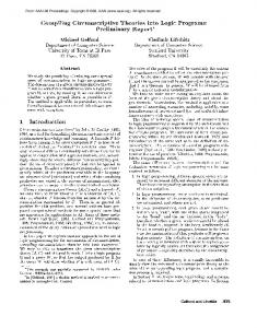
2. Problem expression The problem of the laminar fluid flow in a channel with an obstacle was considered (Figure 1). The solution to the problem was obtained for the following assumptions: • the flow field was considered between parallel walls of a channel with height H; • an obstacle was placed at distance l from the channel inlet; • the flows in the channel were considered when the obstacles were triangular or rectangular with width s and height h; • the influence of the non-dimensional parameters, s/h and h/H, on the evolution of vortices behind the obstacle was studied. The geometry of the flow problem is presented in Figure 1.
Figure 1. Problem geometry: L – slit length, l – obstacle distance from slit entrance, H – slit height, h – obstacle height, y, z, – co-ordinate system axes
tq414c-e/330
24 III 2011
BOP s.c., http://www.bop.com.pl
Preliminary Calculations of Flow in Channel. . .
331
The following fluid flow parameters were taken to perform the calculations: L l H h v ̺ µ d1 d2
– slit length, L = 5m, – obstacle distance from slit entrance, l = 1, – slit height, H = 0.4m, – obstacle height h = 0.2m, rectangular obstacle with the width of s = 0.01, 0.03, 0.05m, triangle obstacle of 0.01, 0.03, 0.05m, – velocity, v = 0.002m/s, – density, ̺ = 1000kg/m3 , – dynamic viscosity, µ = 0.001Pa · s, – distance from slit entrance, d1 = 1.5m, – distance from slit entrance, d2 = 2m.
The non-dimensional values which characterize the geometry of the flow in a channel with a triangular and rectangular obstacle are presented in Table 1. Table 1. Non-dimensional values characterizing flow field geometry in channel s [m]
s/h
h/H
0.01
0.05
0.5
0.03
0.15
0.5
0.05
0.25
0.5
0.16
0.8
0.5
Numerical calculations were performed using a commercial solver, ADINA-F [7, 17]. As the flow is two-dimensional in the coordinate system as shown in Figure 1, partial differential equations [17] describing the flow have the following form: � � � 2 � ∂p ∂v ∂v ∂ v ∂2v ∂v (1) = − +η + v +w + ρ ∂t ∂y ∂z ∂y ∂y 2 ∂z 2 � � � 2 � ∂w ∂w ∂p ∂ w ∂2w ∂w (2) + +v +w = − +η ρ ∂t ∂y ∂z ∂z ∂y 2 ∂z 2 ∂v ∂w + =0 (3) ∂y ∂z where: v, w p ̺ µ
– – – –
components of water velocity to y axis, z [m/s], pressure in slit [Pa], water density [kg/m3 ], dynamic viscosity [Pa · s].
The boundary conditions imposed on the velocity are the following: • no slip on the top and bottom wall of the slot, • no slip on the surface of the obstacle. The calculations were performed assuming that the flow in the channel was unsteady, incompressible, viscous, two-dimensional, with zero mass forces, the outlet of the channel was unbounded, the fluid was water.
tq414c-e/331
24 III 2011
BOP s.c., http://www.bop.com.pl
332
M. Kmiotek and A. Kucaba-Piętal
3. Results of calculations The aim of the research was to analyze the influence of geometrical parameters characterizing an obstacle on the development of vortices in a channel. As has been mentioned before, the finite elements method and the commercial software package. ADINA-F 8.6 [7, 17] were used for numerical solutions of the Equations (1)–(3). This package also allows performing an analysis of Fluid Structure Interactions. The research was conducted for six instances of a slit bounded by two parallel walls, where an obstacle of a different shape was placed at distance l. In the first three cases the obstacle was of a triangular shape, in the next three cases the obstacle was rectangular. For calculation purposes the flow area was divided into 2D fluid elements (Figure 2). The calculations were made on structural, four-node grids. (a) (b)
Figure 2. Examples of grids used for calculations: (a) 9491 nodes and 9200 finite elements; (b) 9701 nodes and 9400 finite elements
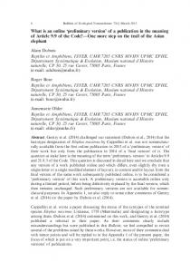
The velocity distribution for all six cases of the above described channel flow was obtained for various Reynolds Numbers Re, which can be defined as follows: ρvH Re = (4) µ In Figure 3 the velocity distributions for Re = 20, 100, 800 are presented. (a)
(b)
(c)
Figure 3. Velocity distribution v [m/s] in channels with obstacle: (a) triangular and rectangular s/h = 0.05 for Re = 800; (b) triangular and rectangular s/h = 0.15 for Re = 100; (c) triangular and rectangular s/h = 0.25 for Re = 20
tq414c-e/332
24 III 2011
BOP s.c., http://www.bop.com.pl
Preliminary Calculations of Flow in Channel. . .
333
It can be noticed that when the obstacle is placed in a channel the picture of the flow is deformed, and as can be expected, the area of the vortices development is behind the obstacle, except for Re = 20 or lower. In Figures 4 and 5 the graphs of the components of the longitudinal velocity vy just behind the triangular and rectangular obstacle for Re = 100 are presented. (a)
(b)
Figure 4. Profiles of longitudinal velocity vy in channels with triangular obstacle for: (a) d1 = 1.5m and (b) d2 = 2m
tq414c-e/333
24 III 2011
BOP s.c., http://www.bop.com.pl
334
M. Kmiotek and A. Kucaba-Piętal (a)
(b)
Figure 5. Profiles of longitudinal velocity vy in channels with rectangular obstacle for: (a) d1 = 1.5m and (b) d2 = 2m
When to compare the profiles of components with longitudinal velocity vy it can be observed that the velocity profiles are of a similar nature for the triangular obstacles. The width of the rectangular obstacle influences bigger changes in the velocity field than for the triangular obstacles, i.e. the profiles are not symmetrical and the velocity maximum shifts towards the upper wall of the obstacle.
tq414c-e/334
24 III 2011
BOP s.c., http://www.bop.com.pl
Preliminary Calculations of Flow in Channel. . .
335
(a)
(b)
(c)
(d)
(e)
Figure 6. Velocity vectors v [m/s] during flow in slit with rectangular obstacle of s/h = 0.25: (a) t = 1000s; (b) t = 2000s; (c) t = 3000s (d) t = 4000s; (e) t = 5000s
Vortices evolution – velocity vectors on the example of flow in a slit with the rectangular obstacle with the width of s = 0.05m for Re = 800 are shown in Figure 6. The velocity field for one of the channels tested experimentally and discussed in article [22] was calculated using the ADINA package presented in this paper to verify the numerical computation. The structure of the flow in a rectangular channel unilaterally narrowed depending on the size and width of constriction obstacles has been analyzed in [22]. The fluid flow was studied experimentally using laser anemometry and confirmed by visualization carried out by the authors. For the channel with a rectangular barrier with width s = 0.16m and constriction h/H = 0.5 for Reynolds number Re = 2000 (considered in paper [22]) numerical computations were performed using the ADINA package. The obtained results of the calculated velocity are shown in Figure 7. The velocity profiles at distance d1 were compared with the experimental data from [22] and are shown in Figure 8.
Figure 7. Velocity v [m/s] in channel with rectangular obstacle (width s = 0.16m for Re = 2000)
4. Conclusions The results of the numerical simulation of the unsteady flow in a channel showed that the geometry and shape of an obstacle influenced the flow picture and the vortices development in a channel. An increase in the Reynolds number made
tq414c-e/335
24 III 2011
BOP s.c., http://www.bop.com.pl
336
M. Kmiotek and A. Kucaba-Piętal
Figure 8. Profiles of flow velocity in unilaterally narrowed rectangular duct, Re = 2000 for experimental results [22] and for results of numerical calculations using ADINA package
the area of the direct disturbances behind the obstacle longer. For the rectangular obstacles, an increase in their width caused bigger changes in the velocity field than for the triangular ones. The next stage of research will be modeling the heat flow and an analysis of the Fluid Structure Interactions in the channel with an obstacle.
References [1] [2] [3] [4] [5] [6] [7] [8] [9] [10] [11] [12] [13] [14] [15]
Cichoń Cz 2005 Computational Methods, Selected Issues, WPS, Kielce Croce G and D’Agaro P 2005 J. Phys. D: Applied Physics 38 1518 Fujimoto S and Okita Y 2010 J. Turbomachinery 132 Gorji-Bandpy M, Soleimani S and Jafari B 2008 Int. J. Dynamics of Fluids 4 (2) 93 Grybos R 1998 Fundamentals of Fluid Mechanics. Turbulence, Numerical Methods, Technical Applications, PWN, Warsaw Kazimierski Z 2007 Rotation Fluid in Nature and in Machines and Equipment, WPL, Lodz Kmiotek M 2008 Scientific Bulletin of Chełm, Section of Mathematics and Computer Science 1 151 Kosma Z and Noga B 2006 Chem. Proc. Eng. 27 761 Kucaba-Piętal A 2004 Applicability of Micro Polar Fluid Theory to Modeling Microflows, OWPR, Rzeszow Kleiber M 1995 Technical Mechanics, Computer Methods of Mechanics, PWN, Warsaw Makino S, Iwamoto K and Kawamura H 2008 Int. J. Heat and Fluid Flow 29 602 Kołodziej J A 2003 Selected Topics in Fluid Mechanics in Terms of Computer, WPP, Poznan Makino S 2008 Progress in Computational Fluid Dynamics 8 397 Oztop H F, Varol Y and Alnak D E 2009 Int. Comm. Heat and Mass Transfer 36 878 Poh-Seng L, Garimella S V and Liu D 2005 Int. J. Heat and Mass Transfer 48 1688
tq414c-e/336
24 III 2011
BOP s.c., http://www.bop.com.pl
Preliminary Calculations of Flow in Channel. . .
337
[16] Reza K 2008 Simulation of Flow in Continuum-Transition Regime in Stepped-Microchannels Using Burnett Equations, ICNMM 2008-62150, Darmstadt, Germany [17] ADINA-F Tutorial, http://www.adina.com/tutorials.shtml [18] Sztaba G 2006 Chem. Proc. Eng. 27 803 [19] Ulbrich R 2006 Image Processing Method for the Estimation Flow of Gas – Liquid in the Elements of Shell and Tube Heat Exchanger, OW, Opole [20] Thanhtrung D, Jyhtong T and Jianncherng Ch 2010 Proc. Int. Multiconference of Engineers and Computer Scientists, Hong Kong, III, pp. 17–19 [21] Topoczewski A 2003 Sanitary Installations 2 (7) 27 [22] Jeżowiecka-Kabsch K 2002 Chem. Proc. Eng. 23 481
tq414c-e/337
24 III 2011
BOP s.c., http://www.bop.com.pl
338
TASK QUARTERLY 14 No 4
tq414c-e/338
24 III 2011
BOP s.c., http://www.bop.com.pl