This allows us to describe the channel only partially, e.g. as dominated by multipath-like ..... Networks And Internet Appliances Shape Service. Provider Access ...
S. Galli, T. Banwell, “Modeling the Indoor Power Line Channel …,” IEEE Consumer Communications and Networking Conference, CCNC’04, Jan. 2004
MODELING THE INDOOR POWER LINE CHANNEL: NEW RESULTS AND MODEM DESIGN CONSIDERATIONS Stefano Galli, Thomas C. Banwell Telcordia Technologies, Inc., 445 South Street, Morristown, NJ 07960, USA . Abstract – Considerable effort has been recently devoted to the determination of accurate channel models for the Power Line (PL) environment, both for the indoor and outdoor cases. The common denominator (and limitation) of the known and previously published models is the particular type of approach followed. In fact, until now, the PL channel (PLC) has been treated from a mere phenomenological or statistical point of view. This allows us to describe the channel only partially, e.g. as dominated by multipath-like effects, and prevents us from unveiling particular properties of it. In this paper, we report results about a new approach to the modeling of the PLC based on Multiconductor Transmission Line (MTL) theory. The need for an MTL approach arises from the fact that indoor power cables consist of three conductors, and not just two as for classical twisted-pair and coaxial cable cases. This approach allows us to include wiring and grounding practices dictated by the United States National Electric Code (NEC). On the basis of this modeling it is here revealed that the PLC is a more deterministic media than commonly believed. Moreover, it is also possible to prove an interesting symmetry property of the PLC that was previously unknown: the PLC, regardless of its topology, exhibits the same transfer function when driven from either side, provided that the source and load impedances are the same.
I.
INTRODUCTION
There is today a renewed interest in PL communication, and several field trials are presently being carried out throughout the world [2]. The rationale behind providing high bit-rate data services exploiting the power grid resides in the vast infrastructure in place for power distribution, and the penetration of the service could be much higher than any other wireline alternative. Other broadband alternatives such as xDSL and cable modems have only reached about 10% of US households, even though 60% of households are already connected to the Internet. There is a tremendous opportunity for PL communications to bridge this gap. There is also growing interest in the prospects of re-using in-building PL cables to provide a broadband Local Area Network within the home or office [3]. The major advantage offered by PL-based home-networks is the availability of an existing infrastructure of wires and wall outlets so that new cable installation is averted. Since PL technology appears to be more mature for the home-networking scenario than for the broadband access one, we will focus on the modeling of the indoor PLC and, in particular, on its transfer function.
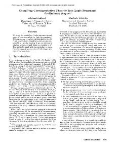
Several approaches have been followed for characterizing the PLC [4]-[7]. In particular, an interesting approach is to describe the PLC as if it were affected by multipath effects [5], [6]. There have also been attempts in the past to model the PLC as a two-conductor transmission line (TL) [7]. These approaches share a common deficiency in that they are only able to partially describe the underlying physics of PL signal propagation and, therefore, do not allow the unveiling of general properties or any embedded determinism of the PLC. Moreover, the multipath approach is based on a parametric model where the many parameters can be estimated only after having measured the PLC impulse response, thus limiting the capability of a priori channel modeling. The unavailability of a model that fully describes signal propagation along PL cables led the PL community to often reach overly pessimistic conclusions: the PLC is impossible to model a priori, does not allow for the superposition of effects, and has very little or no determinism embedded in it [8]. In particular, these analyses neglected two major points: 1) the presence of a third conductor, which makes the problem one of MTL theory; 2) the effects of particular wiring and grounding practices. A new approach to the characterization of the PLC based on MTL theory is here described. Analytical details about this approach can be found in [1]. II. RESIDENTIAL AND BUSINESS INDOOR WIRING TOPOLOGIES Power cables used for single-phase indoor wiring are comprised of three or four conductors in addition to the ubiquitous earth ground. These include “hot” (black), “return” (white), safety ground and “runner” (red) wires, all confined by an outer jacket that maintains close conductor spacing. Residential and commercial premises PL networks usually comprise a service panel feeding multiple branching paths that include receptacle or outlet circuits, fixed or embedded appliances and lighting circuits (see Figure 1). While the “white” return wires and safety grounds are isolated throughout all distal network branches, the United States National Electric Code (NEC) mandates that the return (white) and ground cables should be connected together or “bonded” at the service panel via a shunt resistance RSB. The black wires are each fed via separate circuit breakers while the white wires connect to the mains transformer return (RTN) via a common terminal block. The safety grounds are connected to earth ground via a second terminal block. Element RSB represents a low shunt resistance between the ground and
S. Galli, T. Banwell, “Modeling the Indoor Power Line Channel …,” IEEE Consumer Communications and Networking Conference, CCNC’04, Jan. 2004
return paths, referred to as “bonding”. There is substantial mode coupling created by the electrical path through RSB, which has been largely ignored in previous models of indoor PL links. III. MULTICONDUCTOR ANALYSIS OF POWER LINE CABLES A three-conductor cable supports six propagating modes (TEM approximation), three spatial modes (differential, pair and common modes) each for two directions of propagation. The differential mode (or balanced mode) current Idif represents an “odd-mode” with current confined to the white and black wires and is generally the desired signal. The pairmode (or longitudinal mode) current Ipr represents an “evenmode” with current flowing between the safety ground wire and the white/black wires “tied together”. The two modes Idif and Ipr are well confined to the cables and consequently exhibit low attenuation. The third common mode current Icm represents overall cable current imbalance, which creates a current loop with earth ground. The differential mode current is almost always the functional current responsible for carrying the desired data signal along the line. It is possible to excite only a differential propagating mode along a TL by differential signaling. However, if there are imbalances or asymmetries between the conductors, common mode components may arise even when the conductors are differentially driven. The presence of common mode currents on a cable does not inherently degrade the integrity of differential mode data signals. However, if mechanisms exist where energy can be transferred from common mode to differential mode, then the common mode current can become a dominant interference signal. This phenomenon is called mode conversion or mode coupling. Building on a successful model for signal propagation in multi-pair category 5 UTP links [9] utilizing MTL modal decomposition [10], the new approach described in [1] takes into account important grounding practices imposed by the United States NEC. MTL analysis involves breaking down a system of N conductors and a ground into N simple transmission lines (TL), each of which corresponds to a mode of propagation. Therefore, signals at the input of an MTL are broken down into modal components and sent down the proper modal TLs. For the particular case of three-conductor PL cables, it has been found that only two of the three modes of propagation are dominant [1]. One of the main advantages of the proposed approach is that it allows us to compute a priori and in a deterministic fashion the transfer function of any PL link by using transmission matrices as is routinely done for the twisted-pair environment. To achieve this result, an equivalent circuit for the two dominant propagating modes along the cables is derived using MTL decoupling techniques. This will lead us to a model consisting of two coupled circuits representing the propagation and interaction of the two dominant modes. In particular, the first circuit accounts for differential-mode propagation while the second circuit accounts for the excitation and propagation of the pair-mode, which is the second dominant mode and arises prominently with certain grounding practices. This second circuit
represents what we refer to as the “companion model.” These two circuits are coupled through a transformer located at the principal point of mode coupling, i.e. the ground bonding. The presence of mode coupling and the excitation of the pair-mode have been neglected in previous studies. The two circuit models obtained on the basis of MTL decoupling theory (the differential and the companion circuits) can also be represented in terms of cascaded two-port networks (2PNs) strongly coupled through a single transformer. Once the equivalent 2PN representation is obtained, it is possible to represent the PL link by means of transmission, or ABCD, matrices, exclusively. This approach will allow us to compute analytically and a priori the transfer function of any indoor PL link, including in the model the topology and the specific wiring practices. Finally, as shown in [1], it is possible to mathematically prove that one of the consequences of a 2PN modeling is that the PLC, regardless of its topology, is isotropic, i.e. exhibits the same transfer function from either side, under the sole condition that the output impedance of the transmitter is equal to the input impedance of the receiver. It is worth pointing out that this symmetry property cannot be proven using the Reciprocity Theorem, which states that any transfer function with the dimension of impedance or admittance remains unchanged if the points of excitation and response are interchanged. In fact, the Reciprocity Theorem holds for transfer functions with the dimension of a transimpedance or a transadmittance and does not hold for dimensionless transfer functions. Similar considerations also apply to the telephone channel [11]. IV. EXPERIMENTAL RESULTS: ISOLATION OF RESONANT MODES AND SYMMETRY OF THE TRANSFER FUNCTION We are building a networked “smart” home in one of our labs. This home will be equipped with several wired and wireless networks such as Ethernet, IEEE 1394, IEEE 802.11, and HomeRF. It will also be a EIA/CEA 851 VHN Home Network compliant test bed, where VHN is a home network standards effort under the auspices of the Electronic Industries Alliance (EIA) / Consumer Electronics Association (CEA). Power cables have been deployed in such a way that several different topologies can be investigated. Transmission measurements were performed with a network analyzer using balun transformer coupling at the locations X and Y. For our experiments, we chose an indoor wiring model having two branches with five outlets and a breaker box as shown in Figure 2. The equivalent circuit model derived on the basis of the model proposed in [1] is shown in Figure 3. A. Isolation of Resonant Modes Swept frequency transmission measurements were performed from 0.3-30MHz. 1:√2 balun transformers were used with resistor matching networks to interface the 50Ω network analyzer ports to the test points. Experiments were conducted with various values chosen for RSB, R4, R2, and matched sending and receiving impedance (RY = 140Ω). By selectively disconnecting the bonding shunt, 15ft, 25ft and 60ft branches, 12 distinct topology variations can be
S. Galli, T. Banwell, “Modeling the Indoor Power Line Channel …,” IEEE Consumer Communications and Networking Conference, CCNC’04, Jan. 2004
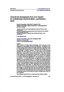
obtained. Figure 4 summarizes the observable notches for all 12 distinct topologies. The box labeled “B” indicated the presence of bonding and the diamond indicates the breaker box where the mains feed is (eventually) connected; the mains feed is always shorted, except for the eighth topology where it is open. The second bridged tap may be unterminated or terminated in resistance R2 = 140Ω. The first topology (first row) is the complete topology shown in Figure 2, with R4=0, R2 = 140Ω, RSB=2Ω. By examining Figure 4, we notice that the ground bonding shunt (eleventh topology) creates dips at 3.3, 9.9, 16.7 and 23.3 MHz; R2 = ∞ (tenth topology) creates dips at 7.0 and 21 MHz, the 15ft branch (ninth topology) creates a 11.4 MHz dip, and the mains feed with R4=0 (seventh topology) creates dips at 4.8, 9.8, 14.9, 19.8 and 24.8 MHz. It is interesting to note that if the link contains the unterminated 15ft branch (the first bridged tap in Figure 2o, the transfer function always contains a notch at 11.4 MHz. Similarly, in all the topologies containing the 60 ft mains feed with R4=0, notches at 4.8, 9.8, 14.9, 19.8 and 24.8 MHz are always present. Also, in all the cases where the second bridged tap is unterminated (R2 = ∞) dips at 7.0 and 21 MHz are always present. On the basis of these experiments, we can say that if a certain feature, e.g. a bridged tap, the bonding, the mains feed, etc., is always present in the link, then corresponding notches will be always present in the transfer function. B. Symmetry of the Transfer Function Figure 5 shows the measured transfer function of the link in Figure 2 from (X) to (Y) and from (Y) to (X), with R4=0, RSB=2Ω. and R3=∞. The response is nearly identical in both directions with matched sending and receiving impedance, thus confirming the PLC symmetry property proven in [1]. V. EXPLOITATION OF THE DETERMINISM PRESENT IN THE POWER LINE CHANNEL A. Mapping the Network Although some appliances in the home may be switched on or off several times during the day, some appliances are usually always on and their input impedance varies slowly during the day. Some other features of the network can be considered constant during the day: the presence of the mains feed, the bonding, some unused plugs in certain rooms, etc. Therefore, it is not unreasonable to assume that the transfer function between two PL modems located at two home network nodes may always exhibit notches at certain frequencies. This suggests the possibility that PL modems could effectively try to map particular features of the entire PL home network. This mapping could be accomplished adaptively by continuously transmitting training sequences or by embedding into the modems some a priori information on the topology of the in-home PL wiring. The network maps obtained for some particular states of the link can be stored and appropriately utilized. Over time, it is likely that all the states of the channel are encountered so
that the PL modem can infer and, therefore, exploit, the actual state of the network on the basis of the estimated channel transfer function, e.g. with a look-up table. The obtained network mapping could be exploited in several ways. For example, by determining which are the notches always present for a particular configuration and state of the home PL link, thus determining in which frequency band it is always better not to transmit information. Additionally, since some notches may be present or not depending on the states of the channel, the availability of a look-up table would allow the PL modem to quickly decide which modulation/coding technique for that particular network state is more appropriate. B. Appropriate Modulation Techniques The results of Sect. IV suggest that the transfer function of any PL link in the home is likely to contain several notches due to the always present ground bonding and mains feed. This is fundamentally different from the case of a home network based on inside telephone wiring (HomePNA), a case in which the frequency transfer function will exhibit notches if and only if bridged taps were present (see, for example, the analysis in [3]). Channels that exhibit transfer functions such as the ones shown in Figure 5 introduce strong ISI, thus requiring powerful nonlinear equalization techniques, combined with adaptive modulation and precoding techniques. As far as precoding techniques, the knowledge that the channel is symmetric opens the door to information theoretic considerations on optimal transmission when the channel is known at the transmitter. For example, treating known ISI as interference known at the transmitter allows us to use “dirty paper” coding techniques. The choice of Discrete Multitone (DMT) modulation may also be an appropriate one for indoor PLC. In fact, DMTbased PL modems can adaptively change the spectral efficiency in each sub-band, depending on the particular state of the network, and avoid loading those carriers located in sub-bands containing deep notches. Moreover, since a node in the network that receives data must also estimate the transfer function of the channel, it can perform optimal bit-loading adaptively, exploiting the knowledge that the channel in the reverse direction is the same. As a final remark, it is important to note that symmetry of the transfer function is not really equivalent to symmetry of the channel. In fact, in the PL environment, nodes in a home network may be affected by different kind of noises and, therefore, the knowledge of the state of the channel at the transmitter is not actually “perfect”. VI. CONCLUSIONS The common denominator (and limitation) of the previously published models for the PL environment is the particular type of approach followed. Until now, the PLC has been treated from a mere phenomenological or statistical point of view. These approaches allow us to describe the channel only partially, and prevent us from unveiling particular properties of it. In this paper, we described a novel approach to the problem of indoor PLC modeling, based on MTL theory and modal decomposition [1]. The MTL approach followed
S. Galli, T. Banwell, “Modeling the Indoor Power Line Channel …,” IEEE Consumer Communications and Networking Conference, CCNC’04, Jan. 2004
here leads us to a model consisting of two coupled circuits representing the propagation and interaction of the two dominant modes, the differential and the pair-mode. On the basis of this circuit model it is possible to obtain an equivalent PLC model expressed in terms of cascaded 2PNs. This modeling, reminiscent of the classical modeling of twisted pairs, provides us with a convenient way to compute the transfer function of any indoor PL link and, at the same time, allows us to unveil special properties of the PLC not reported earlier. VII. REFERENCES [1]
[2]
[3]
[4]
S. Galli, T. Banwell, “A Novel Approach to Accurate Modeling of the Indoor Power Line Channel – Part I and Part II”, to be submitted, 2003. S. Galli, A. Scaglione, K. Dostert, “Broadband is Power: Internet Access Through the Power Line Network”, IEEE Communications Magazine, vol.31, no.5, May 2003. S. Galli, K.Kerpez, S. Ungar, D. Waring, “Home Networks And Internet Appliances Shape Service Provider Access Architectures”, IEEE International Symposium on Services and Local Access, ISSLS’00, Stockholm, Sweden, 18-23 June, 2000. H. Philipps, “Modeling of Power Line Communications Channels”, Proceedings of the IEEE International Symposium on Power Line Communications and its Applications, ISPLC’99, Lancaster, UK, April 1999.
[5]
M. Zimmermann, K. Dostert, “A Multipath Model for the Power Line Channel”, IEEE Trans. Commun., vol. 50, no. 4, pp.553-559, April 2002. [6] H. Philipps, “Development of a Statistical Model for Power Line Communications Channels”, Proceedings of the IEEE International Symposium on Power Line Communications and its Applications, ISPLC’00, Limerick, Ireland, April 2000. [7] O.G. Hooijen, “On the Relation Between NetworkTopology and Power Line Signal Attenuation”, Proceedings of the IEEE International Conference on Power Line Communications and Its Applications, ISPLC’98, Tokyo, Japan, March 24-26, 1998. [8] P. Sutterlin, “A Power Line Communication Tutorial: Challenges and Technologies”, Proceedings of the IEEE International Conference on Power Line Communications and Its Applications, ISPLC’98, Tokyo, Japan, March 24-26, 1998. [9] T.C. Banwell, W.E. Stephens, “Line Code Selection for 155.52 Mb/s Data Transmission on Category 5 Cable Plant”, IEEE J. on Sel. Areas in Commun., vol. 13, no. 9 , Dec. 1995. [10] C.R. Paul, Analysis of Multiconductor Lines, Wiley & Sons, Inc., 1994. [11] S. Galli, “Exact Conditions for the Symmetry of a Loop”, IEEE Communications Letters, vol. 4, no. 10, October 2000.
SERVICE TRANSFORM ER SERVICE DROP
HOT
RTN
L2
L3
CIRCUIT BREAKERS
BLK
BLK
W HT
W HT R SB
GND
R SB GND
Figure 1 Diagram of a typical service panel with four circuit breakers. Two branch cables are explicitly shown along with two additional loads.
S. Galli, T. Banwell, “Modeling the Indoor Power Line Channel …,” IEEE Consumer Communications and Networking Conference, CCNC’04, Jan. 2004
MAINS
TX
(X)
RCV
(Y)
60ft 6/2
25ft 14/2
25ft 14/2
25ft 14/2
SERVICE PANEL
15ft 14/2
25ft 14/2
Figure 2 Physical model used in our experiments composed of a TDR head driving two sections of 14/2 NM cable connected in series. Programmable shunt impedances are placed at the cable’s junction.
DIFFERENTIALMODE VX
36ns 140Ω
R4
96ns 50Ω
36ns 140Ω
RY
36ns 140Ω
VY Vdif ZS=140Ω
22ns 140Ω
2Vpr
36ns 140Ω
4RSB
VS
FE
BONDING
R3 ½Vdif
RSB
35ns 58Ω 35ns 58Ω 21ns 58Ω
35ns 58Ω
Vpr 35ns 58Ω
PAIR-MODE COMPANION Figure 3
The final circuit model of the power line link used in Figure 2: differential circuit model (upper section) and its “companion model” (lower section). The modal transformer characterizing the bonding shunt is also shown.
S. Galli, T. Banwell, “Modeling the Indoor Power Line Channel …,” IEEE Consumer Communications and Networking Conference, CCNC’04, Jan. 2004 (X)
(Y)
B
B
B open
B
0
5 Figure 4
10
15
Frequency in MHz
20
25
Table summarizing resonant dips for all twelve considered topologies.
TRANSMISSION GAIN ( dB )
0 HXY
HYX
-10
-20
-30
FREQUENCY ( MHz) Figure 5
Plot of the measured transfer functions (from X to Y, and from Y to X) for the topology in Figure 2.