functionality. Modern user interfaces in these new systems offer significant
benefits over their ... John C. Knight1 and Susan S. Brilliant2. 1 University of
Virginia, ...
Preliminary Evaluation of A Formal Approach to User Interface Specification John C. Knight1 and Susan S. Brilliant2 2
1 University of Virginia, Charlottesville, VA 22903, USA Virginia Commonwealth University, Richmond, VA 23284, USA
Abstract. In this paper we report on a research project in which the user interface for a research nuclear reactor was specified using a combination of formal notations. The goal of the project was to evaluate the use of a combination of techniques and to assess their utility in specifying a user interface for a non-trivial safety-critical application. We conclude that the techniques worked well and scale up easily to the size of the application studied.
1
Introduction
User interfaces can be very complex. The user interface in a modern nuclear power plant in the U.S.A., for example, might include hundreds of illuminated indicators, digital and analog gauges, strip-chart paper displays, switches, rotary controls, and so on. Such systems usually require several human operators to maintain proper control. In many applications, computer-based control systems are replacing systems based on older technology to increase flexibility, speed up operation, and enhance functionality. Modern user interfaces in these new systems offer significant benefits over their electromechanical counterparts. These benefits include the use of new devices such as voice input, the provision of new display concepts such as threedimensional visualization, and new analysis capabilities such as filtered and time-history presentation of signals [12]. These new user-interface capabilities bring with them a variety of challenges including proper ergonomic design and reliable software implementation. These challenges have to be addressed in order to develop safe systems [16] because the user interface is a safety-critical element of a control system. If a display contains an error, such as incorrect data or mislabeling of an object, an accident might occur when the operator acts on this incorrect information. Also, if the interface does not respond to user actions as the operator expects, the result might also be unsafe. Examples of such problems have already occurred [17]. An incident reported recently that occurred in a nuclear power plant highlights the importance of correct and understandable specifications [22]. The overhead annunciator system in the control room (procured from a major vendor) stopped processing and sounding messages without any indication of failure. The system failed when the primary process that sorted the alarm input buffer into a time sequenced output buffer aborted. Software that displayed the data and actuated the overhead annunciator windows continued to operate and so the system appeared to be operating. Root-cause investigation revealed that the vendor thought the operating system would force a
restart if any process aborted (it does not), and that a watchdog timer would protect the system (it does not). In general, the development of user interfaces is a difficult and important problem. Because many errors in computer systems can be traced to defects in their specifications, a critical aspect of user-interface development is the specification of exactly what the user interface is to do. As safety-critical applications rely more heavily on increasingly complex user interfaces, the need to specify the user interface precisely and correctly in such systems becomes essential. Despite the importance of specification, in practice user interfaces are rarely specified with any degree of care. Most user interfaces evolve from an initial prototype implementation derived from an informal and incomplete description provided by application experts to a final implementation for which there is no specification. This evolution takes place as a series of iterations in which the implementation is demonstrated, evaluated by the application experts, and then enhanced. This is not an ideal situation and we hypothesize two reasons why it has arisen. The first reason is that the formal specification of a user interface requires a massive amount of detail if it is to be done properly. For example, to specify precisely the details of a pull-down menu on a computer screen requires detail such as colors, shape and appearance, and location as well as all the semantics associated with selecting a menu item. The second reason that we hypothesize to explain why user interfaces are rarely specified carefully is the variety of material that has to be specified. No single formal specification language has the facilities to describe all that is needed, and very few have any kind of animation mechanism that would permit application engineers to check that what is described is what they require. In two previous papers [3, 7] we have described an early version of an approach to formal specification of user interfaces that we have developed. In this paper, we present a preliminary evaluation of the approach based on the development of formal specifications for the user interfaces of two safety-critical systems: a medical robot and a nuclear reactor [6]. This latter system is the subject of a case study in which we are developing a prototype experimental (non-operational) control system for the research nuclear reactor at the University of Virginia. Examples from this project are used for illustration in this paper. The reactor specification was developed informally because its creation drove the refinement of the techniques described here. The requirements for the user interface were determined by examination of existing documentation, observation of the current system in operation, and extensive discussion with reactor operators and staff. Several reviews of different aspects of the specification have been held, and the user interface has been connected to a high-fidelity reactor simulator for user evaluation. All of these activities were informal and in no way validate the specification. Evaluation is ongoing. The specification approach that we are using employs three existing formal notations in an integrated framework—no new notations are involved. Our goals with the project that we describe are twofold. The first is to determine the capabilities that can be achieved and determine the difficulties raised by integrating more than one formal
notations. The second goal is to evaluate the utility of the notations themselves in specifying the user interface for a non-trivial safety-critical application. In other words, how well do these techniques scale-up? We begin with an overview of the reactor application, and we follow this with a summary of the current version of the approach to specification that we have used. We then present examples of the specification taken from the reactor case study. These examples are followed by details of our evaluation criteria and our current evaluation results. Finally, we present our conclusions.
2
University Of Virginia Reactor
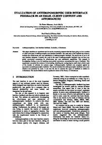
The case study application providing most of the information for the evaluation of the specification technique is the University of Virginia Reactor (UVAR). This is a research reactor that is used for the training of nuclear engineering students, service work in the areas of neutron activation analysis and radioisotope generation, neutron radiography, radiation damage studies, and other research [23]. As part of a research program in software engineering, a digital control system is being developed for the UVAR and is currently in the specification stage.1 The UVAR is a “swimming pool” reactor, i.e., the reactor core is submerged in a very large tank of water. The water is used for cooling, shielding, and neutron moderation. The core uses Low Enriched Uranium (LEU) fuel elements and is located under approximately 22 feet of water on an 8x8 grid-plate that is suspended from the top of the reactor pool. The reactor core is made up of a variable number of fuel elements and in-core experiments, and always includes four control rod elements. Three of these control rods provide gross control and safety. They are coupled magnetically to their drive mechanisms, and they drop into the core by gravity if power fails or a safety shutdown signal (known as a “scram”) is generated either by the operator or the reactor protection system. The fourth rod is a regulating rod that is fixed to a drive mechanism and is therefore non-scramable. The regulating rod is moved automatically by the drive mechanism to maintain fine control of the power level to compensate for small changes in reactivity associated with normal operations [23]. The heat capacity of the pool is sufficient for steady-state operation at 200 kW with natural convection cooling. When the reactor is operated above 200 kW, the water in the pool is drawn down through the core by a pump via a header located beneath the grid-plate to a heat exchanger that transfers the heat generated in the water to a secondary system. A cooling tower located on the roof of the facility exhausts the heat and the cooled primary water is returned to the pool. The overall organization of the system is shown in Fig. 1. The existing reactor control system, shown in Fig. 2, is comprised primarily of analog instrumentation that is used by the reactor operators to monitor and regulate operating parameters over all ranges of operation, from start-up to full power. A firstgeneration of the digital control system will replicate the functionality of the existing control console. The majority of that functionality is the display of process variables
1. At present there is no intention of putting the digital control system into operation.
Safety Rods
Cooling Tower
Regulator Rod
Actuator Commands
Heat Exchanger
Pool
Control Console
Sensor Data
Experiments
Reactor Core Header Pump
Fig. 1. The University of Virginia reactor system. including gross output, neutron flux and period, temperature difference between water entering the core and water leaving the core, control and regulating rod positions, primary system flow, and pool water level. The control console also provides facilities for operator input to the reactor system, including control of the regulating and control rods, a means to test instrumentation, and responses to unsafe conditions.
3
Specification Approach
A user interface is a complex entity; specifying such an entity is correspondingly complex. The interface is far more than the graphics, the operator commands, or even these two combined. Informally, the items that have to be defined if a specification is to be in any sense complete include everything that is presented to the operator, everything that the operator can do to the interface, everything that it would be erroneous for the operator to do together with the actions that are required in each case, and the exact meaning of each input that the operator can enter. In a comprehensive approach to userinterface specification, all of the these aspects need to be addressed, and the specification technique(s) used must deal with each aspect completely and consistently. Formal specification of user interfaces is not new. Various texts [5, 10] and surveys [2] have been prepared, and many research contributions published. Some of the
Fig. 2. Primary part of the existing main control console of University of Virginia reactor. existing work has been focused on problems such as specifying the graphical element of a user interface [1] or the details of the valid interactions [15, 20]. Other work has been concerned more with the tools needed to develop interfaces rapidly and accurately [18]. Such tools can be thought of as application generators controlled by formal notations. An advantage of the use of such tools is that they permit exploration of ergonomic issues associated with user interfaces. Our concern with the work described in this paper is with the precise specification of all aspects of the user interface for safety-critical systems. We are seeking specification with the greatest possible accuracy rather than rapid or flexible generation, and we are interested in a rather specialized area of application rather than general applicability. We also assume that ergonomic analysis is performed separately. In other words, we expect that ergonomic analysis will be undertaken at appropriate points by appropriate experts and that our task is to specify and analyse the resulting requirements. It could be argued that errors in the user interface of a safety-critical system, such as a nuclear reactor, are not themselves especially important because a protection systems is present (in principle) in the control system. A defective or omitted command should not lead to a hazard because the protection system will intervene. Although this will often be the case, protection systems usually only guard against the most catastrophic of situations and plenty of damage can be done within the range of operations accepted by the protection system—and protection systems do not always work. The position taken in the work described here is that the user interface should be viewed as
a critical element of the system and not impose an additional safety burden on other elements of the system. The specification approach we use builds on a view of the user interface introduced by Foley in 1974 [9]. This view models the interface as a dialog between the operator and the computer system carried out in a fixed interaction language. The specification problem is to define this language completely and accurately. In practice, the dialog cannot be defined just in terms of the inputs to be received from the operator since responses from the computer system change the state of the user interface and thereby change the operator inputs that are valid. Defining the interaction language using just one of the available formal specification notations is certainly possible but extremely difficult. It requires, for example, that a graphic screen be modelled using a mechanism such as a sequence of pixels if another notation, such as a picture is not to be used. Our approach, therefore, uses several different formal languages—each one suited to the part of the specification for which it is used. 3.1 Structure of the Specification In practice, the dialog between the operator and the computer system takes place in a set of languages—in effect, the operator is engaged in a set of sub-dialogs going on in parallel. In the alarm system for the UVAR, for example, an alarm can be signalled and possibly dealt with by the operator whilst he or she is adjusting control rod heights for a separate purpose. There are in effect two separate sub-dialogs going on in that case which take place in two separate if somewhat simple interaction languages. These languages are not entirely separate, however. In many circumstances, actions taken in one sub-dialog can affect the possible actions in another. In the UVAR alarm system, for example, a scram alarm forces the reactor to be shut down thereby limiting the possible actions in most other sub-dialogs. In our specification approach, each member of the set of languages required for the sub-dialogs is defined separately. The overall structure of each specification uses the three levels employed traditionally to describe formal languages: lexical, syntactic, and semantic levels. Each of these three levels is specified separately. Since different notations are used, a remaining issue is how the communication between these levels is defined. To provide this communication, we adopt abstract interfaces between the three specification levels, and also between the user interface specification and the application software specification. The role of the user interface is to accept and check user commands, and to update the material presented to the operator. The actual system functionality is implemented in the application software and that is assumed to be specified separately. However, it is essential that the interaction between the user interface and the application be defined. The overall structure of the specification, including the communication paths between specification levels and communication with the application itself, is shown in Fig. 3. The interface between the lexical and the syntactic levels is the same as that used in the formal definition of other languages—the lexical level defines a set of tokens, possibly including parameters, that are input to the syntactic level. Communication
User Accessible Devices
Productions
Commands
Present’n Interpreter Lexical Definition
Syntax Definition
User Actions
Semantic Definition Application Specification
Tokens
Fig. 3. User interface specification structure. from the application to the user interface is also accomplished using tokens thereby enabling state changes in the application to effect the necessary changes to the valid input sequences of the sub-dialogs. The application also generates a token to communicate a change in state that may need to be reflected in the user interface. Any changes that are required in the material presented to the user are recognized by the syntax level and invoked by the semantic level. These changes are specified by a set of messages that are generated by the semantic level and received and effected by the presentation interpreter (see Fig. 3). The interface between the syntactic level and the semantic level is borrowed from syntax-directed compiler technology. We specify the context-free syntax using BNF and each production in the specification is associated with a (possibly null) semantic action specified in Z so that for each production an appropriate action is specified. The semantic level communicates with the application by messages that are transmitted to the application after the recognition of valid sequences of user actions that require a response from the application. We summarize the details of our use of formal notations and how the inter-level communication is defined in the following sections. 3.2 Lexical Level The lexical level defines exactly how the user interface effects its dialogue, i.e., what instruments and controls the user sees and employs to control the system [8]. Part of the lexical level corresponds to the graphical items seen by the user on a computer screen. In our reactor example, precisely how the presence of an alarm is signalled to the operator—colored light, flashing light, bell, horn, voice, or a combination of these—is a lexical issue. A number of formal notations for specifying the lexical level of the user interface
have been proposed [1, 11, 14]. No matter what the notation, however, the specification of the lexical level is extremely complex. The source of the complexity lies in the sophistication of the available input and output devices. For example, in specifying a graphic user interface, all of the objects that are to appear on the screen must be described in complete detail. Some idea of the difficulty that this entails can be seen by considering the semantics of something as simple as a screen menu item. It is essential that the actions of the menu item be completely defined for all possible user actions including the following: depressing any mouse button over the item; releasing any mouse button over the item; releasing the mouse button over the item having depressed it elsewhere; typing text with the focus over a menu item; and so on. Rather than define an entire lexical specification using one of the existing notations for the graphic element of our specification approach, we have chosen to adopt a complete existing lexical specification framework and tailor it to our needs. The framework we employ is Borland’s Object Windows Library (OWL). This framework is defined using C++ classes and provides predefined specifications for all common graphic elements including command buttons, menus, bit-mapped graphics, and so on. OWL allows easy description of a graphic interface by inheriting from classes of graphic entities. Of great importance is the fact that the OWL documentation defines the base classes used in the specification precisely and hence provides the exact meaning of actions that manipulate those graphical objects (such as those involving the effect of pressing mouse buttons over a menu item mentioned above). In essence what we are doing is reusing an existing set of specifications and accepting whatever definitions they include. This is a very satisfactory trade-off, and there are a number of similar frameworks that could be used with similar results, e.g. TurboVision, Delphi, or Visual Age. The graphic component of a user interface specified with our approach consists of a simple C++ program that utilizes the library classes to define graphic objects. However, this relatively simple specification is accompanied by the library documentation and hence provides a complete specification of a complicated aspect of the interface. Any doubt that remains after the documentation is consulted can be resolved by regarding the C++ program as an operational definition. 3.3 Syntactic Level The syntax of the human-computer dialogue defines valid sequences of user input and computer output. The “dialogue” as we have noted is actually several sub-dialogues that proceed concurrently and that are interleaved arbitrarily. The syntactic level in our specification approach is documented with a set of context-free grammars with one grammar for each of the concurrent, asynchronous dialogues that might be taking place. The tokens that are input to each context-free grammar can be generated by three sources: • The lexical level. The user interface generates tokens in response to user manipulation of the interface.
•
The application program. Tokens arriving from the application program are the mechanism by which the application communicates with the user interface.
•
One of the other grammars in the set. This is the mechanism by which communication is achieved between the different languages that effect the sub-dialogs.
The concept of a multi-party grammar described by Shneiderman [21] is appropriate for representing grammars in which tokens are generated by more than one source. However, we have elected to use a conventional context-free grammar representation together with a naming convention to distinguish sources of tokens. The primary advantage of using conventional grammars is the ready availability of tools that provide automatic generation of syntax analyzers from the grammars. If one of these tools is used, the implementation is guaranteed to implement the specification if the tool is working correctly, and so verification of the translation is simplified. 3.4 Semantic Level In our specifications, we use Z [4, 13, 19] to define the user-interface context-sensitive syntax (i.e., the rules of syntax that are dependent on context) and the semantics. Z provides all the necessary mechanisms to define the various operations that are effected by the operator. It is important to keep in mind that the semantics to which we refer are just the semantics of the set of interaction languages. Once a command is deemed valid, its “meaning” in almost all cases is merely to send a message requesting some operation either to the application software itself or to the presentation interpreter. Thus important functional semantics, the reactor safety rules for example, are defined in the application specification.
4
An Example
Many aspects of the reactor control system user interface are straightforward. We focus here on one of the more complex subsystems in order to illustrate the division of labor and communication among the layers of the specification of the computerized control system. The subsystem we use is the safety control rod system. Recall that the three safety control rods (also called shim rods) provide gross control of reactivity and are one element of the safety system. For each of these control rods, the present operator’s console includes a set of four lights: • Engaged. This light indicates whether the rod is magnetically coupled to its drive mechanism. •
Up. This light indicates whether the rod is fully withdrawn.
•
Down. This light indicates whether the drive mechanism is at its lowest level.
Fig. 4. Rod controls provided by new digital system. This is just a small part of the user interface.
•
Seated. This light indicates whether the rod is fully inserted into the core, regardless of the position of the drive mechanism.
For each control rod, there are also displays indicating the rod height and the magnetic current to the rod attachment mechanism. To allow operator control of each rod, there are controls allowing the operator to set the magnet current and to raise and lower the rod. The operator can either move the rod by a small increment or move the rod continuously at a predetermined speed. The standard operating procedures in the current manual system allow the operator (a) to move the rods only when the neutron flux measurement exceeds a prescribed threshold (thereby indicating that the instrument is operating), and (b) to move two control rods simultaneously only if all three rods are raised less than 10 inches from their seated positions. These restrictions will be enforced by the software control system. Fig. 4 shows the small portion of the screen that results from executing the OWL lexical specification of the interface for the control rods, and Fig. 5 shows part of that specification. At this level the screen objects associated with the display of controlrod-related data are specified. For example, the rod heights are displayed in a digital format and are also shown graphically in an analog-style display for operator convenience. Either one of these could be used alone. An “up” and a “down” button are supplied for controlling the movements of each rod. Pressing and quickly releasing a button provides the incremental move action; holding the button down moves the rod continuously until the button is released. Another approach might have used a dialog box in which the direction of movement could be chosen, and then separate buttons might be provided to move incrementally, or start and stop the movement. Recall that the communication from the lexical level to the syntactic level uses tokens. For example, the action of depressing the left mouse key over the “up” button for a particular safety rod generates the token LEXStartRod with parameters indicating which safety rod button has been pressed and that the “up” action has been selected.
ControlRod::ControlRod (TWindow* parent, int Id, int Y, int W, : TWindow(parent, 0, 0)
float current, int X, int H)
{ up_button
top_light
= new ControlButton (this, "up", UP_BUTTON_TOP, BUTTON_HEIGHT); = new Light (LIGHT_LEFT TOP_LIGHT_RIGHT, "TOP", TColor::LtGray,
IDC_BUTTON_UP, BUTTON_LEFT, BUTTON_WIDTH,
TOP_LIGHT_TOP, TOP_LIGHT_BOTTOM, TFont("Arial", FONT_SIZE), TColor::LtBlue);
CurrentControl = new TVSlider (this, IDC_SLIDER_CURRENT, CURRENT_CONTROL_LEFT, CURRENT_CONTROL_TOP, CURRENT_CONTROL_WIDTH, CURRENT_CONTROL_HEIGHT);}
Fig. 5. Lexical specification fragment. The prefix LEX on the token is used to indicate that the lexical level is the source for this particular token. The parts of the control rod syntactic and semantic specification related to this action are shown in Fig. 6. Production 11 immediately preceding the Z schema StartRod will be applied when the LEXStartRod token is generated in response to the user action described above. The StartRod schema gives the semantic action associated with the application of this production. The precondition: (WhichWay? = Up÷Which? • RodUp)ˆ(WhichWay? = Down ÷Which? • RodDown) reflects the fact that the control rod can move up only if it is not already all the way up, and down only if it is not already down. If the precondition is satisfied, the output MsgToAP!, a message to the application, will send the operation code APStartRod with parameters to indicate that Which? is the control rod to be moved in the direction WhichWay?. The syntactic level imposes the required temporal ordering on user actions and system responses. For example, the context in which the LEXStartRod token can be recognized within the grammar enforces an ordering on the user actions in the usual sense associated with a context free grammar. In response to the message with the APStartRod operation code, the application will cause the indicated control rod to begin moving in the indicated direction. As the control rod moves, its new position will be communicated periodically to the user interface through the generation of a token by the application. This token is read by a
(1)
::=
(2) (3)
::=
|
(4)
::=
RodG2RodsEngaged
(5)
::=
ReactorG1InstrumentCheck
(6)
::=
+
(7) (8)
::=
|
(9) (10)
::=
|
(11)
::=
LEXStartRod (Which?, WhichWay?)
StartRod ¯RodControl Which? WhichWay? MsgToAP!
: : :
Rod Direction APRodMsg
(WhichWay? = Up ÷ Which? • RodUp) ˆ (WhichWay? = Down ÷ Which? • RodDown) MsgToAP! = (APStartRod, Which?, WhichWay?)
Fig. 6. Part of the specification associated with moving a control rod.
separate, concurrent grammar. The relevant part of this grammar and the associated semantic specification are shown in Fig. 7. The fact that this grammar fragment is part of a separate grammar from that used for control-rod movement allows the application to update the rod-height display any number of times between the user activities corresponding to the and nonterminals that must occur contiguously in the grammar in Fig. 6. The response to the recognition of the APRodHeight token is the generation of a message to the presentation interpreter. This message directs that the appropriate rod height be displayed. The rod heights are also stored in a state variable, Heights, so that the standard operating procedure restriction on raising two rods simultaneously can be enforced. The specification of the allowable movement of two rods is shown in Fig. 8. The precondition in the first schema specifies that the action specified in the schema can be taken only when all of the rods are below the height threshold. The second schema defines an attempt to violate the standard operating procedure as an operator error.
(1)
::=
+
(2) (3) (4) (5) (6) (7) (8) (9) (10)
::=
(11)
::= APRodHeight (Which?, Height?)
| | | | | | | |
DisplayRodHeight ƒRodControl Which? Height? MsgToPI! Heights’ (Which?) MsgToPI!
: : :
Rod — PIRodMsg
= Height? = (PIDisplayRodHeight, Which?, Height?)
Fig. 7. Part of the specification associated with displaying control rod information.
5
Evaluation of the Approach
Our goal with this work is to develop an approach to user interface specification that has all the well-known benefits of formal specification and can be applied effectively to realistic safety-critical systems. To evaluate the utility of the approach in as thorough a manner as possible, we have used a simple set of evaluation criteria. Our evaluation framework involves assessment in the following areas: expressivity, usability, changeability, implementability, analyzability, verifiability, and accuracy. Naturally, good performance in these areas of concern were objectives when the specification approach was originally formulated and during its subsequent development— that is in part why formal notations are used. Of particular concern to us in this evaluation was to assess the impact of using three quite dissimilar formal mechanisms in one specification technique. From the outset it became clear that using three separate notations to specify the three major aspects of the interface provides complete separation of concerns between the levels, i.e., portions of the user interface that address different concerns are specified in distinct pieces. This very rigid separation of concerns has yielded numerous advantages that are discussed below. Now that we have some experience with the approach, we are in a position to see
(1)
::= LEXStartRod(Which1?, Which2?, WhichWay?)
StartRods ¯RodControl Which1?, Which2? WhichWay? MsgToAP1!, MsgToAP2
: : :
Rod Direction APRodMsg
¡r : Rod | Heights(r) < HeightThreshold (WhichWay? = Up ÷ Which1? • RodUp) ˆ (WhichWay? = Down ÷ Which1? • RodDown) Æ MsgToAP1! = (APStartRod, Which1?, WhichWay?) (WhichWay? = Up ÷ Which2? • RodUp) ˆ (WhichWay? = Down ÷ Which2? • RodDown) Æ MsgToAP2! = (APStartRod, Which2?, WhichWay?)
StartRodsError ¯RodControl Which1?, Which2? WhichWay? MsgToAP!
: : :
Rod Direction APErrMsg
·(¡r : Rod | Heights(r) < HeightThreshold) MsgToAP! = APStartRodError
Fig. 8. Part of the specification of multiple rod movement. how well the objectives are being met, and in this section, we examine each of these areas in turn. Our evaluation is mostly subjective and limited to our experience with two systems. 5.1 Expressivity We have found the three notations we used to be entirely adequate to express the various user interface requirements. The notations matched the needs of the various levels very well and were quite simple to use. Once all three levels had been specified we initially had some difficulty documenting the interfaces between the levels. For example, the tokens defined by the lexical level appear in the syntactic specification but not in a focused manner making understanding the interface a little difficult. This has been resolved by tabulating the token list and using cross references to the two levels.
5.2 Usability The separation of concerns mentioned above has proved to be a major benefit in the area of usability. It facilitates validation of the interface because it allows the use of the most appropriate specification vehicle for each level and because each piece of the specification can be examined separately. Nuclear engineers have been able to follow semantic specifications in Z quite easily once the notation was explained. The use of a formal notation that can be executed for the lexical level made part of the validation fairly simple. A screen mock-up of the graphical part of the user interface was produced by compiling and executing the specification. The executable mock-up then served as a vehicle for communication with application experts because it acts as a prototype for the presentation. The lexical level of the reactor control system has been reviewed carefully by reactor technicians twice and revised considerably each time to suit their needs. 5.3 Changeability The separation of concerns between the specification levels provides flexibility by allowing multiple specification solutions for a particular level to be developed and prototyped without affecting the remainder of the user interface specification. This flexibility is especially useful in permitting changes in the lexical level, allowing the most natural and error-resistant presentation to be developed through prototyping and usability testing, without requiring changes in the rest of the interface specification. In the reactor specification, for example, the safety rod control system illustrates how the interfaces between levels of the specification maintain isolation thereby permitting change. We have changed the lexical specification associated with the controls to move the control rods without changing the syntactic specification about what rod movements are legal nor the semantic specification about what rod movement means. Also, if the requirement to check that the neutron flux registers at or above a threshold level is dropped, only the syntactic specification must be changed. Finally, if the restriction on the simultaneous movement of rods is dropped or changed, only the semantic specification is affected. Needless to say, the current specification that we are using has evolved and changed considerably during development and will change in the future. These changes have been accommodated easily by the specification notations. 5.4 Implementability The structure of the specifications yielded by this approach maps easily into an implementation structure that is easy to work with but quite different from that typically found in user-interface implementations. Most implementations are event-driven and the majority of the functionality of the user interface (including error checking and semantic interpretation) is included in the call-back functions associated with the various events. This is undesirable since it precludes the adoption of modern design techniques. The implementation structure associated with this specification approach is, of course, also event driven but the call-back functions do no more than generate tokens. The syntax analysis is done by separate syntax analyzers and these are constructed
with the typical syntax-directed-translation structure in which semantic actions are tied to specific productions. This implementation structure matches the specification structure exactly. The lexical specification is immediately executable since it is written in C++. The syntactic specification can be implemented automatically using a parser generator and so requires no human implementation effort. The semantic specification is written in Z and maps fairly easily into an implementation in a procedural language like C++. A complete implementation of the user interface and the associated control system have been developed although they are viewed as prototypes only at this point. The entire system operates in conjunction with the reactor simulator mentioned earlier and provides a valuable environment for discussion with users. 5.5 Analyzability Many analyses of a specification using the approach we describe have been performed and others are possible. Clearly, various type rules and other rules of syntax are checked for the lexical specification by a C++ compiler. The use of a parser generator for implementing the syntactic specification also ensures a variety of checks on the grammars that are in the specification. Finally, all the tools that are available for analyzing Z could be applied to the semantic specification although this has not yet been done. As well as the above, several analyses have been performed on the specification as a whole to increase confidence in the completeness and consistency of the specification. As an example, consider the token set defined by the lexical specification—the following checks have been performed by hand (but they could easily be automated): each token is generated by only one operator action; each operator action generates a token; and all tokens defined in the lexical specification are referenced in the grammars included in the syntactic specification. The use of synthesized syntax analyzers enables other analyses to be performed. The generated syntax analyzers can determine from the grammars which tokens are valid at any given point, and can utilize the information to disable dynamically elements of the interface that are not valid at any point in time. This process of disabling parts of the interface is often referred to as “graying out” because it is usually done by showing text on menus and buttons in grey rather than black. With the necessary information obtained automatically from the syntactic specification and implemented directly from that information, this again provides a part of the implementation that is guaranteed, thereby eliminating the need for verification. As with the analyses mentioned above, at this point this analysis and synthesis has been performed by hand but could easily be automated. Finally, we note that rigorous human inspection of the specification is facilitated by its structure and by the choice of notations used, and such inspections have been carried out. 5.6 Verifiability The verification of an implementation derived from a user interface specification using this approach is simplified considerably by the use of an executable specification for
the lexical level and by the use of a notation from which an implementation can be synthesized for the syntactic level. In both cases, verification is immediate provided the parser generators and compilers involved can be trusted (this is a separate issue that we will not discuss here). The remaining verification issue is the verification of the semantic specification. Since this is written in Z, at least there is hope that a formal or at least a rigorous approach to verification can be undertaken. In particular, all of the tools and techniques developed for Z can be applied. 5.7 Accuracy A significant area in which we have no results at present is the accuracy of the specification that we are building. If the formal notations and the specification structure are to be of real value, they have to contribute to a reduced rate of specification errors. Informally, we have observed that the approach we are following has yielded many questions about the interface requirements and thereby has almost certainly improved their quality.
6
Conclusions
Our experience to-date with the specification approach that we have described is very positive. The development of all three layers of the specification has been relatively straightforward, and many benefits have accrued from the formalism. As we have noted, no new notations or novel application of existing notations are being reported here. The issues of interest were the integration of techniques and their scalability. We are confident as a result of this work that the three notations that we have used can be integrated effectively and the resulting structure can be applied to a non-trivial safety-critical system.
7
Acknowledgments
Matt Elder was heavily involved in the initial stages of this research and his contribution is gratefully acknowledged. It is a pleasure to acknowledge many helpful discussions about the user interface requirements for UVAR with a variety of our colleagues including Tom Doyle, Bo Hosticka, Don Krause, and Bob Mulder. We are also very grateful to Charles Odell and Meng Yin for their assistance in developing the lexical specification. This work was supported in part by the National Science Foundation under grant number CCR-9213427, and in part by NASA under grant number NAG11123-FDP.
References 1.
2. 3.
Abowd, G., Dix, A.: Integrating status and event phenomena in formal specifications of interactive systems, Proc. FSE 2: Second ACM Sigsoft Symposium on Foundations of Software Engineering, New Orleans, LA (1994). Abowd, G., et al, User interface languages: a survey of existing methods, Technical Report PRG-TR-5-89, Oxford University Computing Laboratory (1989). Brilliant, S., Knight, J., Elder, M.: Formal specification of a user interface, American
4. 5. 6. 7.
8. 9. 10. 11.
12. 13. 14. 15. 16. 17. 18. 19. 20. 21. 22. 23.
Nuclear Society International Topical Meeting on Nuclear Plant Instrumentation, Control, and Human Machine Interface Technologies, University Park, PA (1996) Diller, A.: Z: An Introduction to Formal Methods, John Wiley and Sons, Inc., New York (1990). Dix, A.: Formal Methods for Interactive Systems, Academic Press (1991). Elder, M.: Specification of User Interfaces for Safety-Critical Systems, Technical report CS-95-30, Department of Computer Science, University of Virginia (1995). Elder, M., Knight, J.: Specifying user interfaces for safety-critical medical systems, Proceedings, MRCAS ‘95, 1995 International Symposium on Medical Robotics and Computer Assisted Surgery, Baltimore, MD (1995). Foley, J., Van Dam, A.: Fundamentals of Interactive Computer Graphics, pp. 217-242, Addison-Wesley Inc., New York (1982). Foley, J., Wallace, V.: The art of natural graphic man-machine conversation, Proceedings of the IEEE, 62, 4, pp. 462-471 (1974). Harrison, M., Thimbleby, H.: Formal Methods in Human-Computer Interaction, Cambridge University Press (1990). Hartson, H., Siochi, A., Hix, A.: The UAN: A user-oriented representation for direct manipulation interface designs, ACM Transactions on Information Systems, 8, 3, pp. 181203 (1990). Hix, D., Hartson R: Developing User Interfaces: Ensuring Usability Through Product and Process, John Wiley and Sons, Inc., New York (1993). Ince, D.: An Introduction to Discrete Mathematics and Formal System Specification, Clarendon Press (1988). Jacob, R.: A specification language for direct-manipulation user interfaces, ACM Transactions on Graphics, 5, 4, pp. 283-317 (1986). Jacob, R.: Using formal specifications in the design of a human-computer interface, CACM 26, 4, pp. 259-264 (1983). Leveson, N.: Software safety: why, what, and how, Computing Surveys, 18, 2, pp. 125-163 (1986). Leveson, N., Turner, C.: An investigation of the Therac 25 accidents, IEEE Computer, 26, 7, pp. 18-41 (1993). Myers, B. et al, Garnet: Comprehensive support for graphical, highly interactive user interfaces, IEEE Computer, 23, 11, pp. 71-85 (1990). Potter, B., et al.: An Introduction to Formal Specification and Z, Prentice Hall, Inc., New Jersey (1991). Reisner, P.: Formal grammar and human factors design of an interactive graphics system, IEEE Trans. on Software Engineering, SE-7, 2, pp. 229-240 (1981). Shneiderman, B.: Multiparty grammars and related features for defining interactive systems,” IEEE Transactions on Systems, Man, and Cybernetics, 12, 2, pp. 148-154 (1982). Waite, C.: electronic mail posted to safety-critical newsgroup (1996). University of Virginia Reactor, The University of Virginia Nuclear Reactor Facility Tour Information Booklet, http://minerva.acc.virginia.edu/~reactor.