AbstractâThis paper addresses recent developments on Mod- ular Snake Robots suited for applications on de-mining tasks. Inclusion of robotic platforms on ...
Preliminary Studies on Modular Snake Robots applied on De-mining Tasks Kamilo Melo, Laura Paez, Monica Hernandez, Alexandra Velasco, Francisco Calderon, Carlos Parra SIRP Research Group Electronics Department, Pontificia Universidad Javeriana Bogota D.C., Colombia Email: {melok, laura.paez, mhernandez-c, calderonf, carlos.parra}@javeriana.edu.co
Abstract—This paper addresses recent developments on Modular Snake Robots suited for applications on de-mining tasks. Inclusion of robotic platforms on the de-mining process will help tasks like the recognizance and perception of dangerous areas, minimizing human risk. As a mobile robot, the modular snake robot can move in a uneven terrain similar to a mined scenario. That is why, the main research efforts have been done on locomotion. Several contributions on this area are reported including gaits like: closed chain rolling, lateral rolling and a gait that use a helix shape both on the outside of cylinders. Another gait studied regards the swing movement of a modular robot chain hanging from one of its end modules. Contributions on robot architecture are reported here, including a distributed model predictive control and a multi-camera and sensor fusion. The perception problem of these robots also are researched by our lab and a pair of developments are shown here.
I NTRODUCTION The internal conflict in Colombia between the insurgent groups and government military is a war that has beaten the country for several decades. One of the most catastrophic consequences of it, is the development of a silent war based on improvised explosive artifacts (AEI), as the Colombian Army calls the exploding devices that the insurgent armed groups develop in a handcraft manner. Over the years, these devices have become a deadly weapon and a difficult one to find, deactivate or detonate in a safe way. Despite the efforts done by the government to eradicate this problem, the mines planted have not been deactivated or exploded totally and the conflict still remains. Nowadays the de-mining is performed by both, civilian and military organizations. The former, use areas that previously have been identified as a mined areas. The military, on the other hand, are exposed to a higher risk because the uncertainty of the troops advance in the field. Particularly, the process to find and deactivate an AEI or mine in the field is performed by a reduced group of soldiers. One of the most dangerous stages of this procedure is the initial visual inspection of the possible mined area. Each of the members of this group carefully inspects the area in a perimeter of 10 meters. However a human eye inspection in that distance range can be poorly detailed, increasing the risk in the follower stages of the procedure, in which a dog or even a human life can be in danger. A camera equipped versatile robot instead of a human can be of enormous help in the initial visual reconnaissance of
the terrain [1]. Nevertheless this task is not trivial and the characteristics of the robot must be restricted. Low weight, easy power source recharge, compact size and of course the ability to negotiate difficult terrains. To response this requirements, our laboratory [1], has proposed to work with modular snake robots for de-mining applications. The simple structure and weight characteristics of these robots make them ideal for transport and deployment on the field [2]–[5]. Particularly, the robot implementations and mechanical structures used by our laboratory corresponds to a kind of modular snake robots as explained on [6], [7]. They can be classified as an Active-body not wheeled bending type modular snake robots. Extensive work has been
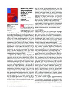
Fig. 1. Active-body not wheeled bending type modular snake robot. Coordinate frame assignments. Four of the 16 modules implemented are shown.
done on the locomotion of this kind of robots [3], [6]–[8]. Their locomotion capabilities makes these robots suitable for long distance deploy and recognizance of unstructured and unexplored terrains as the de-mining applications requires. Different gaits can be executed with the same robot. Some of these gaits have been researched pursuing the energy efficiency by our lab and will be presented on the next sections. Additionally some important features of this kind of robots can be exploited for de-mining applications. Including robot architecture (hardware and software), that simplifies the communications and control of the modules. The capacity of carrying multiple on-board mini-cameras and several types of sensors for perception fusion, and the energy management policies that allow a performance of the tasks and a large autonomy between charges. This paper is organized as follows: in section I, the locomotion schemes studied will be shown. Simulation examples
and results of them will also be presented. Some achievements of our work on robot architecture and control are treated on section II. In section III, The perception characteristics on which work have been done are explained. A discussion on the future integration of the previous developments, concluding remarks and future work will be shown on the last section.
the chain will roll without falling. Axis of the ellipse (“a” and “b”), determines the shape of the configuration and were used to modify locomotion parameters as velocity and acceleration. Metrics of efficiency were used on that model to examine the implementation of this gait on the future. B. Rolling on the outside of cylinders
I. L OCOMOTION The de-mining process as described, requires a deployable robot that once is threw, can acquire a configuration to recognize the terrain and ensure the visual inspection task. It will be expected that a retrieve mechanism exists in order to recuperate the robot from the scene in a safe manner. Taking into account that the modular snake robot is in fact a mobile robot, some of their locomotion capabilities can be exploited. Several gaits for modular snake robots have been explored as a research done in our lab in the last two years. The main objective has been focused on the search of a efficient gait. Closed relationships between gait parametrization and a concept of passive dynamic locomotion have been determined. In the following, our contributions regarding this topic will be reported. A. Rolling closed chain
Returning to the de-mining applications regarding this paper, a gait studied by our lab suited for an specific situation, is the rolling gait on the outside of a cylinder. Most of the environments where the explosive artifacts are placed, present a large amount of vegetation including bushes and trees. Tree branches offer a great camera location and a large coverage area because the robot can see from above (impossible for a human sight in that risk situation). That is why a modular robot gaits that uses cylinders, pipes or tree branches has been researched. We proposed a rolling gait as described on [6], [7]. Where the modular robot turns over itself around its longitudinal axis aided by a curve shape generated by the phase shift between the movements of their even and odd modules, which are twisted by 90◦ . This curve shape also give the robot mechanical stability within the horizontal surface where the modular robot is placed.
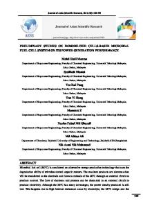
The first gait examined due to the work on modular snake robots in our lab, describes a modular chain 16-DOF that connects its first and end modules together, in order to achieve a closed chain shape. This research takes the concept from [8] and tries to determine a new dynamical model of the locomotion strategy used. A first contribution was done as reported in [9], where some preliminary aspects of the modeling and the structure of the robot were treated. The most recent work [10], proposes the robot as a ellipsoidal closed chain as seen on figure 2. Assuming no slip and no slide constraints, the closed kinematic chain is considered as an unstable system, as well as the inverted pendulum is. The fact that the chain will fall if it has an attack angle (i.e. the inclination of the major axis “a” of the ellipsoidal robot measured from the ground) is used in order to produce the motion. To avoid falling, motion starts, producing a linear acceleration and a linear velocity, so Fig. 3. Representation of the evolution, step by step of the gait in one rolling turn for a small radius.
Fig. 2.
Ellipsoidal closed shape configuration of the modular snake robot.
We investigate this gait for its relevance on the locomotion task that is intended to perform. Some modifications on the original rolling gait were done, including the fact that hanging around on the surface of a cylinder will demand that the modules without contact with the cylinder must remain turned off or in low consumption mode, for power saving. This is shown in the figure 3. We found that this gait presents vertical displacements of the Center of mass (marked as black crosses on the figure 3) during locomotion. This suggests a decrement in energy efficiency. A metric for this issue was determined as follows. If the kinetic energy used to displace vertically the total mass of the robot can be represented by the gravitational potential
energy needed to displace vertically the CM an amount of ∆xcm . This yields to the efficiency equation: η∆xcm =
v 2 − 2g∆xcm Ek − Ug = Ek v2
(1)
Notice that for low speeds (at specific pipe’s radius), the efficiency is low. As presented in [11], for a constant speed, as the radius decreases, the CM displacements increases. This will mean a decrease of the metric η∆xcm as well. So, in large radius pipes, the locomotion can be more effective than in thin ones. A stability analysis was also done. Figure 4 shows stable and unstable configurations.
configuration. Before the locomotion analysis, a macroscopic geometry analysis of the helix shape was developed. As in [12], we notice that a macroscopic geometry of the shape can determine the final joint space configuration of the robot. A set of parameters define the helix shape around a cylinder. The radius of the cylinder and the covered length were the main parameters that describe the shape. In the figure 5, two examples of an helix shape around a cylinder are shown.
Fig. 5. Representation of the helix rolling gait. Two different configurations.
Fig. 4.
Stability margin analysis. Stable and unstable configurations.
A special stability margin (SM) was designed for this kind of configurations. It can be applied for cylinder radius comparable with the robot length. It is presented here: dcm Cosβ (2) r Equation 2, dcm represents the distance vector (magnitude and sign) from the cylinder’s center to the position of the robot’s CM, r is the pipe’s radius, and β is the angle formed by the vector dcm with the direction of the gravity vector. In this specific case, due to the configuration and symmetry of the gait, this angle has a value of β = 0, ±180. If the position of the CM is the same as the center of the cylinder, SM = 0 and means that the robot is at the margin of being unstable. If SM > 0, the CM is below the center of the cylinder and the configuration is stable. A large SM, means that the configuration is more stable. Finally, if SM < 0 signifies a unstable configuration. A detailed explanation of this gait can be found in [11], including the simulations and experimental results done in our laboratory. SM = −
C. Helix shape to move on the outside cylinders Another pair of gaits currently examined in our lab, regarding locomotion on cylindric surfaces, present an helix shape
Using a simulation with a same module length 16-DOF robot, figure 5 shows blue and red shapes representing the robot in different helix configurations. The blue one, covers a larger length than the red one. However, the red one turns more times around the cylinder. Number of turns, is considered for stability purposes. In the same way, keeping constant the number of turns, a relationship between the cylinder radius and the length covered arises. If the radius increases, the length decreases. In this way and with a Frenet-Serret formulas and backbone curve parameterizations, the general shape can be determined and studied. With this shape, a pair of gaits have been studied, as said before. The first one, using the rolling motion as in [6] to achieve locomotion on horizontal test bed cylinders. A second one, explores the helix shape using a traveling wave from the first to the end modules and move the robot without lose stability. This gait is intended to be used for climbing. These pair of gaits are studied to refine an efficient and controlled method of locomotion for this kind of robots, with the aim to prove them on the field. D. Swing locomotion Another gait examined in our lab [13], uses the brachiation bio-inspired locomotion [14]. This is the gait used by primates to move from branch to branch on a tree. The analysis performed, tries to find a minimal-energy-initial-configuration of a 6-DOF planar modular robot, hanging from its end modules on a horizontal line to perform a swing movement. This movement allows the robot to use its built-in dynamics to convert the potential energy into kinetic energy as a pendulum, to generate displacements. This is a kind of passive dynamic locomotion scheme [15]. The objective of this gait, is to move from point a to point c, as in figure 6. The initial configuration hangs from o to
Fig. 6.
Swing locomotion gait. Robot configuration step by step.
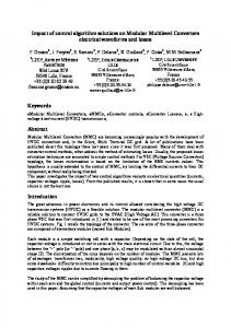
a, and is determined by a catenary curve [13]. This will guarantee minimum energy consumption. As motion starts, the chain will swing and the potential energy is transformed into kinetic energy as the end module passes the b point. After that, the energy will drive the end module to try to reach point c. An analysis was done regarding this energy conservation assumption. An energy efficiency analysis has been carried out, to determine what is the amount of energy needed for the robot to reach the goal. A motion planing study is proposed for this reason, as a future work. II. ROBOT ARCHITECTURE Accompanying the contributions on locomotion reported here, robot architecture becomes an important issue that demands a solid and scalable framework for its organization. A pair of contributions are developed regarding this area. The first one is concerned to the feedback control of the movements of the robot joints. The second one is a proposed research on multi-camera and sensor fusion. A. Distributed control In [16], results of the design of a model predictive control suited for a 6-DOF modular robot were reported. A model for 1-DOF module, is determined and validated. Several control strategies including GPC (generalized predictive control) and UMPC (unconstrained model predictive control) where evaluated. The controller was applied and distributed up to 6 modules and once again its whole performance was evaluated varying characteristics like prediction horizon, control horizon and the parameter weights. A disturbance rejection analysis also was done and in figure 7, an example of the performance of the different controllers changing the prediction horizon is shown. The distributed model predictive control was faster than a classical PID controller, robust to change of parameters like module length and inertia, ideal for implementation on different modular robots. The isolated controllers for each module increases the performance of the distributed controller and as a main objective, allows an easy implementation due to the modular nature of the robot architecture. Future work
Fig. 7. Position performance of the D-MPC with prediction horizon changes.
will be done on this area to increase the number of modules and to implement a digital controller of this type in a robot. B. Multi-camera and sensor fusion Sensor arrangements are commonly used in robotics. Our lab, has been proposed to work with camera arrangements to locate obstacles like in [17]. In the case of stereo vision applied to modular snake robot, only two cameras are used on the end of each module of the snake robot. However, it is now possible to place a camera in each module and redound total visual information acquired. Using platform sensors like accelerometers, gyroscopes and encoders is possible to find a common framework for the cameras located in each module. This is useful in remote operation, in the order that a single modular snake robot can inspect a larger area with different views. Nevertheless, more cameras mean more power consumption of the platform, and also increases the processing capabilities. If it is needed to process visual information, it is necessary to include an external processor. Our laboratory is currently working on this issue as a doctoral thesis, linking information from multiple cameras and doing the processing of this information in the cloud. The robot architecture comes crucial on this kind of applications for considerations regarding robot CPU and memory consumption and the management of computational resources in process, as like decision, communication, joint control, sensor feedback processing and of course locomotion. III. P ERCEPTION As said before, the de-mining application in which this kind of robots can be used, will be visual recognizance of potentially mined places. Two possibilities arises: an autonomous mine detection or a visual feedback to the base. Camera capability is an important characteristic that a robot like the proposed by our lab must have. Perception quality can be enhanced with a stereo camera arrange and sensor fusion. However, a recognizance configuration must be adopted by the robot and will be discussed.
of the pose. The first configuration on figure 9 is stable with static stability margin SSM = 0.73. As cameras move, the configuration changes, the SSM also changes in a range of 0.32 < SSM < 0.86, and the configuration remains stable. An example of the cameras movement can be seen in the second configuration on figure 9. 2) workspace: The end modules movement in the recognizance configuration must guarantee a complete semi spherical workspace coverage. A kinematic based analysis was done to
Fig. 8.
Recognizance configuration.
A. Recognizance configuration Computer vision algorithms implemented to perceive the scene, must require a camera auto-calibration procedure each time video or pictures are taken. Taking into account that, is desirable that a recognizance configuration is adopted by the robot to ensure a correct capture and minimize the time taken for the calibration. Even more, in the case of two cameras required for stereo vision. A stability issue regarding this configuration would be also important and will be described next. The figure 8 shows the recognizance configuration adopted by the robot. The first and end modules work as a pan and tilt turret for the cameras. Two needs arise: first, the stability of this pose must be analyzed to guarantee a successful capture. Second, the need of a functional workspace of the end modules for the motion of the cameras to ensure the spherical coverage of the perception algorithms. These will be described as follows. 1) Stability margins of recognizance configurations: Work has been done regarding the static stability of this configuration. In the figure 9, a spatial description of the configuration is shown. The center of mass (CM) position is calculated and a stability polygon is determined from the position of the modules in contact with the ground. A stability margin metric is used (defined as in [15]), to measure the stability
Fig. 10.
Workspace of the recognizance configuration.
determine the specifications of the dexterous workspaces of each pair of end modules. The results can be observed on figure 10. It is to notice that an intersection of the workspaces occurs. This spatial region can be considered for manipulation purposes for example, changing the end modules cameras for end effectors or grippers. B. Stereo vision In recognizance configuration, it is possible to place two cameras at each end of the modular snake robot, in order to generate a stereo vision arrangement. Many techniques applicable to this configuration already exist in the state of the art. Traditional theory of stereo, says that the cameras should be fixed with respect to each other, in order to calibrate stereo epipolar line to find and create a depth map due to disparity between image points. A solution to this problem, studied in our lab, is to use information from sensors on the chain to estimate the location of the cameras. Information can be improved by using Kalman filtering [18] on position values for each of the modules in the snake robot. An advantage of this method is that it has been widely used and requires only platform intrinsic parameters. Our lab also explore another solution. This one, uses techniques of dynamic stereo self-calibration, allowing to use information not only on the platform but in the camera parameters, movement of the cameras on the platform and the scene itself. These techniques do not require a stable position of the robot but are complex and this increases the processing time [19]. IV. C ONCLUSIONS AND F UTURE W ORK
Fig. 9. Projection of the center of mass and definition of the stability margin for the recognizance configuration.
Preliminary research on perception and locomotion has been developed over the last two years in our laboratory regarding
the use of modular snake robots for de-mining applications. The contributions reported on this document where already proved under laboratory conditions and simulations carried out. Towards a consolidation of a functional robotic platform for the mentioned tasks. The perception future work, looks for a consolidation of techniques, and algorithms to be implemented in a modular robot. It must satisfy requirements for stereo vision and on-board image processing capabilities. These requirements correspond to processing capabilities and also to a mechanical robustness intended to be put on the field. Sensor and multicamera fusion, as reported before, is a proposal for a doctoral research and will enhance the perception capabilities of the robot. The projection of the locomotion research in our lab, will be focused on two areas. The first one, pursuit the improvement of the robotic platforms. Two more robots are planned to be constructed. One that increases its joint torque and other that increases the joint angle speed. Test beds for these robots will be designed too, in order to increase the experimentation rigor. On the other hand, theoretical and simulation studies on locomotion will be developed as a doctoral research. Gait design techniques reported on [6], [7] simplified by the macroscopic geometry framework of [12], are a start point for this research. How to select an adequate gait to be executed by the robot, based on robot-ground interaction feedback and mechanical energy policies, are the main topics for this research. Efforts will continue on this area to increase the developments and achievements on modular snake robots for demining applications as reported on this paper. A consolidation of the results on the different areas of research must be integrated in order to build a prototype of a real robotic system, out of the laboratory and ready to be putted on a real field application. ACKNOWLEDGEMENTS We will thank all the students of the Pontificia Universidad Javeriana Master in electronics’s course “Robot design 20111”, specially to Carlos Giraldo, for their contributions on this paper. We also want to thank to the undergraduate final work students A. Trujillo, J. Igua, F. Cortes, D. Linares, and the Dr.D. Patino, for their help on this work. R EFERENCES [1] C. Parra, C. Otalora, A. Forero, and M. Devy, “Robot for nonconventional demining process: from remote control to autonomy,” in Using robots in hazardous environments: Landmine detection, de-mining and other applications. Woodhead Publishing Limited, 2011, pp. 32– 62. [2] S. Hirose, Biologically Inspired Robots: Snake-like Locomotors and Manipulators. Oxford University Press, 1993. [3] M. Yim, “New locomotion gaits,” in Robotics and Automation, 1994. Proceedings., 1994 IEEE International Conference on, May 1994, pp. 2508–2514 vol.3. [4] C. Wright, A. Johnson, A. Peck, Z. McCord, A. Naaktgeboren, P. Gianfortoni, M. Gonzalez-Rivero, R. Hatton, and H. Choset, “Design of a modular snake robot,” in Proc. IEEE International Conference on Intelligent Robots and Systems, IROS 2007, 2007.
[5] A. Transeth, R. Leine, C. Glocker, K. Pettersen, and P. Liljeback, “Snake robot obstacle-aided locomotion: Modeling, simulations, and experiments,” Robotics, IEEE Transactions on, vol. 24, no. 1, pp. 88– 104, 2008. [6] K. Lipkin, I. Brown, A. Peck, H. Choset et al., “Differentiable and piecewise differentiable gaits for snake robots,” in Proc. IEEE/RSJ International Conference on Intelligent Robots and Systems, IROS 2007, 2007. [7] M. Tesch, K. Lipkin, I. Brown, R. L. Hatton, A. Peck, J. Rembisz, and H. Choset, “Parameterized and scripted gaits for modular snake robots,” Advanced Robotics, vol. 23, no. 9, pp. 1131–1158, 2009. [8] J. Sastra, S. Chitta, and M. Yim, “Dynamic rolling for a modular loop robot,” Int. J. Rob. Res., vol. 28, pp. 758–773, June 2009. [Online]. Available: http://portal.acm.org/citation.cfm?id=1542017.1542023 [9] K. Melo and A. Velasco, “Motion analysis of a wheel-like articulated closed chain,” in ANDESCON, 2010 IEEE, 2010, pp. 1–6. [10] K. Melo, A. Velasco, and C. Parra, “Motion analysis of an ellipsoidal kinematic closed chain,” in Proc. IEEE IX Latin American Robotics Symposium and IEEE Colombian Conference on Automatic Control, Oct. 2011. [11] L. Paez, K. Melo, and C. Parra, “Center of mass displacements using rolling gaits for modular robots on the outside of pipes,” in Proc. IEEE IX Latin American Robotics Symposium and IEEE Colombian Conference on Automatic Control, Oct. 2011. [12] R. L. Hatton and H. Choset, “Generating gaits for snake robots: annealed chain fitting and keyframe wave extraction,” Auton. Robots, vol. 28, no. 3, pp. 271–281, 2010. [13] A. Trujillo, J. Igua, K. Melo, and C. Parra, “Din´amica pasiva para una cadena articulada coplanar de 6 dof,” in Proc. IEEE IX Latin American Robotics Symposium and IEEE Colombian Conference on Automatic Control, Oct. 2011. [14] H. Kajima, M. Doi, Y. Hasegawa, and T. Fukuda, “Energy based swing control of a brachiating robot,” in Proc. IEEE International Conference on Robotics and Automation. ICRA 2005, Apr. 2005. [15] I. Morazzani, D. Lahr, D. W. Hong, and P. Ren, “Novel tripedal mobile robot and considerations for gait planning strategies based on kinematics,” in Recent Progress in Robitics: Viable Robotic Service to Human. Springer-Verlag, 2008, pp. 35–48. [16] F. Cortes, D. Linares, D. Patino, and K. Melo, “A distributed model predicitve control (d-mpc) for modular robots in chain configuration,” in Proc. IEEE IX Latin American Robotics Symposium and IEEE Colombian Conference on Automatic Control, Oct. 2011. [17] M. Devy, M. Manzano, J. Boizard, P. Lacroix, W. Filali, and J. Fourniols, “Integrated subsystem for obstacle detection from a belt of microcameras,” in Advanced Robotics, 2009. ICAR 2009. International Conference on, june 2009, pp. 1–6. [18] P. Liang, Y. Chang, and S. Hackwood, “Adaptive self-calibration of vision-based robot systems,” Systems, Man and Cybernetics, IEEE Transactions on, vol. 19, no. 4, pp. 811–824, jul/aug 1989. [19] Y. Shen, D. Xu, M. Tan, and J. Yu, “Mixed visual control method for robots with self-calibrated stereo rig,” Instrumentation and Measurement, IEEE Transactions on, vol. 59, no. 2, pp. 470–479, feb. 2010.