membranes Article
Preparation and Characterization of TiO2/g-C3N4/PVDF Composite Membrane with Enhanced Physical Properties Huiya Wang 1, *, Ran Gong 1 and Xinliang Qian 2 1 2
*
School of Environmental Engineering, Nanjing Institute of Technology, Nanjing 211167, China;
[email protected] Jiangsu Huijin Environmental Protection Technology Co., Ltd., Wuxi 214241, China;
[email protected] Correspondence:
[email protected]; Tel.: +86-25-86118974; Fax: +86-25-86118974
Received: 11 January 2018; Accepted: 14 February 2018; Published: 5 March 2018
Abstract: TiO2 /g-C3 N4 /PVDF composite membranes were prepared by a phase inversion method. A comparison of the performance and morphology was carried out among pure PVDF, g-C3 N4 /PVDF, TiO2 /PVDF and TiO2 /g-C3 N4 /PVDF composite membranes. The results of permeability and instrumental analysis indicated that TiO2 and g-C3 N4 organic-inorganic composites obviously changed the performance and structure of the PVDF membranes. The porosity and water content of 0.75TiO2 /0.25g-C3 N4 /PVDF composite membranes were 97.3 and 188.3 L/(m2 ·h), respectively. The porosity and water content of the 0.75TiO2 /0.25g-C3 N4 membranes were increased by 20.8% and 27.4%, respectively, compared with that of pure PVDF membranes. This suggested that the combination of organic-inorganic composite with PVDF could remarkably improve UTS, membrane porosity and water content. Keywords: g-C3 N4 ; PVDF membrane; TiO2 ; characterization
1. Introduction The research on membranes has aroused great interest due to their wide applications in environmental protection, chemical purification, electrolytes, substrates, coatings, etc. [1–6]. Generally, there are two different types of membrane: inorganic and organic [7–10]. Poly (vinylidene fluoride) (PVDF), a common organic membrane material with excellent chemical resistance and thermal stability, has become a hot research topic in the membrane industry [11,12]. However, PVDF suffers from several disadvantages, such as low surface energy and strong hydrophobic properties, which largely limit the practical application of PVDF [13–16]. To date, a variety of strategies have been employed to fabricate hydrophilic PVDF membranes, including coating [17], adsorption [18], plasma treatment [19], blending [20] and surface grafting polymerization [21]. Among these, published research results thus far have been focused on PVDF membranes fabricated by nanoparticle coating, due to the unique electronic, magnetic and optical properties of nanoparticles, which would greatly improve the capabilities of polymers [22–25]. The nanoparticles introduced into PVDF membranes include polymeric chains and metal oxide. From among the polymeric chains, surface-modified macromolecules have been used as additives in the membrane matrix for anti-fouling applications [26–28]. This has been an effective strategy for enhancing anti-fouling properties by mitigating membrane fouling. Generally, coating a thin film and grafting polymer chains on the surface of the membrane have been two typical approaches in previous research [29]. Among metal oxide nanoparticles, TiO2 has received the most attention, due to its stability and availability [30–33].
Membranes 2018, 8, 14; doi:10.3390/membranes8010014
www.mdpi.com/journal/membranes
Membranes 2018, 8, 14
2 of 9
Recently, graphitic carbon nitride (g-C3 N4 ) has become a promising candidate for photocatalysis due to its low cost, visible-light response, simple synthesis and high chemical stability [34–37]. To date, there have been several reports on the synthesis and application of g-C3 N4 /PVDF membranes [38–40]. In our previous report, g-C3 N4 /PVDF membrane was fabricated through a phase inversion method. It has been found that dispersing g-C3 N4 into PVDF membrane can change the thermal decomposition process of PVDF membranes. In this paper, we propose a facial approach for obtaining TiO2 /g-C3 N4 /PVDF composite membranes by a phase inversion method. It is clearly demonstrated that the TiO2 and g-C3 N4 can obviously change the performance and structure of PVDF membranes. Moreover, the effects of organic-inorganic composites on the performance and structure of the PVDF membrane are also investigated. 2. Experiment 2.1. Materials Poly(vinylidenefluoride) (PVDF), the membrane material, was purchased from the Shanghai 3F New Materials Co., Ltd., Shanghai, China. N,N 0 -dimethylformamide (DMF), Silane coupling agent (SCA), polyethylene glycol (PEG 6000), Rutile TiO2 nanoparticles, and Melamine were purchased from Sinopharm chemical reagent Co., Ltd., Shanghai, China. All of the used chemicals were of analytical grade, and were used without further purification. 2.2. Preparation of Carbon Nitride (g-C3 N4 ) In a typical synthesis, 20 g melamine was transferred to an alumina crucible with a cover and heated to 550 ◦ C in Ar atmosphere for 2 h with a heating rate of 5 ◦ C/min. After undergoing various reactions at high temperature, a light-yellow powder of g-C3 N4 was finally obtained in the alumina crucible. 2.3. Preparation of Membrane In a typical synthesis p, 0.6 g PFG-6000 was introduced in 21 mL DMF and stirred for 30 min at 50 ◦ C. After that, 3 g PVDF and 1.5 mL SCA was added into the previous solution and stirred for another 30 min to form a homogenous suspension. The right amount of TiO2 and g-C3 N4 were added and stirred for 4 h. Finally, the final solution was slowly poured on the near end of the glass and a casting knife was placed on one edge of the glass to cast a membrane with a thickness of 2 mm. The obtained samples were denoted as xTiO2 /yg-C3 N4 /PVDF membrane, where x and y refer to the mass ratio of TiO2 and g-C3 N4 . 2.4. Contact Angle Measurement (Sessile-Drop Method) Water contact angle was measured with a Data Physics optical contact angle measuring instrument with the droplet size controlled using a Gilmont syringe (Chengde Dingsheng testing machine testing equipment Co., Ltd., Chengde, China). Distilled water was used for analysis. The advancing angle was measured when water was added to a droplet spreading over the membrane surface. Droplets were in placed in contact with the membrane at several different locations on each membrane sample to obtain a series of contact angle pairs. All measurements were carried out at room temperature. 2.5. Porosity Measurement In order to evaluate the porosity of the membranes, the membranes were placed in an air-circulating oven at 60 ◦ C for 24 h. Then, they were weighed after wiping off surface water with blotting paper.
Membranes 2018, 8, 14
3 of 9
After that, the wet membranes were placed in an oven at 80 ◦ C for 24 h in order to ensure they were completely dry. The porosity of the membranes (P) was calculated by: Membranes 2018, 8, x FOR PEER REVIEW
3 of 9
W0 − W1 P (%) = × 1000, Ah W0 W1 P(%) 1000 , where P is the porosity of membrane, W 0 is the wet Ahsample weight (g), W 1 is the dry sample weight (g), Awhere is the Psquare of membrane (cm2 ) and h the is the of membrane is the porosity of membrane, W0 is wetthickness sample weight (g), W1 is (mm). the dry sample weight (g), A is the square of membrane (cm2) and h is the thickness of membrane (mm).
2.6. Characterization
2.6. Characterization The mechanical strength of the membranes was tested by Instron 5542 Material Testing Instrument (Changchun Experimental Co., Ltd.,was Changchun, roomMaterial temperature (25 ◦ C) TheKexin mechanical strengthInstrument of the membranes tested byChina) Instronat5542 Testing Instrument Kexin Transform Experimental Instrument Co., Ltd., Changchun, China) aton room and 80% relative (Changchun humidity. Fourier Infrared (FT-IR) spectroscopy was performed a Nexus temperature (25 °C) and 80% relative humidity. Fourier Transform Infrared (FT-IR) spectroscopy 870 spectrometer (BRUKER, TENSOR27, Karlsruhe, Germany). Field Emission Scanning Electron was performed a Nexus 870 spectrometer Germany). Microscopy (S-4800 on Hitachi, Tokyo, Japan) was (BRUKER, applied toTENSOR27, observe theKarlsruhe, morphology of the Field resulting Emission Scanning Electron Microscopy (S-4800 Hitachi, Tokyo, Japan) was applied to observe the membranes. Each sample was clamped at the both ends with an initial gauge length of 100 mm and morphology of the resulting membranes. Each sample was clamped at the both ends with an initial width of 20 mm. Thermogravimetric Analysis (Simultaneous TGA-DSC, New Castle, DE, USA) was gauge length of 100 mm and width of 20 mm. Thermogravimetric Analysis (Simultaneous conducted under nitrogen from 30 to 700 ◦ C at a heating rate of 10 ◦ C·min−1 . X-ray diffraction patterns TGA-DSC, New Castle, DE, USA) was conducted under nitrogen from 30 to 700 °C at a heating rate were of recorded by−1X-ray (BRUKER-AXS, Karlsruhe, 10 °C·min . X-rayDiffractometer diffraction patterns were recorded by X-ray Germany). Diffractometer (BRUKER-AXS, Karlsruhe, Germany).
3. Results and Discussion
Transmittance (Arb.)
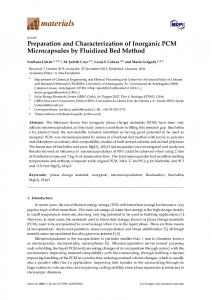
3. Results and Discussion Figure 1 depicts the FT-IR spectra of PVDF, TiO2 /PVDF, g-C3 N4 /PVDF and TiO2 /g-C3 N4 /PVDF Figure depicts the FT-IR spectra of PVDF, TiO2/PVDF, 3N4/PVDF and 2/g-C3IR N4/PVDF membranes. The1 0.75TiO membrane wasg-C characterized byTiO typical patterns of 2 /0.25g-C 3 N4 /PVDF membranes. The 0.75TiO 2 /0.25g-C 3 N 4 /PVDF membrane was characterized by typical IR patterns of PVDF membrane, indicating that the main chemical skeleton of PVDF membrane had been retained. − 1 PVDF membrane, indicating that the main chemical skeleton of PVDF membrane had been retained. There is a weak band located at 2917 cm , which is associated with the CH stretching of PVDF There[41]. is a The weak bandatlocated at−2917 cm−1, whichwith is associated with the CH stretching of PVDF 1 is associated structure band 3341 cm OH stretching vibration of water molecules structure [41]. The band at 3341 cm−1 is associated with OH stretching vibration of water molecules emanating from the polymer pores [42]. Notably, the absorption band of OH for TiO2 /PVDF was emanating from the polymer pores [42]. Notably, the absorption band of OH for TiO2/PVDF was weakened compared with that of PVDF, which may be caused by the effects of the hydrogen bonds weakened compared with that of PVDF, which may be caused by the effects of the hydrogen bonds between the the fluorine atoms andthe theoxygen oxygen atoms in 2,TiO 2 , implying between fluorine atomsininPVDF PVDF and atoms in TiO implying that thethat TiO2 the had TiO been2 had been successfully successfullydistributed distributed surface of PVDF. Interestingly, the band at cm 3341 cm−1 appeared −1 appeared onon thethe surface of PVDF. Interestingly, the band at 3341 in in g-C N /TiO /PVDF, which was associated with the stretching mode of N–H of g-C N g-C 3 3N 4 4/TiO22/PVDF, which was associated with the stretching mode of N–H of g-C3N4 [43]. This 3 4 [43]. phenomenon was attributed to thetog-C 3Ng-C 4 having beenalso successfully distributed on the surface of This phenomenon was attributed the having been successfully distributed on the 3 N4 also PVDF. surface of PVDF.
TiO2/g-C3N4/PVDF
TiO2/PVDF
PVDF
4000 3500 3000 2500 2000 1500 1000 -1
Wavelength (cm ) 1. spectra FTIR spectra of PVDF, 2/PVDF, g-C 3N4/PVDF 2/g-C 3N4/PVDF membranes. Figure Figure 1. FTIR of PVDF, TiOTiO g-C andTiO TiO membranes. 2 /PVDF, 3N 4 /PVDF and 2 /g-C 3 N4 /PVDF
Membranes 2018, 8, 14
4 of 9
Membranes 2018, 8, x FOR PEER REVIEW
4 of 9
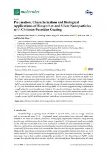
The morphologies of PVDF, TiO2 /PVDF, g-C3 N andand g-Cg-C 4 /PVDF 3 N43/TiO 2 /PVDF The morphologies of PVDF, TiO2/PVDF, g-C 3N4/PVDF N4/TiO 2/PVDF membranes membranes were investigated through SEM, and the results are presented in Figure 2. Before SEM, the sample membranes were investigated through SEM, and the results are presented in Figure 2. Before SEM, the sample to be dried. Generally, different drying methods been proposed to dry have membranes to be dried.have Generally, three differentthree drying methods have beenhave proposed to dry membranes, membranes, including room temperature-oven drying, ethanol-hexane and freeze-drying including room temperature-oven drying, ethanol-hexane drying, and drying, freeze-drying [44,45]. In this this paper, room temperature-oven drying is used. The at paper,[44,45]. room In temperature-oven drying is used. The membranes are membranes firstly driedare at firstly room dried temperature room temperature for 12 h, and then dried in an oven of 120 °C for 6 h. Compared with the porous ◦ for 12 h, and then dried in an oven of 120 C for 6 h. Compared with the porous and coarse structure and coarse structure of PVDF membrane (Figure 2a), both TiO2/PVDF and g-C3N4/PVDF (Figure of PVDF membrane (Figure 2a), both TiO2 /PVDF and g-C3 N4 /PVDF (Figure 2b,c) membranes show 2b,c) membranes show a smooth structure with circular and dark voids of uniform dimensions. a smooth structure with circular and dark voids of uniform dimensions. Notably, the g-C N4 /TiOand 2 /PVDF Notably, the g-C3N4/TiO2/PVDF membrane (Figure 2d) shows decreased but more 3regular membrane (Figure 2d) shows decreased but more regular and uniform voids. uniform voids. (a)
(b)
(c)
(d)
Figure 2. SEM images of (a) PVDF membrane; (b) TiO2/PVDF membrane; (c) g-C3N4/PVDF
Figure 2. SEM images of (a) PVDF membrane; (b) TiO2 /PVDF membrane; (c) g-C3 N4 /PVDF membrane; and (d) TiO2/g-C3N4/PVDF. membrane; and (d) TiO2 /g-C3 N4 /PVDF.
To further study the physical strength and durability of the membrane, the Ultimate Tensile Strength and theand results are shown Tables 1–3. expected, To further(UTS) studywas the measured, physical strength durability of the in membrane, theAs Ultimate Tensile 0.75TiO 2/0.25g-C3N4/PVDF membrane showed the highest UTS value. Values for TiO2/PVDF, Strength (UTS) was measured, and the results are shown in Tables 1–3. As expected, 0.75TiO2 / g-C3N4/PVDF, and 0.75TiO2/0.25g-C3N4/PVDF membranes were measured as 7.5, 7.1 and 8.7 MPa, 0.25g-C 3 N4 /PVDF membrane showed the highest UTS value. Values for TiO2 /PVDF, g-C3 N4 /PVDF, respectively. It is clear that the addition of TiO2 and g-C3N4 to PVDF improved the mechanical and 0.75TiO2 /0.25g-C3 N4 /PVDF membranes were measured as 7.5, 7.1 and 8.7 MPa, respectively. strength of the composite membranes. It is well known that membranes with macro-void It is clear that the often addition TiO2 and g-C3 Nproperties improved mechanical 4 to PVDF[42,46]. morphologies showof inferior mechanical It wasthe assumed that thestrength increasedof the composite membranes. It is well known that membranes with macro-void morphologies UTS in TiO2/g-C3N4/PVDF composite membrane was attributable to the decreased voids often in theshow inferior mechanical properties [42,46]. It was assumed that the increased UTS in TiO /g-C /PVDF membrane structure. Furthermore, 0.75TiO2/0.25g-C3N4/PVDF composite membrane exhibited 2 3 N4the composite was attributable tobe theattributable decreased to voids the membrane structure. Furthermore, highestmembrane tensile strength, which could thereinbeing fewer voids in the membrane structure. 0.75TiO /0.25g-C N /PVDF composite membrane exhibited the highest tensile strength, which could 2 3 4 To determine hydrophilicity/hydrophobicity of thestructure. membrane surface, the contact angle be attributable to therethe being fewer voids in the membrane wasdetermine measured.the As hydrophilicity/hydrophobicity shown in Table 1, the contact angleofofthe themembrane as-preparedsurface, membrane TiOangle 2 and To the with contact was g-C3N4 was decreased. It is well known that the membrane wettability of the membrane is measured. As shown in Table 1, the contact angle of the as-prepared membrane with TiO2 and g-C3 N4 influenced by the membrane material, as well as the surface porosity and roughness [47,48]. After was decreased. It is well known that the membrane wettability of the membrane is influenced by the adding TiO2 and g-C3N4, the surface porosity sharply increased. In other words, adding the TiO2 and membrane as well as theporosity surfaceand porosity and roughness [47,48]. TiO2 and g-C3N4 material, leads to a higher surface results in a decreased contact angleAfter of theadding membrane. g-C3 N4 , the surface porosity sharply increased. In other words, adding the TiO2 and g-C3 N4 leads to a higher surface porosity and results in a decreased contact angle of the membrane.
Membranes 2018, 8, 14
5 of 9
Table 1. TiO2 /g-C3 N4 /PVDF Membranes 2018, 8, x FOR PEER REVIEW
composite membranes compositions. 5 of 9
Membrane
Composition (wt %) UTS (MPa) Contact Angle Porosity Water Content Table 1. TiO composite membranes PVDF - 2/g-C3N4/PVDF 0.27 75.98 compositions. 50 90.3 TiO2 /PVDF 0.29 56.22 71 111.3 Membrane Composition (wt %) UTS (MPa) Contact Angle Porosity Water Content g-C3 N4 /PVDF 0.29 58.64 71 127.7 PVDF 0.27 75.98 50 90.3 TiO2 /g-C3 N4 /PVDF 0.75:0.25 0.33 62.57 67 143.2 TiO23/PVDF 56.22 111.3 TiO2 /g-C N4 /PVDF 0.5:0.50.290.29 70.89 60 71 124.5
g-C3N4/PVDF 0.29 58.64 71 TiO2/g-C3N4/PVDF 0.75:0.25 0.33 62.57 67 Table 2. Water content of TiO2 /g-C0.29 membrane. 3 N4 /PVDF composite TiO2/g-C3N4/PVDF 0.5:0.5 70.89 60 Contact Angle
Water Content
Initial 30 s StateContact Angle
Container 3 min Later Content Quality Water Quality
Table 2. Water content of TiO2/g-C3N4/PVDF composite membrane. Composition
Parametric Membrane
(wt %)
Parametric Membrane
PVDF TiO2 /PVDF PVDF g-C3 N4 /PVDF TiO2/PVDF TiO2 /g-C3 N4 /PVDF g-C3N4/PVDF TiO2 /g-C 3 N4 /PVDF TiO2/g-C3N4/PVDF TiO2/g-C3N4/PVDF
Composition (wt - %)
Initial 82.34 State 73.27 82.34 75.53 73.27 79.29 75.53 77.53 79.29 77.53
0.75:0.25 0.5:0.5
0.75:0.25 0.5:0.5
60 s
30 s 72.62
60 s 75.98
68.06 72.62 65.94 68.06 70.93 65.94 79.42
56.22 75.98 58.64 56.22 62.57 58.64 70.89
70.93 79.42
62.57 70.89
Container 1.9164 Quality 4.0196 1.9164 3.9521 4.0196 3.8871 3.9521 2.7236 3.8871 2.7236
3 min Later 7.7294 Quality 10.6646 7.7294 11.5824 10.6646 12.4376 11.5824 9.8236 12.4376 9.8236
127.7 143.2 124.5
JW L/ (m2 ·h) J W L/(m 90.3 2 ·h)
111.3 90.3 127.7 111.3 143.2 127.7 124.5 143.2 124.5
Table 3. Porosity of TiO2 /g-C3 N4 /PVDF composite membrane. Table 3. Porosity of TiO2/g-C3N4/PVDF composite membrane. Parametric Membrane
Parametric Membrane
Porosity (%)
Composition
%)%) Composition(wt (wt
PVDF
-
PVDF TiO2 /PVDF TiO2/PVDF g-C3 N4 /PVDF TiO2 /g-C3 N4 /PVDF g-C3N4/PVDF - 0.75:0.25 0.5:0.5 2 /g-C3 N4 /PVDF 0.75:0.25 TiO2/g-C3NTiO 4/PVDF TiO2/g-C3N4/PVDF 0.5:0.5
mwet (g)
m wet (g) 0.06 0.06 0.07 0.07 0.07 0.06 0.07 0.05 0.06 0.05
Porosity (%) ε m dry (g) 0.03 50% 0.03 0.02 71% 0.02 0.02 71% 0.02 0.02 67% 0.02 0.02 60% 0.02
mdry (g)
ε 50% 71% 71% 67% 60%
Weight %
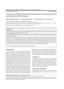
Membrane porosity and water content play an important role in membrane performance. and water contentcontent play anof important role in membrane performance. As As shown Membrane in Table 1,porosity the porosity and water the 0.75TiO 2 /0.25g-C3 N4 /PVDF composite shown in Table 1, the porosity and water content of the 0.75TiO2/0.25g-C3N4/PVDF composite 2 membranes were 97.3 and 188.3 L/(m ·h),2 respectively. This can be ascribed to the improvement in the membranes were 97.3 and 188.3 L/(m ·h), respectively. This can be ascribed to the improvement in hydrophilicity of the composite membranes because of the addition of TiO2 and g-C3 N4 . the hydrophilicity of the composite membranes because of the addition of TiO2 and g-C3N4. To further explore the pyrolysis properties of ofthethe0.75TiO composite 2 /0.25g-C 4 /PVDF To further explore the pyrolysis properties 0.75TiO 2/0.25g-C33 NN 4/PVDF composite membrane, a temperature-domain TGA was conducted, and the results are shown in membrane, a temperature-domain TGA was conducted, and the results are shown in Figure 3.Figure It is 3. It is clearly N4/PVDF composite membrane exhibited a higher thermal clearlyshown shownthat thatthe theTiO TiO 2/g-C33N composite membrane exhibited a higher thermal 2 /g-C 4 /PVDF decomposition temperature than that thepure purePVDF PVDF membrane, membrane, indicating thethe better thermal decomposition temperature than that of of the indicating better thermal stability the composite membrane, whichcould could potentially potentially be thethe physical andand stability of theofcomposite membrane, which be attributed attributedto to physical chemical interactions between PVDF chains and g-C 3N4 surface functional groups. chemical interactions between PVDF chains and g-C3 N4 surface functional groups.
TiO2/g-C3N4/PVDF PVDF
200
400
600
800
1000
Temperature Figure 3. TGA weight loss profiles of PVDF and TiO2/g-C3N4 PVDF. Figure 3. TGA weight loss profiles of PVDF and TiO2 /g-C3 N4 PVDF.
Membranes 2018, 8, 14
6 of 9
Membranes 2018, 8, x FOR PEER REVIEW
6 of 9
The crystal structures of the g-C3 N4 , PVDF and g-C3 N4 PVDF membranes were characterized by The crystal structures of the g-C3N4, PVDF and g-C3N4 PVDF membranes were characterized by ◦ ◦ XRD. AsAs shown ininFigure peaks around 13.0 observed XRD. shown Figure4,4,two two pronounced pronounced peaks at at around 13.0° and and 27.4°27.4 were were observed in the in the XRD patterns ofofg-C thein-plane in-plane structural packing and the interlayer 3N 44,, corresponding XRD patterns g-C 3N corresponding totothe structural packing motifmotif and the interlayer stacking of of aromatic [34].The TheXRD XRD patterns of the N /PVDF membrane stacking aromaticsystems, systems, respectively respectively [34]. patterns of the g-Cg-C 3N4/PVDF membrane 3 4 showed a weak peakofofg-C g-C33N N44,, which attributed to the low low g-C3N 4 content. showed a weak peak whichcould couldbebe attributed to the g-C N content. 3 4
Figure4.4.XRD XRD patterns patterns of 3N4, and g-C3N4/PVDF. Figure ofPVDF, PVDF,g-C g-C 3 N4 , and g-C3 N4 /PVDF.
4. Conclusions
4. Conclusions
A TiO2/g-C3N4/PVDF composite membrane was fabricated by a phase inversion method. A A TiO2 /g-C /PVDF composite membrane fabricated by pure a phase inversion method. 3 N4performance comparison of the and morphology was was carried out between PVDF membrane A comparison of the performance and morphology was carried out between pure PVDF membrane and PVDF composite membranes with different mass ratios of TiO2 and g-C3N4. It was clearly shown andthat PVDF membranes with ratios TiO2 and g-C the composite TiO2 and g-C 3N4 were able to different obviouslymass change the of performance and3 N structure PVDF shown 4 . It wasofclearly Contact measurements and SEM images that the addition 0.75 g TiO thatmembranes. the TiO2 and g-C3angle N4 were able to obviously changeshowed the performance and of structure of2 PVDF and 0.25 g g-C 3N4 to angle PVDF membrane greatly improved hydrophilicity to the membranes. Contact measurements and SEM images showeddue that thedecreased addition number of 0.75 g TiO2 voids. TheNporosity and water content of the 0.75TiO2/0.25g-C3N4/PVDF composite membranes andof0.25 g g-C 3 4 to PVDF membrane greatly improved hydrophilicity due to the decreased number were 97.3 and 188.3 L/(m2·h), respectively. The porosity and water content of the 0.75TiO2/0.25g-C3N4 of voids. The porosity and water content of the 0.75TiO2 /0.25g-C3 N4 /PVDF composite membranes membrane were increased by 20.8% and 27.4%, respectively, compared with those of the pure PVDF were 97.3 and 188.3 L/(m2 ·h), respectively. The porosity and water content of the 0.75TiO2 /0.25g-C3 N4 membrane. These results provide a novel way of improving membrane morphology, structure and membrane were increased bythe 20.8% and 27.4%, respectively, compared with those of the pure PVDF stability without influencing separation function.
membrane. These results provide a novel way of improving membrane morphology, structure and Acknowledgments: Financial support from the function. Nanjing Institute of Technology Innovation Fund Project. stability without influencing the separation Technical support from the Jiangsu Key Laboratory of Advanced Micro Nano Materials and Technology.
Acknowledgments: Financial support from the Nanjing Institute of Technology Innovation Fund Project. Author Contributions: Huiya Wang and Ran Gong conceived and designed the experiments; Xinliang Qian Technical support from the Jiangsu Key Laboratory of Advanced Micro Nano Materials and Technology. performed the experiments; Huiya Wang and Ran Gong analyzed the data; Xinliang Qian contributed
Author Contributions: Huiya Wang and Ranwrote Gongthe conceived and designed the experiments; Xinliang Qian reagents/materials/analysis tools; Huiya Wang paper. performed the experiments; Huiya Wang and Ran Gong analyzed the data; Xinliang Qian contributed Conflicts of Interest: The authors conflict of interest. reagents/materials/analysis tools; declare Huiya no Wang wrote the paper. Conflicts of Interest: The authors declare no conflict of interest. References 1.
Shu, C.; Song, B.; Wei, X.; Liu, Y.; Tan, Q.; Chong, S.; Chen, Y.; Yang, X.-D.; Yang, W.-H.; Liu, Y. Mesoporous 3D nitrogen-doped yolk-shelled carbon spheres for direct methanol fuel cells with polymer fiber Carbon 2018,Y.; 129, 613–620. 1. Shu, C.;membranes. Song, B.; Wei, X.; Liu, Tan, Q.; Chong, S.; Chen, Y.; Yang, X.-D.; Yang, W.-H.; Liu, Y. Mesoporous 2. 3D Colò, F.; Bella, F.; Nair, J.R.; carbon Gerbaldi, C. Light-cured polymer electrolytes for polymer safe, low-cost and nitrogen-doped yolk-shelled spheres for direct methanol fuel cells with fiber membranes. sustainable sodium-ion batteries. J. Power Sources 2017, 365, 293–302. Carbon 2018, 129, 613–620. [CrossRef] 3. Bella, F.; Pugliese, D.; Zolin, L.; Gerbaldi, C. Paper-based quasi-solid dye-sensitized solar cells. Electrochim. 2. Colò, F.; Bella, F.; Nair, J.R.; Gerbaldi, C. Light-cured polymer electrolytes for safe, low-cost and sustainable Acta 2017, 237, 87–93.
References
3.
sodium-ion batteries. J. Power Sources 2017, 365, 293–302. [CrossRef] Bella, F.; Pugliese, D.; Zolin, L.; Gerbaldi, C. Paper-based quasi-solid dye-sensitized solar cells. Electrochim. Acta 2017, 237, 87–93. [CrossRef]
Membranes 2018, 8, 14
4.
5. 6. 7.
8.
9.
10. 11. 12. 13.
14. 15. 16. 17.
18.
19.
20. 21.
22.
23.
24.
7 of 9
Hu, E.N.; Lin, C.X.; Liu, F.H.; Wang, X.Q.; Zhang, Q.G.; Zhu, A.M.; Liu, Q.L. Poly(arylene ether nitrile) anion exchange membranes with dense flexible ionic side chain for fuel cells. J. Membr. Sci. 2018, 550, 254–265. [CrossRef] Nair, J.R.; Bella, F.; Angulakshmi, N.; Stephan, A.M.; Gerbaldi, C. Nanocellulose-laden composite polymer electrolytes for high performing lithium–sulphur batteries. Energy Storage Mater. 2016, 3, 69–76. [CrossRef] Bella, F.; Ozzello, E.D.; Bianco, S.; Bongiovanni, R. Photo-polymerization of acrylic/methacrylic gel–polymer electrolyte membranes for dye-sensitized solar cells. Chem. Eng. J. 2013, 225, 873–879. [CrossRef] Jha, R.; Dulikravich, G.S.; Chakraborti, N.; Fan, M.; Schwartz, J.; Koch, C.C.; Colaco, M.J.; Poloni, C.; Egorov, I.N. Algorithms for design optimization of chemistry of hard magnetic alloys using experimental data. J. Alloys Compd. 2016, 682, 454–467. [CrossRef] Fan, M.; Liu, Y.; Jha, R.; Dulikravich, G.S.; Schwartz, J.; Koch, C.C. On the Formation and Evolution of Cu-Ni-Rich Bridges of Alnico Alloys with Thermomagnetic Treatment. IEEE Trans. Magn. 2016, 52, 1–10. [CrossRef] Wang, R.; Yang, C.; Fan, M.; Wu, M.; Wang, C.; Yu, X.; Zhu, J.; Zhang, J.; Li, G.; Huang, Q.; et al. Phase relationship of the TbO1.81 –Mn3 O4 –Fe2 O3 system synthesized at 1200 ◦ C. J. Alloys Compd. 2013, 554, 385–394. [CrossRef] Fan, M.; Liu, Y.; Jha, R.; Dulikravich, G.S.; Schwartz, J.; Koch, C.C. On the evolution of Cu-Ni-rich bridges of Alnico alloys with tempering. J. Magn. Magn. Mater. 2016, 420, 296–302. [CrossRef] Yeow, M.L.; Liu, Y.; Li, K. Preparation of porous PVDF hollow fibre membrane via a phase inversion method using lithium perchlorate (LiClO4) as an additive. J. Membr. Sci. 2005, 258, 16–22. [CrossRef] Yu, L.-Y.; Xu, Z.-L.; Shen, H.-M.; Yang, H. Preparation and characterization of PVDF–SiO2 composite hollow fiber UF membrane by sol–gel method. J. Membr. Sci. 2009, 337, 257–265. [CrossRef] Cha, S.; Kim, S.M.; Kim, H.; Ku, J.; Sohn, J.I.; Park, Y.J.; Song, B.G.; Jung, M.H.; Lee, E.K.; Choi, B.L.; et al. Porous PVDF as Effective Sonic Wave Driven Nanogenerators. Nano Lett. 2011, 11, 5142–5147. [CrossRef] [PubMed] Wu, C.M.; Chou, M.H. Polymorphism, piezoelectricity and sound absorption of electrospun PVDF membranes with and without carbon nanotubes. Compos. Sci. Technol. 2016, 127, 127–133. [CrossRef] Zaddach, A.J.; Niu, C.; Oni, A.A.; Fan, M.; LeBeau, J.M.; Irving, D.L.; Koch, C.C. Structure and magnetic properties of a multi-principal element Ni–Fe–Cr–Co–Zn–Mn alloy. Intermetallics 2016, 68, 107–112. [CrossRef] Zhang, G.; Fan, M. ChemInform Abstract: Synthesis and Magnetic Properties of Double B Mixed Perovskite Series La0.75 K0.25 Mn1−x FexO3 . ChemInform 2011, 42. [CrossRef] Sahoo, B.N.; Balasubramanian, K. Facile synthesis of nano cauliflower and nano broccoli like hierarchical superhydrophobic composite coating using PVDF/carbon soot particles via gelation technique. J. Colloid Interface Sci. 2014, 436, 111–121. [CrossRef] [PubMed] Dang, Z.-M.; Wang, H.-Y.; Zhang, Y.-H.; Qi, J.-Q. Morphology and Dielectric Property of Homogenous BaTiO3 /PVDF Nanocomposites Prepared via the Natural Adsorption Action of Nanosized BaTiO3 . Macromol. Rapid Commun. 2005, 26, 1185–1189. [CrossRef] Li, M.; Shi, J.; Chen, C.; Li, N.; Xu, Z.; Li, J.; Lv, H.; Qian, X.; Jiao, X. Optimized permeation and antifouling of PVDF hybrid ultrafiltration membranes: Synergistic effect of dispersion and migration for fluorinated graphene oxide. J. Nanopart. Res. 2017, 19, 114. [CrossRef] Liu, J.; Tian, C.; Xiong, J.; Wang, L. Polypyrrole blending modification for PVDF conductive membrane preparing and fouling mitigation. J. Colloid Interface Sci. 2017, 494, 124–129. [CrossRef] [PubMed] Shen, L.; Feng, S.; Li, J.; Chen, J.; Li, F.; Lin, H.; Yu, G. Surface modification of polyvinylidene fluoride (PVDF) membrane via radiation grafting: Novel mechanisms underlying the interesting enhanced membrane performance. Sci. Rep. UK 2017, 7, 2721. [CrossRef] [PubMed] Khayet, M.; Villaluenga, J.; Valentin, J.L.; Lopez-Manchado, M.; Mengual, J.I.; Seoane, B. Filled Poly(2,6-dimethyl-1,4-phenylene Oxide) Dense Membranes by Silica and Silane Modified Silica Nanoparticles: Characterization and Application in Pervaporation. Polymer 2005, 46, 9881–9891. [CrossRef] Liu, Z.; Pang, L.; Li, Q.; Zhang, S.; Li, J.; Tong, H.; Xu, Z.; Yi, C. Hydrophilic porous polyimide/β-cyclodextrin composite membranes with enhanced gas separation performance and low dielectric constant. High Perform. Polym. 2017. [CrossRef] Jia, H.; Wu, Z.; Liu, N. Effect of nano-ZnO with different particle size on the performance of PVDF composite membrane. Plast. Rubber Compos. 2017, 46, 1–7. [CrossRef]
Membranes 2018, 8, 14
25.
26. 27.
28. 29. 30. 31. 32. 33. 34.
35.
36.
37.
38. 39. 40. 41.
42.
43.
44. 45.
8 of 9
Albo, J.; Santos, E.; Neves, L.A.; Simeonov, S.P.; Afonso, C.A.M.; Crespo, J.G.; Irabien, A. Separation performance of CO2 through Supported Magnetic Ionic Liquid Membranes (SMILMs). Sep. Purif. Technol. 2012, 97, 26–33. [CrossRef] Rana, D.; Matsuura, T. Surface Modifications for Antifouling Membranes. Chem. Rev. 2010, 110, 2448–2471. [CrossRef] [PubMed] Manawi, Y.; Kochkodan, V.; Mahmoudi, E.; Johnson, D.J.; Mohammad, A.W.; Atieh, M.A. Characterization and Separation Performance of a Novel Polyethersulfone Membrane Blended with Acacia Gum. Sci. Rep. UK 2017, 7. [CrossRef] [PubMed] Rana, D.; Kim, Y.; Matsuura, T.; Arafat, H.A. Development of antifouling thin-film-composite membranes for seawater desalination. J. Membr. Sci. 2011, 367, 110–118. [CrossRef] Shahkaramipour, N.; Tran, T.; Ramanan, S.; Lin, H. Membranes with Surface-Enhanced Antifouling Properties for Water Purification. Membranes 2017, 7, 13. [CrossRef] [PubMed] Cao, X.; Ma, J.; Shi, X.; Ren, Z. Effect of TiO2 nanoparticle size on the performance of PVDF membrane. Appl. Surf. Sci. 2006, 253, 2003–2010. [CrossRef] Wang, X.; Xinxin Zhao, C.; Xu, G.; Chen, Z.-K.; Zhu, F. Degradation mechanisms in organic solar cells: Localized moisture encroachment and cathode reaction. Sol. Energy Mater. Sol. C 2012, 104, 1–6. [CrossRef] Chen, J.; Zhao, C.X.; Zhi, M.M.; Wang, K.; Deng, L.; Xu, G. Alkaline direct oxidation glucose fuel cell system using silver/nickel foams as electrodes. Electrochim. Acta 2012, 66, 133–138. [CrossRef] Deng, L.L.; Zhao, C.X.; Ma, Y.; Chen, S.S.; Xu, G. Low cost acetone sensors with selectivity over water vapor based on screen printed TiO2 nanoparticles. Anal. Methods 2013, 5, 3709–3713. [CrossRef] Cao, S.; Zhou, N.; Gao, F.; Chen, H.; Jiang, F. All-solid-state Z-scheme 3,4-dihydroxybenzaldehydefunctionalized Ga2 O3 /graphitic carbon nitride photocatalyst with aromatic rings as electron mediators for visible-light photocatalytic nitrogen fixation. Appl. Catal. B Environ. 2017, 218, 600–610. [CrossRef] Samanta, S.; Khilari, S.; Pradhan, D.; Srivastava, R. An Efficient, Visible Light Driven, Selective Oxidation of Aromatic Alcohols and Amines with O2 Using BiVO4 /g-C3 N4 Nanocomposite: A Systematic and Comprehensive Study toward the Development of a Photocatalytic Process. ACS Sustain. Chem. Eng. 2017, 5, 2562–2577. [CrossRef] Giannakopoulou, T.; Papailias, I.; Todorova, N.; Boukos, N.; Liu, Y.; Yu, J.; Trapalis, C. Tailoring the energy band gap and edges’ potentials of g-C3 N4 /TiO2 composite photocatalysts for NOx removal. Chem. Eng. J. 2017, 310, 571–580. [CrossRef] Zhao, C.X.; Wang, X.; Zeng, W.; Chen, Z.K.; Ong, B.S.; Wang, K.; Deng, L.; Xu, G. Organic photovoltaic power conversion efficiency improved by AC electric field alignment during fabrication. Appl. Phys. Lett. 2011, 99. [CrossRef] Wang, H.Y.; Hang, Z.S.; Lu, X.M.; Ying, S.J. Preparation and pyrolysis performance of g-C3 N4 /PVDF composite membrane. Mod. Chem. Ind. 2013, 33, 77–81. Yan, H.; Zhao, C.; Wang, K.; Deng, L.; Ma, M.; Xu, G. Negative dielectric constant manifested by static electricity. Appl. Phys. Lett. 2013, 102, 062904. [CrossRef] Zhao, C.X.; Mao, A.Y.; Xu, G. Junction capacitance and donor-acceptor interface of organic photovoltaics. Appl. Phys. Lett. 2014, 105. [CrossRef] Thomas, E.; Parvathy, C.; Balachandran, N.; Bhuvaneswari, S.; Vijayalakshmi, K.P.; George, B.K. PVDF-ionic liquid modified clay nanocomposites: Phase changes and shish-kebab structure. Polymer 2017, 115, 70–76. [CrossRef] Adams, F.V.; Nxumalo, E.N.; Krause, R.W.M.; Hoek, E.M.V.; Mamba, B.B. Preparation and characterization of polysulfone/β-cyclodextrin polyurethane composite nanofiltration membranes. J. Membr. Sci. 2012, 405–406, 291–299. [CrossRef] Yan, J.; Rodrigues, M.-T.F.; Song, Z.; Li, H.; Xu, H.; Liu, H.; Wu, J.; Xu, Y.; Song, Y.; Liu, Y.; et al. Reversible Formation of g-C3 N4 3D Hydrogels through Ionic Liquid Activation: Gelation Behavior and Room-Temperature Gas-Sensing Properties. Adv. Funct. Mater. 2017, 27. [CrossRef] Albo, J.; Wang, J.; Tsuru, T. Gas transport properties of interfacially polymerized polyamide composite membranes under different pre-treatments and temperatures. J. Membr. Sci. 2014, 449, 109–118. [CrossRef] Albo, J.; Hagiwara, H.; Yanagishita, H.; Ito, K.; Tsuru, T. Structural Characterization of Thin-Film Polyamide Reverse Osmosis Membranes. Ind. Eng. Chem. Res. 2014, 53, 1442–1451. [CrossRef]
Membranes 2018, 8, 14
46. 47.
48.
9 of 9
Ogawa, H.; Kanaya, T.; Nishida, K.; Matsuba, G. Phase separation and dewetting in polystyrene/poly(vinyl methyl ether) blend thin films in a wide thickness range. Polymer 2008, 49, 254–262. [CrossRef] Jiang, J.-H.; Zhu, L.-P.; Li, X.-L.; Xu, Y.-Y.; Zhu, B.-K. Surface modification of PE porous membranes based on the strong adhesion of polydopamine and covalent immobilization of heparin. J. Membr. Sci. 2010, 364, 194–202. [CrossRef] McCutcheon, J.R.; Elimelech, M. Influence of membrane support layer hydrophobicity on water flux in osmotically driven membrane processes. J. Membr. Sci. 2008, 318, 458–466. [CrossRef] © 2018 by the authors. Licensee MDPI, Basel, Switzerland. This article is an open access article distributed under the terms and conditions of the Creative Commons Attribution (CC BY) license (http://creativecommons.org/licenses/by/4.0/).