Principles and Protocols for Power Control in .... DESIGN PRINCIPLES FOR
POWER CONTROL ..... do this by modifying the sendto() system call, used to
send.
IEEE JOURNAL ON SELECTED AREAS IN COMMUNICATIONS: SPECIAL ISSUES ON WIRELESS AD HOC NETWORKS
1
Principles and Protocols for Power Control in Wireless Ad Hoc Networks Vikas Kawadia and P. R. Kumar Department of Electrical and Computer Engineering, and Coordinated Science Laboratory, University of Illinois at Urbana-Champaign, 1308 West Main St. Urbana, IL-61801. E-mail:{kawadia,prkumar}@uiuc.edu
Abstract— Transmit power control is a prototypical example of a cross-layer design problem. The transmit power level affects signal quality and thus impacts the physical layer, determines the neighboring nodes that can hear the packet and thus the network layer, affects interference which causes congestion and thus affects the transport layer. It is also key to several performance measures such as throughput, delay and energy consumption. The challenge is to determine where in the architecture the power control problem is to be situated, to determine the appropriate power level by studying its impact on several performance issues, to provide a solution which deals properly with the multiple effects of transmit power control, and finally to provide a software architecture for realizing the solution. We distill some basic principles on power control which inform the subsequent design process. We then detail the design of a sequence of increasingly complex protocols which address the multi-dimensional ramifications of the power control problem. Many of these protocols have been implemented, and may be the only implementations for power control in a real system. It is hoped that the approach in this paper may also be of use in other topical problems in cross-layer design.
I. I NTRODUCTION The power control problem in wireless ad hoc networks is that of choosing the transmit power for each packet in a distributed fashion at each node. The problem is complex since the choice of the power level fundamentally affects many aspects of the operation of the network: i) The transmit power level determines the quality of the signal received at the receiver. ii) It determines the range of a transmission. iii) It determines the magnitude of the interference it creates for the other receivers. Because of these factors: iv) Power control affects the physical layer (due to i). v) It affects the network layer since the transmission range affects routing (due to ii). vi) It affects the transport layer because interference causes congestion (due to iii). This material is based upon work partially supported by USARO under Contract Nos. DAAD19-00-1-0466 and DAAD19-01010-465, DARPA under Contract Nos. N00014-01-1-0576 and F33615-01-C-1905, AFOSR under Contract No. F49620-02-1-0217, DARPA/AFOSR under Contract No. F49620-02-1-0325, and NSF under Contract Nos. NSF ANI 02-21357 and CCR-0325716. Any opinions, findings, and conclusions or recommendations expressed in this publication are those of the authors and do not necessarily reflect the views of the above agencies.
vii)
viii)
ix) x)
xi)
xii)
xiii)
xiv)
xv)
Power control has a multi-dimensional effect on the performance of the whole system: The power levels determine the performance of medium access control since the contention for the medium depends on the number of other nodes within range. The choices of power levels affect the connectivity of the network (see [1], [2]), and consequently the ability to deliver a packet to its destination. The power level affects the throughput capacity of the network [3]. Power control affects the contention for the medium, as well as the number of hops, and thus the end-to-end delay. Transmit power also affects the important metric of energy consumption. In addition, the assumption of fixed power levels is so ingrained into the design of many protocols in the OSI stack that changing the power levels results in their malfunctioning. Changing power levels can create uni-directional links, which can happen when a node i’s power level is high enough for a node j to hear it, but not vice-versa. Bi-directionality of links is implicitly assumed in many routing protocols. For example, Distributed BellmanFord, the basis of many minimum hop routing protocols, uses the dynamic programming recursion: Vij = min[cik + Vkj ], where cik =1 if k is is a neighbor of i k and ∞ otherwise, and Vij is the minimum number of hops from i to j. If i can hear k, then node i may hear the distance Vkj advertised by node k, but 1+Vkj is not the distance from i to j via k, if k cannot hear i. The problem is that the notion of a “neighbor” ceases to be a symmetric notion and cik 6= cki . Medium access protocols such as IEEE 802.11 [4] implicitly rely on bi-directionality assumptions. For example, a CTS from j silences only those nodes which can hear j, but there may be other higher powered nodes that j can hear. ACKS also assume bi-directional links. Various protocols employ route reversals, e.g., RouteReply packets in AODV [5] and DSR [6] reverse the route followed by the Route Request packets.
IEEE JOURNAL ON SELECTED AREAS IN COMMUNICATIONS: SPECIAL ISSUES ON WIRELESS AD HOC NETWORKS
Transmit power control is therefore a prototypical crosslayer design problem affecting all layers of the protocol stack from physical to transport, and affecting several key performance measures, including the trinity of throughput, delay and energy consumption. Cross-layer design, in general, should be approached holistically with some caution, keeping in mind longer term architectural issues [7]. Thus arises the question of where in the network architecture should power control be located, the resolution of which requires an appreciation of the issues involved at each layer. The precise choice of the power level itself needs to be guided by its impact on multiple performance measures which requires a theoretical understanding of the impact of power control. Finally, there arises the issue of software architecture. We need to take into account the software organization of the IP stack and the interplay between the kernel, user-space applications and the firmware on the wireless cards. The solution also needs to be appropriately modularized to allow future changes in routing protocols without redesigning the entire power control solution. Given this complex web of interactions, we begin by distilling a few basic design principles to guide our design process for power control. Then we propose some protocols which attempt to achieve several design objectives and perform several optimizations simultaneously. The COMPOW protocol [8] attempts to increase network capacity, while meeting the needs of several other layers by choosing a common power level throughput the network. The CLUSTERPOW protocol [9] relaxes this constraint and provides a joint solution to the power control, clustering and routing problem, again with the goal of maximizing network capacity. The Tunnelled CLUSTERPOW protocol develops a more sophisticated way of achieving a finer optimization for network capacity, at the cost of greater implementation complexity. The MINPOW protocol achieves a globally optimal energy consumption solution for awake nodes, but may or may not increase network capacity depending on the wireless hardware. The LOADPOW protocol attempts to reduce end-to-end delay by using higher power levels, when the network load is low. We also present software architectural designs for cleanly implementing these protocols. We have implemented COMPOW, CLUSTERPOW and MINPOW. Tunnelled CLUSTERPOW requiring considerably more implementation effort was not implemented, while LOADPOW could not be implemented as it needs changes in the MAC protocol which resides in the firmware of the wireless card, which is not accessible. Experimental performance evaluations were anyway not possible for any of the protocols due to hardware limitations, which is essentially designed for changing power levels at startup. Thus, for quantitative comparisons we have also implemented some of these protocols in the NS2 simulator, which interestingly turned out to require more effort than the real implementations in the kernel. II. D ESIGN P RINCIPLES FOR P OWER C ONTROL We begin our exploration by presenting some design principles for power control.
2
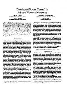
I. To increase network capacity it is optimal to reduce the transmit power level. Any transmission causes interference in the surrounding region due to the shared nature of the wireless channel. The area of this interference is reduced by reducing the transmission range, or the power level. Low power levels, however, result in a larger number of shorter hops, thus increasing the relaying burden on a node. For a transmission range of r, the area of the interference is proportional to r2 , whereas the relaying burden, i.e., the number of hops, is inversely proportional to r. The area consumed by a packet is thus proportional to r (r 2 for 3-D networks), implying that reducing the transmit power level increases network capacity; see [8], [3]. II. Reducing the transmit power level reduces the average contention at the MAC layer. For any point in the domain, there are an average of cr 2 transmitters within range, where c is the spatial density of nodes. The traffic flowing through each node is proportional to 1r , the relaying burden imposed on the nodes. Thus the net radio traffic in contention range is proportional to r, again minimized when r is small [8]. III. The impact of power control on total energy consumption depends on the energy consumption pattern of the hardware. Power consumption for communication has three components: PRxelec , the power consumed in the receiver electronics for processing, PT xelec , the power consumed by the transmitter electronics for processing, and PT xRad (p), the power consumed by the power amplifier to transmit a packet at the power level p, where p is the actual power that is radiated in the medium. Also define PIdle to be the power consumed when the radio is on but no signal is being received, and finally let PSleep be the power consumed when the radio is turned off. Based on the relative values of these parameters, we can distill the following three principles regarding energy consumption: A) If the energy consumed for transmission, PT xRad (p), dominates, then using low power levels is broadly commensurate with energy-efficient routing for commonly used inverse αth law path loss models, with α ≥ 2. The energy required to communicate with a node at a distance r increases as r α where α ≥ 2, and if this is the dominant mode of energy P consumption, energy efficient routing seeks to minimize i riα , where ri is the range of the ith hop. It can be shown [8] that for every α ≥ 2, the graph consisting of edges lying along some power optimal route between any pair of nodes can be chosen to be planar with straight line edges between nodes. Figure 1 shows all such paths, in a topology of randomly placed nodes. In such a planar graph connections are only with nearby nodes or else they would intersect other edges. Thus, using low transmit power levels is broadly commensurate with energy efficient routing. B) When PSleep is much less than PIdle , then turning the radio off whenever possible becomes an important energy saving strategy. This is the case for many commercial-offthe shelf wireless cards. Some estimates in [10], [11] list PIdle to be about 20 times PSleep for current hardware. “Power management” protocols [12], [13], [14], which seek to put nodes to sleep, while maintaining network connectivity and buffering packets for nodes that are “sleeping”, become important. However, in this work we do not address the
IEEE JOURNAL ON SELECTED AREAS IN COMMUNICATIONS: SPECIAL ISSUES ON WIRELESS AD HOC NETWORKS
3
p3 > p2 > p1
10000
p3 8000
Delay
Y distance in meters
p2 6000
p1
4000
2000
Network throughput 0
0
2000
4000
6000
8000
10000
X distance in meters
Fig. 1.
Fig. 2. A qualitative sketch of the expected delay-throughput curves at different power levels.
The graph of links lying along power-optimal routes. Delay -- Throughput; 80 nodes, 1-14 CBR conns 180
To satisfy network connectivity one may need a range even greater than this. IV. When the traffic load in the network is high, a lower power level gives lower end-to-end delay, while under low load a higher power gives lower delay. At every hop a packet experiences: processing delay, propagation delay and queuing delay. Processing delay includes the time taken by the radio to receive the packet, decode it and retransmit it if necessary. Propagation delay is the time taken by the radio waves to travel the physical distance separating the nodes. Queuing delay is the time spent by the packets waiting in the queue of the forwarding nodes because the medium is busy. The end-toend delay for a packet is the sum of the delays it experiences at every hop. Processing delay grows approximately linearly in the number of hops and is thus inversely proportional to the range. Queuing delay depends on the accessibility of the medium, i.e., on the MAC contention and the interference in the neighborhood. Since contention increases linearly with the range, queuing delay increases super-linearly with the power level, given the convex dependence of delay on load. Power control does not affect the propagation delay much, as it depends only on the end-to-end distance. Thus a higher transmit power implies higher queuing delay, whereas a lower transmit power implies higher processing delay. Whether the processing delay dominates or the queuing delay dominates, depends on the network load. Under low load, queuing delay is insignificant, and thus it is beneficial to use a higher transmit
power 6 power 5 power 4 power 3
160 End2end delay in msecs
sleeping nodes, but only the awake nodes. Power management schemes can possibly be integrated with our power control schemes to run in unison. C) When a common power level is used throughout the network, then there exists a critical transmission range rcrit , below which transmissions are sub-optimal with regards to energy consumption. The energy consumed for transmitting a packet, using hops of power level r, from a source to a destination separated by distance d, is given by dr (PRxelec + PT xelec + cr α ), which is minimized at s PRxelec + PT xelec (1) rcrit = α c(α − 1)
140 120 100 80 60 40 20 0 50
100
150 200 250 Aggregate Thruput in Kbits/sec
300
Fig. 3. Delay-throughput curves at different power levels obtained through simulations.
power which reduces the processing delay. On the other hand, when the network load is high, queuing delay dominates, and it is desirable to use a low transmit power to reduce the total end-to-end delay. This is qualitatively indicated in Figure 2. An ideal power control protocol should follow the troughs of these curves. To verify our predictions and to get an estimate of the cross-over points, we simulated a topology of 80 nodes placed randomly in a 1000×500m rectangular grid, using the NS2 simulator. The MAC protocol used was IEEE 802.11b and the routing protocol was DSDV. The network load was varied by increasing the number of randomly selected source-destination pairs which carried constant bit rate UDP traffic. As seen in Figure 3, a lower power level can sustain more traffic since it blows up later than a higher power level curve. However at low loads, a higher power level gives a lower delay. The delay jitter also shows a similar trend. V. Power control can be regarded as a network layer problem. This is a central thesis of our approach to power control. Power control impacts multiple layers of the network stack, including the physical, the data link, and the network layers. Numerous approaches (e.g., [15], [16]) attempt to solve the power control problem at the MAC layer. The strategy is to adjust the transmit power level of every packet such that the SINR at the intended receiver is just enough for decoding the packet. The claim is that this minimizes interference as well
IEEE JOURNAL ON SELECTED AREAS IN COMMUNICATIONS: SPECIAL ISSUES ON WIRELESS AD HOC NETWORKS
III. T HE COMPOW P OWER C ONTROL P ROTOCOL A first cut simple solution for power control is the COMPOW protocol [8]. In COMPOW, the goal of the optimization for each node is to choose a) a common power level b) set this power level to the lowest value which keeps the network connected, and c) keeps the energy consumption close to minimum. A common power throughout the network for all the packets has the key property of ensuring bi-directionality of links due to reciprocity of electromagnetic waves in space, assuming that other factors such as interference are relatively homogeneous. Bi-directionality ensures that the MAC and network layers work properly and also enables use of the standard OSI protocols like ARP, DHCP, etc. We ensure that using too low a power level does not increase the energy consumption by restricting the lowest admissible power level to the one corresponding to rcrit , in line with the argumentation in Section II, point IIC). The setting of the lowest common power level is designed to maximize network capacity. In fact, under a homogeneous spatial distribution, it is shown in [3] that choosing a common power level can decrease capacity at most by a factor of √ log n, where n is the number of nodes, in comparison to allowing the flexibility of a different power level for each packet at each node. The next issue is to show how this common power level is to be realized at the network level. The architectural solution consists of running multiple independent proactive routing protocols, one at each admissible power level, and a COMPOW agent figures out the lowest common power for connectivity using these routing tables. This is similar to the architecture shown in Figure 5. Various optimizations are further possible. COMPOW has certain appealing features: i) Provides bidirectional links, assuming homogeneous interference.
100 mW
S
N1 r
luste
Wc
10 m
100
mW
N2 ster
W
1m
clu
10
mW
N3 D
1 mW
as saves energy. One point to note though is that the intended receiver is determined by the network layer, i.e., by the routing table entry, and not by the MAC layer. The job of the MAC layer is only to transmit the packet to the receiver specified by the higher layers. Thus, placing power control at the MAC layer does not give the routing protocol the opportunity to determine the optimal next hop or the intended receiver. In other words, the MAC approach to power control only does a local optimization whereas network layer power control is capable of a global optimization. When the power level used by a node changes slowly compared to routing updates, power control can be viewed as the “topology control” problem. A more tight coupling of routing and power control can be effected by per-packet power control, which enables us to solve the clustering problem also in a clean way along with the power control problem, as we will see in the sequel. Thus we argue for power control to be properly situated as a network layer protocol. The above is only a guiding principle. In order to solve the power control problem, we need to show how it can be solved at the network layer resolving all the issues that we have raised. Some solutions may need help from other layers and one may resort to cross-layer design.
4
Fig. 4. Routing by CLUSTERPOW in a typical non-homogeneous network.
ii) Allows each layer to function properly. iii) Is theoretically well supported in terms of its design objective of choosing the lowest common power level subject to connectivity. iv) Has a modular implementation at the network layer. IV. T HE CLUSTERPOW P OWER C ONTROL P ROTOCOL COMPOW works well if nodes are distributed homogeneously in space, but even a single outlying node could cause every node to use a high power level. So when the spatial distribution of nodes is inhomogeneous, it is obviously not optimal to use a common power level throughout the network. We might allow nodes to use a power level which depends on the destination of the packet. This suggests a simple algorithm for routing and power control in clustered networks, which attempts to maximize spatial reuse and hence network capacity. Every node forwards a packet for a destination d using the smallest power level p such that the destination d is reachable, possibly in multiple hops, using only p. In some sense this is a greedy algorithm, since every node uses the lowest power level which guarantees reaching the destination according to the information it has. This is executed at the source and every intermediate node. The consequence is that if a node further downstream knows how to reach the destination using a lower power level, then it uses that lower power level for forwarding the packet. Figure 4 illustrates the routes chosen, and the power level used when the above algorithm, called CLUSTERPOW [9], is executed on a typical clustered network . A. CLUSTERPOW Architecture and Implementation To implement CLUSTERPOW, each node runs a routing protocol at each power level pi , thereby independently building a routing table RTpi by exchanging hello messages at only that power level. To forward a packet for a destination d, a node consults the lowest power routing table in which d is present, say RTpmin , and forwards the packet at power level pmin to the next hop indicated in the routing table RTpmin . The software architectural design of the CLUSTERPOW protocol is similar to that of COMPOW, and is illustrated in Figure 5. Each node runs multiple routing daemons, one for each power level in user-space, and the routing tables constructed are made available to the CLUSTERPOW agent.
IEEE JOURNAL ON SELECTED AREAS IN COMMUNICATIONS: SPECIAL ISSUES ON WIRELESS AD HOC NETWORKS
5
APPLICATIONS (DATA)
CLUSTERPOW AGENT
X Y
RDPmin
...
RDPx
RDPy
RD Pz
...
RDPmax
S
Path P
D
user space kernel space
Port demultiplexing
TRANSPORT LAYER Dest Nexthop Metric Txpower
NETWORK LAYER
DATA LINK + MAC PHYSICAL
CHANNEL
Fig. 5.
Architectural design of CLUSTERPOW.
The agent then populates the entries in the kernel routing table, which is the one actually consulted for forwarding packets. Each entry in the kernel routing table lists not only the nexthop for that destination, but also the power level that is to be used for transmission to the next-hop. The architectural design as presented above capitalizes on certain assumptions about the wireless hardware. The first assumption is that transmission is possible at a small number of discrete power levels, so that we can run a routing daemon at each power level. This is true of the current off-the-shelf wireless network interface cards capable of transmit power control. For example, the Cisco Aironet 350 series cards (IEEE 802.11b compliant) allow the transmit power level to be set to one of 1, 5, 20, 30, 50 and 100 mW. The second assumption is that the cards are capable of per-packet power control without much latency. This is of course a pre-requisite for any dynamic power control scheme. Unfortunately, this is not entirely true for the Cisco 350 cards that we have used. Even though we could modify the driver to enable per-packet power control, the switching latency is inexplicably as high as 100ms, when measured at the network layer. We believe that this is a firmware limitation, rather than a fundamental limitation of the electronics, since fast power control is quite common in, e.g., CDMA networks. Since the firmware on the cards is proprietary we do not have access to it, but we envision that user-demand may lead to the problem being fixed in future.
Fig. 6. Suppose there is a loop on the path P from S to D. Dashed lines indicate paths consisting of many hops.
network is respected in the way routes are chosen. The hierarchy of clustering could be as deep as the number of power levels. Clustering is also dynamic and distributed, because it is integrated with a routing protocol that has these properties. ii) CLUSTERPOW can be used with any routing protocol, reactive or proactive. In the case of a proactive routing protocol (e.g., DSDV [17]), all the routing tables at different power levels are maintained through hello packets and the kernel routing table is composed from them. For a reactive or on-demand routing protocol like AODV [5], route discovery requests can be sent out at all the power levels available. The lowest power level which results in a successful route discovery can then be used for routing the packet. iii) CLUSTERPOW is loop free. The kernel routing table in CLUSTERPOW is a composite of the individual routing tables at different power levels. It is possible that this interaction between routing protocols could lead to packets getting into infinite loops However this is not the case, as we prove below. Theorem 1: The CLUSTERPOW power control protocol provides loop free routes. Proof: The proof is based on the key property of CLUSTERPOW, that it chooses routes such that subsequent hops use a sequence of non-increasing power levels. This is because, when a particular power level p is used, the destination is present in the routing table corresponding to p, and there is guaranteed to exist a path of power level at most p from the current node to the destination. Thus, further downstream, the power can only decrease. Thus, if there is a loop as shown in Fig. 6, i.e., a packet on its way from node S to node D follows the path S-X-Y-X. . . , then all the hops on the loop have to be of the same power level. But that cannot happen since the underlying routing protocol is loop free. C. CLUSTERPOW Implementation and Software Architecture
B. Properties of CLUSTERPOW i) CLUSTERPOW provides implicit, adaptive, and distributed clustering based on transmit power. Clustering based on geographical location could be problematic since GPS, for example, may not work indoors. However, an even more serious problem is that geographical proximity does not guarantee radio proximity, since there may be a radio-opaque obstacle between two nearby nodes. In contrast, in CLUSTERPOW, clustering is implicit and does not require any cluster-head or gateway nodes. The clusters are determined by reachability at a given power level and the clustered structure of the
CLUSTERPOW has been implemented in Linux. The software architecture is illustrated in Figure 7. Running multiple routing daemons, one at each power level, is achieved by assigning a pre-decided port to each power level and binding the corresponding routing daemon to that port. The CLUSTERPOW agent communicates with these routing daemons using an an inter-process communication mechanism. Next we need to introduce “transmit power” as one of the properties of the packet. This is done by adding a field txpower to the skb data structure in the Linux kernel, which stores all the information about a packet, and is passed between various layers. The network layer sets skb→txpower by consulting
IEEE JOURNAL ON SELECTED AREAS IN COMMUNICATIONS: SPECIAL ISSUES ON WIRELESS AD HOC NETWORKS
CLUSTERPOW AGENT
6
APPLICATIONS (DATA) 100 mW
S 1m
W
RDPmin
...
RDPx
RDPy
RD Pz
...
r
N2
set skb−>txpower for DATA packets
W
1m
clu
mW
N3 D
1 mW
NETWORK LAYER
10
ster
kernel space
/proc
mW
luste
Wc
10 m set skb−>txpower for broadcast packets
100
RDPmax
user space
TRANSPORT LAYER
N1
10 mW
N0
POWEROUTE MODULE Dest Nexthop Metric Txpower
DEVICE DRIVER
change_power() (for every packet)
Fig. 8. Modifying the CLUSTERPOW protocol, so that the 100 mW hop from S to N1 can be replaced by two hops of 1 mW and 10 mW each.
S
NETWORK CARD
N1 Fig. 7.
10 mW
N10
10 mW
D
The software architecture of CLUSTERPOW.
the extended kernel IP routing table, which now also has a field called txpower for each entry. This extension of the kernel routing table is cleanly achieved by storing the extra information in a custom kernel module (poweroute), which uses the Netfilter packet filtering facility to trap packets after they have consulted the IP routing table and set the skb→txpower field appropriately. The information stored by the poweroute module is updated by the CLUSTERPOW agent through the /proc interface. Broadcast packets, however, do not consult the routing table. The power levels for these packets have to be specified by the application generating them, e.g., the various routing daemons. We provide a mechanism to do this by modifying the sendto() system call, used to send UDP packets. Finally, the network driver for the Cisco 350 cards was modified so that it reads the power level from skb→txpower and sets it on the card before sending a packet. The implementation described above is architecturally clean and modular. It makes minimum intrusions into the kernel; most of them being concerned with making the kernel aware of the concept of a per-packet transmit power. The implementation is fairly generic and could be used for other power control protocols. COMPOW and MINPOW (described later) use the same architecture. Source code is currently available on-line at http://decision.csl.uiuc.edu/∼kawadia/adhoc.html V. R ECURSIVE L OOKUP S CHEMES While CLUSTERPOW attempts to maximize spatial reuse, it does not achieve optimality in that regard. We can do better as demonstrated in Figure 8, where the earlier 100 mW hop from node S to node N1 is now replaced by shorter hops. A possible scheme to achieve the routing shown in Figure 8 is recursive lookup of routing tables. In this scheme the next hop is recursively looked up in successively lower power level routing tables, until we get to the lowest power level routing table at which the next hop is reachable. Thus, in Figure 8, the next hop N1 at node S is looked up in lower power routing tables to find that it is reachable at 10 mW through N0, which in turn is reachable at 1 mW. So ultimately the packet is given to N0 at 1 mW.
1 mW Fig. 9.
The recursive lookup scheme is not free of infinite loops.
This recursive lookup scheme seems to have achieved a finer optimization with regard to network capacity, but it does not guarantee freedom from loops, i.e., packets can keep coming back to a node indefinitely. The network in Fig. 9 provides a counterexample. Node S needs to send a packet to node D. It determines that the next hop is node N10 in the 10 mW routing table. Recursive lookup for N10 reveals that it is reachable at 1 mW, with next hop is N1. Thus S forwards the packet to N1 at 1 mW. After the packet reaches N1, it runs the same algorithm. It finds that the lowest power level at which D is reachable is 10 mW and that the next hop is S. Since S itself is reachable at 1 mW, the packet is handed over back to node S, and we have an infinite loop. A. The Tunnelled CLUSTERPOW Protocol To ensure that the packets in the recursive lookup scheme do reach their destination, we need to ensure that they make progress towards the destination. One way to achieve is this is to tunnel the packet to the next-hop using hops of lower power level, instead of sending it directly. Tunnelling can be viewed as a way of introducing some state or memory in the packet, and can be achieved by IP in IP encapsulation. While doing a recursive lookup for the next-hop, we also recursively encapsulate the packet with the address of the node for which the recursive lookup is being done. The decapsulation is also done recursively when the packet reaches the corresponding next hop. This gives rise to the Tunnelled CLUSTERPOW protocol. As shown in Fig. 10, this does resolve the loop in the example of Fig. 9. Now when node S forwards the packet to N1, it encapsulates the packet with the address of N10. Thus N1 does a routing lookup, not for the destination D, but for node N10. It finds that N10 is reachable at 1 mW through the path N2, N3 . . . , and it forwards the packet to N2 at 1
IEEE JOURNAL ON SELECTED AREAS IN COMMUNICATIONS: SPECIAL ISSUES ON WIRELESS AD HOC NETWORKS
N10 D DATA
7
APPLICATIONS (DATA)
D DATA MINPOW DAEMON
S
N10
10 mW
D
Hel
lo p
ets
ax
W
pow
er l
kernel space
eve
l
TRANSPORT LAYER
N2
1 mW /proc
N3
W
at M
1m
user space
Beacons
ack
50 m
10 mW
10 mW
N1
NETWORK LAYER
set skb−>txpower for broadcast packets
set skb−>txpower for DATA packets
POWEROUTE MODULE Dest Nexthop Metric Txpower
Fig. 10. Tunnelled CLUSTERPOW protocol resolves the infinite routing loop of the network in Fig. 9. The headers added to the packet, as it travels along the route, are also shown.
DEVICE DRIVER
change_power() (for every packet)
NETWORK CARD
mW. When the packet gets to N10 it decapsulates the packet, and then sends it to D at 10 mW. Thus, the packet does reach its destination. This is true in general, as we now prove. Theorem 2: Tunnelled CLUSTERPOW ensures that packets reach their destinations. Proof: Suppose the transmit power levels are indexed from 1 through t, ordered such that power level t is the lowest. We provide a proof by induction on the number of transmit power levels t. The base case t = 1 is obvious, since it reduces to a single routing daemon for a fixed power level, and the underlying routing protocol is assumed loop free. Assume that the Tunnelled CLUSTERPOW protocol provides routes free of infinite loops when t − 1 power levels are in use. This is the induction hypothesis. Now we add the tth power level, which is lower than any power level already in use. Here we note that Tunnelled CLUSTERPOW is a refinement to CLUSTERPOW, as seen in Figure 8. If a packet from source S to destination D visits the sequence of nodes {ai } in CLUSTERPOW, and the sequence of nodes {bi } in Tunnelled CLUSTERPOW, then {ai } is a subsequence of {bi }. This is ensured by the encapsulation or the tunnelling mechanism. Thus, if a packet in Tunnelled CLUSTERPOW can get from a node aj to node aj+1 , for any j, then it will indeed get to its destination by Theorem 1, since CLUSTERPOW is loop free. Therefore, consider the sub-problem of getting from node aj to node aj+1 , for any j. Suppose, CLUSTERPOW was using a power level p in getting from node aj to node aj+1 . Tunnelled CLUSTERPOW will introduce more hops between aj and aj+1 , only if they use a power level strictly less than p. This sub-problem thus reduces to running the Tunnelled CLUSTERPOW protocol with t − 1 power levels, which is free of infinite loops by the induction hypothesis. B. Architecture and Implementation Issues Implementing Tunnelled CLUSTERPOW is more complicated because of the dynamic recursive encapsulation and decapsulation, increased forwarding overhead due to the increased size of the IP header, and increased processing times. Due to these these issues, we have not implemented this protocol. Nevertheless, it is a concrete example of the sort of schemes that are possible with a sophisticated composition of various individual routing tables built at different power levels.
Fig. 11.
The MINPOW software architecture.
VI. MINPOW ROUTING AND P OWER C ONTROL P ROTOCOL So far we have attempted to optimize network capacity by increasing spatial reuse. Energy consumption is however also an important metric, and as we saw in Section II, network capacity and energy consumption are not optimized simultaneously for current off-the-shelf wireless cards. We present another protocol, called MINPOW, which globally optimizes the total energy consumption. It is essentially distributed Bellman-Ford with energy consumption as the metric. The basic idea has been proposed previously in various forms [18], [19], [20], [21], with a variety of metrics like signal strength, transmit power cost of the link, a node’s remaining battery life, or variance in battery life among all nodes. However, there has been no actual implementation, possibly because many of these schemes require support from the physical layer. Our contribution involves an architecturally clean implementation in Linux based on clearly identifying the various components of energy consumption, and estimating them without assuming any physical layer support. Of the three components of links cost (elaborated in Section II), PT xelec and PRxelec are known locally to the transmitter and receiver respectively, while PT xRad (p) can be calculated if the smallest transmit power pl required to traverse a link l can be estimated. pl cannot be accurately estimated by assuming a path loss model for the channel, since the parameters of the path loss model depend on the environment and can vary significantly. Moreover, distance measurement requires nodes to be equipped with location measurement equipment and even then, it may not accurate because of obstacles in the environment. We circumvent these problems by estimating the link cost using control packets at the network layer. This mechanism is robust to channel models and fluctuations, does not require any physical layer support or location measurement, and naturally takes advantage of the discreteness of power levels. A. MINPOW implementation We have modified the DSDV implementation in [22] to implement MINPOW. To estimate the link cost, every node
IEEE JOURNAL ON SELECTED AREAS IN COMMUNICATIONS: SPECIAL ISSUES ON WIRELESS AD HOC NETWORKS
pro-actively sends hello packets at each of the transmit power levels available, all of them containing the same sequence number. Only the hello packets at the maximum power level contain the routing updates. The rest are only “beacons” which contain the address of the originator, the total power consumed, PT xtotal , in transmitting that packet, the transmit power level p used for transmitting the packet, and the sequence number of the corresponding maximum power level hello packet. Note that PT xtotal = PT xelec + PT xRad (p) where p is the transmit power level of the current beacon packet. The neighbors receiving these beacons set the link cost to be the minimum PT xtotal value among the beacons that they successfully received, plus the energy they spent in receiving, i.e., link cost = minbeacons (PT xtotal )+PRxelec . This link cost is then used in the distance vector algorithm for computing the routes. The corresponding transmit power p of the beacon which achieved the min is used for sending packets to the next hop. The software architecture for this MINPOW implementation is illustrated in Figure 11. The method suggested above works for both proactive as well as reactive routing protocols. Most reactive routing protocols, e.g., AODV [5], use beacons for sensing link status, i.e., to check if a neighbor has moved away. These beacons can be sent at all available power levels in turn, and can be used to estimate the link cost as described above. The route requests themselves are sent at maximum power, but the nodes use the link cost as calculated above. B. MINPOW properties i) It provides a globally optimal solution with respect to total power consumption. This may not be the optimal solution for network capacity, since, in general, the two objectives are not simultaneously satisfiable. ii) MINPOW provides loop free routes. This is true because the distributed Bellman-Ford algorithm with sequence numbers is loop free for non-negative link cost. iii) No location information or measurement support from the physical layer is needed. iv) The architecture works for both proactive, as well as reactive routing protocols. VII. P OWER CONTROL ADAPTIVE TO TRAFFIC LOAD The schemes considered above maximize network capacity by increasing spatial reuse. However, end-to end delay is also an important metric. We have seen in Section II that using a higher transmit power can reduce delay when the network load is low. We capitalize on this in designing the LOADPOW power control protocol which adapts the transmit power according to the network load. It opportunistically uses a higher transmit power level whenever the network load is low, and lowers the transmit power as the load increases. The LOADPOW algorithm attempts to avoid interference with ongoing traffic by making each node refrain from using a transmit power that would interfere with an ongoing communication in the neighborhood. This can be realized by modifying IEEE 802.11’s notion of network allocation vector(NAV), which every node uses to keep track of the time until which
8
the medium around it is busy, and it is forbidden to transmit. We capitalize on the fact that a node whose NAV is marked busy may be able to transmit at a lower power level without disturbing ongoing communications. We propose to modify the NAV mechanism so that every node, say a, also dynamically keeps track of the list of current nodes, busy list, which cause it to remain silent, i.e., nodes which are currently participating in transmissions which interfere with a. The forwarding decision for a packet is made by the MAC just before transmitting the packet, by making a call to the LOADPOW agent which is the routing agent on the node. For each node bi in the busy list, the LOADPOW agent finds, by looking in the various routing tables, the highest power level at which b is not reachable, i.e., which does not interfere with b. The min of this power level over all elements in the busy list gives the safe power level for a. It denotes the power level at which a can transmit without “disturbing” any ongoing communication. Forwarding is done by consulting the routing table corresponding to safe power level. A similar procedure is followed for the CTS. From the perspective of a node, when the network load is low, the medium around it will be busy less often and it shall be able to use a higher transmit power more of the time. As the load increases, there will be on average more communications nearby, and the node will use a lower power so that it does not interfere with those communications. Note that our protocol involves cross-layer interaction between the MAC and the network layer. It is based on the multiple routing table architecture presented earlier but does not rely on channel estimation or position information. It should be noted that LOADPOW may have temporary routing loops, since at each hop a different power level routing table may be consulted. But if the network load reduces the packets should reach their destination comfortably. The temporary loops may be a generic issue with any opportunistic, distributed load based protocol. A second issue is related to practical implementation. We have assumed that the MAC can make a function call to the forwarding functionality, possibly through a call back function pointer which is put in the packet when forwarding. Similarly a call to the ARP cache may also be needed. This may be difficult to do in a real operating system. Another subtlety is that the forwarding decision is actually made before sending the RTS, so that the RTS can be sent to the next-hop which has been decided by the LOADPOW agent. However the DATA packet is sent only after the CTS is received. The busy list could change in the meantime and possibly invalidate our forwarding decision. However, it can change only for the better, i.e., the saf e power level can only increase because all nodes who hear the RTS are required to remain silent for a duration which allows the CTS reply to be received. Finally, we note that the LOADPOW cross-layer scheme leads way to a MAC protocol which can work with heterogeneous power levels. VIII. E XPERIMENTATION Based on the actual implementation, we have verified the correct formation of the routing tables as predicted by the COMPOW, CLUSTERPOW and MINPOW algorithms, and
IEEE JOURNAL ON SELECTED AREAS IN COMMUNICATIONS: SPECIAL ISSUES ON WIRELESS AD HOC NETWORKS
E
Fig. 12.
G
F
H
Illustrating the “relaying penalty” in a linear network.
41
38
35
32
29
26
23
20
17
14
11
37
31
25
19
13
7
28
2
4
3
0
10
34
5
1
16
22
8
6
12
18
24
30
36
9
time. For a direct transmission using higher power, there is no relaying penalty. If the carrier-sensing range is greater than the communication range, this penalty is even higher. Relaying penalty is a constant factor per flow and becomes insignificant if the number of hops per flow is greater than a small constant (4 or 5 in case of IEEE 802.11). However, we are constrained by the capability of the NS2 simulator to simulate wireless networks large enough to ameliorate the relaying penalty as well as demonstrate spatial reuse. The network shown in Figure 13, with flows along each arm of the hexagon, avoids the relaying penalty by ensuring at least 3 hops at all the power levels used, and yet gains from spatial reuse. The results for running six TCP flows along the six arms of the hexagon (Nodes 36→0, 37→1, 38→2, 39→3, 40→4 and 41→5) are shown in Table II. CLUSTERPOW achieves a higher aggregate throughput than both COMPOW and DSDV running at power level 3.
9
B. Communicating with isolated nodes
15
21
27
7
33
22
3 40
39
9
20
18
Fig. 13.
12 5 16
A hexagonal topology.
24 25 19
28
10
29 14
have successfully conducted tests with several topologies on our ad hoc networking testbed. However our goal of testing to quantify throughput and delay measurements for these topologies proved infeasible due to the non-suitability of the Cisco wireless cards for per packet power control (the only ones capable of power control, to our knowledge, at the time of writing the paper). Not only was the power switching latency very high, but frequent power level changes caused these cards to crash. Thus, any actual experimentation with a non-significant amount of traffic proved impossible.
27
26
30
8
2 13
11 0
4
1
15 23
6 17
Fig. 14.
21
Single outlying node.
45 51 46
52 41 56
55
40
53 42 49 48 47
50
58
43 57
IX. S IMULATIONS To get some quantitative estimate of performance, we resorted to simulations. COMPOW and CLUSTERPOW were implemented in the NS2 simulator, closely following the corresponding implementation architecture in Linux. The modified NS2 source code, tcl scripts and the scenario files are available online at http://decision.csl.uiuc.edu/∼kawadia/txpower.html. The simulation parameters are listed in detail in Table I. The interference range of IEEE 802.11 was made equal to the carrier sensing range to enable us to study the effect of power control in isolation.
44
59
54
18
14 6
11
70 71
9
75
17
72
68
3
76
5
10 8
67
78
79
2
12
65
66
61 62
4 0 1
16
19
60 13
77
28
31
21 35
39 22
29
36
23
33 27
64
37
25
A. An example topology
63
73
30
26
38
We first present results for a specific topology which clearly demonstrates the benefits of using an appropriately low power level. The topology is specifically chosen because it avoids the so called “relaying penalty”, which is incurred due to the silencing of nodes within range of the transmitter and the receiver when packets are relayed. As shown in Figure 12, only one of 3 hops E-F, F-G or G-H can be active at a
74
69
15
7
34 24 20 32
Fig. 15.
A clustered topology.
Now we consider a case where the advantage of using CLUSTERPOW is clear. It consists of a cluster and a single outlying node as shown in Figure 14. Both COMPOW and
IEEE JOURNAL ON SELECTED AREAS IN COMMUNICATIONS: SPECIAL ISSUES ON WIRELESS AD HOC NETWORKS
10
TABLE I R ELEVANT SIMULATION PARAMETERS Simulator
MAC
Basic routing protocol
NS2 version 2.26 Simulation time Traffic IEEE 802.11 Link data rate Number of transmit power levels Ranges corresponding to the power levels Carrier Sensing range DSDV periodic update interval Settling time min update period
1000s TCP and constant bit rate UDP 2 Mbps (basic rate=data rate) 6 50, 90, 130, 170, 210, 250 meters Same as communication range 15s 6s 3
TABLE II TCP TRAFFIC ON A HEXAGONAL TOPOLOGY Protocol CLUSTERPOW COMPOW DSDV3
Agg. Throughput 790.4 kbps 604.2 kbps 545.1 kbps
Average Delay 59.6 ms 52.0 ms 39.0 ms
St. Deviation of Delay 16.5 ms 16.2 ms 16.1 ms
Routing Overhead 119.4 kbps 96.2 kbps 18.9 kbps
TABLE III TCP TRAFFIC FOR THE SINGLE OUTLYING NODE CASE Protocol CLUSTERPOW COMPOW DSDV6
Agg. Throughput 4875.3 kbps 3204.9 kbps 3188.3 kbps
Average Delay 23.2 ms 159.8 ms 2326.6 ms
St. Deviation of Delay 12.4 ms 905.6 ms 2643.1 ms
Routing Overhead 35.6 kbps 38.8 kbps 9.1 kbps
TABLE IV TCP TRAFFIC ON A CLUSTERED TOPOLOGY WITH MOSTLY 1- HOP CONNECTIONS Protocol CLUSTERPOW COMPOW DSDV6
Agg. Throughput 18719.9 kbps 7954.2 kbps 7657.2 kbps
Average Delay 135.4 ms 3781.6 ms 1244.7 ms
DSDV6 (DSDV running at power level 6) use a high power for all communications, whereas CLUSTERPOW uses the max power level only when the outlying node (node 30) is involved in a communication. Twelve TCP sessions were run for this simulation, one of which involved the outlying node 30. The results shown in Table III indicate that CLUSTERPOW can achieve higher throughput at lower delays. C. Clusters We next simulated a topology consisting of four clusters as shown in Figure 15. The advantages of using a lower power level are most evident when most of the traffic is intra-cluster allowing spatial reuse. We simulate two traffic patterns: TCP and constant bit rate UDP. For the TCP scenario, each cluster has six single hop intra-cluster connections, and one intercluster connection. The intra-cluster connections were chosen to allow spatial reuse. The results in Table IV, averaged over 6 different random topologies with similar clustered structure, clearly demonstrate the benefit of using power control in such a scenario. The same simulations were then repeated with constant bit rate UDP traffic instead of TCP. The sending rate was the same for all flows and was varied from 50 kbps to 140 kbps over different simulation runs. The results shown in Figure 16 indicate that CLUSTERPOW can provide lower
St. Deviation of Delay 90.5 ms 3652.0 ms 1423.7 ms
Routing Overhead 75.0 kbps 76.4 kbps 45.2 kbps
delay and lower delay jitter while ensuring a higher packet delivery ratio (total received throughput/total sent throughput). For the second scenario (in the same topology Figure 15), we randomly select the source destination pairs but with the constraint that 80% of the traffic is intra-cluster, noting that long distance communication is expensive in ad hoc networks [3]. We randomly picked four intra-cluster source destination pairs in each cluster, and four inter-cluster source destination pairs for the network. We send constant bit rate (CBR) UDP traffic between these source destination pairs, where the rate for each flow is varied from 30 kbps to 200 kbps over different simulation runs. As seen in Figure 17, CLUSTERPOW gives a low delay as well as low delay jitter, until a much higher network load compared to COMPOW and DSDV6 running at max power level, while packet delivery ratios are similar. D. Comments Our simulations are by no means a thorough performance evaluation. At best they constitute quantitative estimates for the performance of the protocols in some scenarios. The physical model of interference in NS2 is simplistic, accounting for only one interferer at a time when calculating the SINR. This does not provide an accurate estimate of the performance of
IEEE JOURNAL ON SELECTED AREAS IN COMMUNICATIONS: SPECIAL ISSUES ON WIRELESS AD HOC NETWORKS
Delay -- Throughuput curve 350
450 Stdev of delay in msecs
End2end delay in msecs
Std. deviation of delay -- Throughput curve 500
CLUSTERPOW COMPOW DSDV at power 6
300 250 200 150 100 50
400 350 300 250 200 150 100
1500
2000
2500
3000
3500
0 1000
4000
Aggregate received thruput in Kbits/sec Packet delivery ratio -- Sent throughput
Routing overhead in Kbits/sec
0.96 0.94 0.92 0.9 0.88
0.84 1000
CLUSTERPOW COMPOW DSDV at power 6 1500
2000
2500
3000
3500
2000
2500
3000
3500
4000
Routing overhead -- Sent throughput
0.98
0.86
1500
Aggregate received thruput in Kbits/sec
1
Packet delivery ratio
CLUSTERPOW COMPOW DSDV at power 6
50
0 1000
4000
Aggregate sent thruput in Kbits/sec
Fig. 16.
11
65
CLUSTERPOW COMPOW DSDV at power 6
60
55
50
45 1000
1500
2000
2500
3000
3500
4000
Aggregate sent thruput in Kbits/sec
Constant bit rate UDP traffic in a clustered topology of 80 nodes, with carefully selected one-hop 24 intra-cluster and 4 inter-cluster connections.
the MAC layer. We are also limited by the scale of the system that can be simulated. Another issue was the effort needed to retrofit our clean implementation architecture in Linux to the simulator environments. For definitive assessments, we need to be careful in isolating the effects of MAC and transport layers, which have their own plethora of problems for ad hoc networks. Final performance evaluations will probably have to wait the availability of wireless hardware capable of per packet power control, and the emergence of a complete network stack designed for ad hoc networks, especially the MAC and transport layers. X. R ELATED WORK Most work on power control in ad hoc networks considers the problem as either topology control, an energy optimization problem, or a MAC layer problem. Topology control associates with each node a power level, which varies with time (if at all) at a time scale slower than that of routing updates. However, we allow for per packet power control, which is more general than topology control. Examples of topology control include [23], [24], [25] and [26], which control the node power based on the number of hop neighbors, end-to-end throughput, or direction information. A lot of work on power control primarily concerns itself with optimizing energy consumption. For example, power management schemes such as [12], SPAN [13], GAF [14]
etc. devise sleep and wakeup schedules for nodes. Some of these schemes can be implemented in conjunction with some of protocols that we have present. There are other schemes which can be generically called “power-aware” routing. Like MINPOW, they are a variation of distributed Bellman-Ford with a power based metric. Some examples of work in this category include [18], [19], [20], and [21]. More recently [27] and [28] have done important work in energy efficient routing. There has also been significant work in the area of energy efficient broadcast and multicast in the wireless medium. These include [29], [30], and [31]. Power control is often considered a problem belonging completely at the MAC layer, thus MAC protocols dealing with power control have been proposed. PCMA [32], PAMAS [33], [34] and [35] are some examples. Some of these require multiple channels, which may not be practical. A power control scheme adaptive to network load has been presented in [36]. XI. C ONCLUDING R EMARKS Power control is a prototypical example of a cross-layer design problem. We identified the impact of power control on a variety of parameters and phenomenon, and then presented fundamental design principles. We then developed protocols guided by these principles, taking into account architectural considerations for implementing them in an actual system.
IEEE JOURNAL ON SELECTED AREAS IN COMMUNICATIONS: SPECIAL ISSUES ON WIRELESS AD HOC NETWORKS
Delay -- Throughuput curve
Std. deviation of delay -- Throughput curve 700
CLUSTERPOW COMPOW DSDV at power 6
250
600 Stdev of delay in msecs
End2end delay in msecs
300
200 150 100 50
CLUSTERPOW COMPOW DSDV at power 6
500 400 300 200 100
0 500 600 700 800 900 1000 1100 1200 1300 1400 1500
0 500 600 700 800 900 1000 1100 1200 1300 1400 1500
Aggregate received thruput in Kbits/sec
Aggregate received thruput in Kbits/sec
Packet delivery ratio -- Sent throughput 1
Routing overhead in Kbits/sec
Packet delivery ratio
Routing overhead -- Sent throughput 70
CLUSTERPOW COMPOW DSDV at power 6
0.95 0.9 0.85 0.8 0.75 0.7 400
600
800
1000
1200
1400
1600
1800
Aggregate sent thruput in Kbits/sec
Fig. 17.
12
65
CLUSTERPOW COMPOW DSDV at power 6
60 55 50 45 400
600
800
1000
1200
1400
1600
1800
Aggregate sent thruput in Kbits/sec
Constant bit rate UDP traffic in a clustered topology of 80 nodes, with randomly selected 16 intra-cluster and 4 inter-cluster connections.
Some of the protocols have been implemented and tested. Perhaps, the holistic approach used here may be useful in other such contexts. R EFERENCES [1] P. Gupta and P. R. Kumar, “Critical power for asymptotic connectivity in wireless network,” in Stochastic Analysis, Control, Optimization and Applications: A Volume in Honor of W.H. Fleming, W. M. McEneany, G. Yin, and Q. Zhan, Eds. Birkhauser, Boston, 1998, pp. 547–566. [2] F. Xue and P. R. Kumar, “The number of neighbors needed for connectivity of wireless networks,” Wireless Networks, 2003, accepted for publication. [3] P. Gupta and P. R. Kumar, “The capacity of wireless networks,” IEEE Transactions on Information Theory, vol. IT-46, pp. 388–404, 2000. [4] IEEE 802 LAN/MAN Standards Committee, “Wireless LAN medium access control (MAC) and physical layer (PHY) specifications,” IEEE Standard 802.11, 1999 edition, 1999. [5] C. E. Perkins, E. M. Royer, and S. Das, “Ad hoc on demand distance vector routing,” in Proceedings of the 2nd IEEE Workshop on Mobile Computing Systems and Applications, 1999, pp. 90–100. [6] D. B. Johnson and D. A. Maltz, “Dynamic source routing in ad hoc wireless networks,” in Mobile Computing, T. Imielinski and H. Korth, Eds. Kluwer Academic Publishers, 1996, vol. 353, pp. 153–181. [7] V. Kawadia and P. R. Kumar, “A cautionary perspective on cross-layer design,” IEEE Wireless Communication Magazine, 2003, submitted for publication. [8] S. Narayanaswamy, V. Kawadia, R. S. Sreenivas, and P. R. Kumar, “Power control in ad-hoc networks: Theory, architecture, algorithm and implementation of the COMPOW protocol,” in European Wireless Conference, 2002. [9] V. Kawadia and P. R. Kumar, “Power control and clustering in ad hoc networks,” in Proceedings of IEEE INFOCOM, 2003.
[10] Data sheet: Cisco Aironet 350 series client adapters. [Online]. Available: http://www.cisco.com/en/US/products/hw/wireless/index.html [11] E. Shih, P. Bahl, and M. Sinclair, “Wake on wireless: An event driven energy saving strategy for battery operated devices,” in Proceedings of ACM MOBICOM, 2002. [12] R. Zheng, J. Hou, and L. Sha, “Asynchronous wakeup for ad hoc networks,” in in The Fourth ACM International Symposium on Mobile Ad Hoc Networking and Computing MobiHoc, Annapolis, Maryland, 2003. [13] B. Chen, K. Jamieson, H. Balakrishnan, and R. Morris, “Span: An energy-efficient coordination algorithm for topology maintenance in ad hoc wireless networks,” in Proceedings of ACM MOBICOM, 2001, pp. 85–96. [14] Y. Xu, J. S. Heidemann, and D. Estrin, “Geography-informed energy conservation for ad hoc routing,” in Proceedings of ACM MOBICOM, 2001, pp. 70–84. [15] J. P. Monks, V. Bhargavan, and W.-M. Hwu, “A power controlled multiple access protocol for wireless packet networks,” in Proceedings of INFOCOM, 2001, pp. 219–228. [16] S. Wu, Y. Tseng, and J. Sheu, “Intelligent medium access for mobile ad hoc networks with busy tones and power control,” IEEE Journal on Selected Area in Communications, vol. 18, no. 9, pp. 1647–57, 2000. [Online]. Available: citeseer.nj.nec.com/wu00intelligent.html [17] C. E. Perkins and P. R. Bhagwat, “Highly dynamic destinationsequenced distance vector routing (DSDV) for mobile computers,” in Proceedings of ACM SIGCOMM, 1994, pp. 234–244. [18] S. Singh, M. Woo, and C. S. Raghavendra, “Power aware routing in mobile ad hoc networks,” in Proceedings of ACM MOBICOM, 1998, pp. 181–190. [19] M. W. Subbarao, “Dynamic power-conscious routing for manets: An initial approach,” in IEEE Vehicular Technology Conference, 1999, pp. 1232–1237. [20] Q. Li, J. Aslam, and D. Rus, “Online power-aware routing in wireless ad-hoc networks,” in Proceedings of the Seventh Annual International
IEEE JOURNAL ON SELECTED AREAS IN COMMUNICATIONS: SPECIAL ISSUES ON WIRELESS AD HOC NETWORKS
[21] [22] [23] [24]
[25]
[26] [27] [28] [29] [30] [31]
[32] [33]
[34] [35] [36]
Conference on Mobile Computing and Networking, July 2001, pp. 97– 107. R. Dube, C. D. Rais, K.-Y. Wang, and S. K. Tripathi, “Signal stability based adaptive routing (SSA) for ad-hoc mobile networks,” in IEEE Personal Communications, 1997. B. Gupta, “Design, implementation and testing of routing protocols for mobile ad-hoc networks,” Master’s thesis, University of Illinois at Urbana-Champaign, 2002. R. Ramanathan and R. Rosales-Hain, “Topology control of multihop wireless networks using transmit power adjustment,” in Proceedings of INFOCOM, 2000, pp. 404–413. E. L. Lloyd, R. Liu, M. Marathe, R. Ramanathan, and S. S. Ravi, “Algorithmic aspects of topology control problems for ad hoc networks,” in in The Third ACM International Symposium on Mobile Ad Hoc Networking and Computing (MobiHoc), Laussane, Switzerland, 2002. T. A. ElBatt, S. V. Krishnamurthy, D. Connors, and S. Dao, “Power management for throughput enhancement in wireless ad-hoc networks,” in IEEE International Conference on Communications, 2000, pp. 1506– 1513. R. Wattenhofer, L. Li, P. Bahl, and Y.-M. Wang, “Distributed topology control for power efficient operation in multihop wireless ad hoc networks,” in Proceedings of INFOCOM, 2001, pp. 1388–1397. A. Michail and A. Ephremides, “Energy-efficient routing for connectionoriented traffic in wireless ad-hoc networks,” Mobile Networks and Applications, vol. 8, no. 5, pp. 517–533, 2003. G. Zussman and A. Segall, “Energy efficient routing in ad hoc disaster recovery networks,” in Proceedings of IEEE INFOCOM, 2003. J. Wieselthier, G. Nguyen, and A. Ephremides, “Energy-efficient broadcast and multicast trees in wireless networks,” Mobile Networks and Applications (MONET), vol. 7, no. 6, pp. 481–492, December 2002. M. Cagalj and J.-P. Hubaux, “Minimum-energy broadcast in all-wireless networks: Np-completeness and distribution issues,” in ACM MOBICOM, 2002. J. Wieselthier, G. Nguyen, and A. Ephremides, “Energy-aware wireless networking with directional antennas: The case of session-based broadcasting and multicasting,” IEEE Transactions on Mobile Computing, vol. 1, no. 3, pp. 176–191, July-Sept 2002. J. P. Monks, V. Bhargavan, and W.-M. Hwu, “A power controlled multiple access protocol for wireless packet networks,” in Proceedings of INFOCOM, 2001, pp. 219–228. S. Singh and C. S. Raghavendra, “Power efficient MAC protocol for multihop radio networks,” in The Ninth IEEE International Symposium on Personal, Indoor and Mobile Radio Communications, 1998, pp. 153– 157. E.-S. Jung and N. H. Vaidya, “A power control MAC protocol for ad-hoc networks,” in ACM MOBICOM, 2002. Y.-C. Tseng, C.-S. Hsu, and T.-Y. Hsieh, “Power-saving protocols for ieee 802.11-based multi-hop ad hoc networks,” in Proceedings of IEEE INFOCOM, 2000. S.-J. Park and R. Sivakumar, “Load sensitive transmission power control in wireless ad-hoc networks,” in Proceedings of IEEE GLOBECOM, 2002.
13
Vikas Kawadia Vikas Kawadia is a PhD candidate in the department of Electrical and Computer Engineering at the University of Illinois at UrbanaChampaign. He also received his MS degree from the same department in 2001. Prior to this, he received his B.Tech in Engineering Physics from the Indian Institute of Technology, Bombay in 1999. He is a recipient of the E. A. Reid Award from the department of Electrical and Computer Engineering at the University of Illinois at Urbana-Champaign. He has also received the National Talent Search scholarship awarded by NCERT, India. His research has focused on wireless ad hoc networks and includes design, analysis, implementation and experimentation of protocols. He will shortly begin working as a Network Scientist at BBN Technologies in Cambridge, MA.
P. R. Kumar P. R. Kumar (F’ 88), born in Nagpur in 1952, obtained his B. Tech. degree in Electrical Engineering (Light Current) from IIT Madras in 1973, and the M.S. and D.Sc. degrees from Washington University, St. Louis in 1975 and 1977, respectively. From 1977-84 he was with the Department of Mathematics at the University of Maryland Baltimore County, and since 1985 he has been at the University of Illinois Urbana-Champaign, where is currently Franklin Woeltge Professor of Electrical and Computer Engineering, and a Research Professor in the Coordinated Science Laboratory. Prof. Kumar was the recipient of the Donald P. Eckman Award of the American Automatic Control Council in 1985. He has presented plenary lectures at IEEE TENCON’2003 in Bangalore, WiOpt’03: Modeling and Optimization in Mobile and Ad Hoc and Wireless Networks in Sophia Antipolis, 10th Mediterranean Conference on Control and Automation in Lisbon in 2002, German Open Conference on Probability and Statistics in Magdeburg in 2002, 2001 SIAM Annual Meeting in San Diego, International Conference on Stochastic Processes in Cochin in 1999, Institute of Mathematical Statistics Workshop on Applied Probability in Hong Kong in 1999, Third Annual Semiconductor Manufacturing, Control, and Optimization Workshop in Tempe in 1997, Eleventh Brazilian Automatic Control Congress in Sao Paulo in 1996, 1995 IEEE/IAS International Conference on Industrial Automation and Control in Hyderabad, SIAM Annual Meeting in San Diego in 1994, the 32nd IEEE Conference on Decision and Control in San Antonio in 1993, the SIAM Conference on Optimization in Chicago in 1992, and the SIAM Conference on Control in the 90’s: Achievements, Opportunities, and Challenges in San Francisco in 1989. His current research interests include wireless networks, protocol development, sensor networks, the convergence of control with communication and computing, wafer fabrication plants, manufacturing systems, and machine learning.