KICEM Journal of Construction Engineering and Project Management Online ISSN 2233-9582
www.jcepm.org http://dx.doi.org/10.6106/JCEPM.2013.3.4.012
Constructability Analysis of Green Column at the Low Bending Moment Zone Sung-Ho Lee1, Jun-Young Park2, Chae-Yeon Lim3, and Sun-Kuk Kim4 Received February 19, 2013 / Revised May 12, 2013 / Accepted June 19, 2013
Abstract: Green Frame is an environmentally friendly column-beam system composed of composite PC members that can increase buildings’ life spans while reducing resource consumption. Typically, connections of PC and RC columns occur at the boundaries of each floor, which is at the upper section of slabs, causing the boundary of each floor to generate the maximum moment. Although it is not optimal in terms of structural safety to connect members at a location where the moment is high, this approach is highly adopted due to its constructability. We propose that a superior approach that employs the concept of connecting columns at the low bending moment zone can be applied to quickly and safely install green columns, the main structural members of Green Frame. Connection of green columns at the low bending moment zone can be classified into three techniques, depending on the method of reinforcing the joints, which have different connection characteristics and construction methods. Research is needed to compare the features of each method of reinforcing the joints so that the most appropriate column connection method can be chosen for the site conditions. This study aims to confirm the structural safety of the connection component at the low bending moment zone and to compare and analyze the construction duration, unit price, quality and safety performance of each column connection method. The study results are anticipated to activate the use of composite precast concrete and to be used as development data in the future. Keywords: Green Column, Low Bending Moment Zone Connection, Constructability, Composite Precast Concrete Members
I. INTRODUCTION
method, we propose a new approach in which the joint of the PC columns is located at the low bending moment zone (LMZ). We develop this LMZ connection method for green columns (GCs), which are composite PC columns that demonstrate outstanding construction and structural safety. Constructability that provides economic feasibility must be secured so that the developed technology can be applied on site. Thus, this study investigates the constructability of GCs using the LMZ connection method by investigating three types of GCs adopted with LMZ for the frameworks of housing apartments, and analyzes their cost, installation time, quality and safety. Designs using GCs must be compared with the advantages of using steel and reinforced concrete [6,7]. Generally, PC structures are relatively weak in their joint performance since column–column connections are made of cast-in-situ concrete [8]. Unlike the other structures, GCs are connected by joint steel and concrete, which compensates for the structural demerits of typical PC structures, and which also enables convenient installation [9,10]. Moreover, because the joints of the PC columns are located at the LMZ, they have superior performance for vertical and horizontal loads, which ensures high-
A. Study Background & Purpose Demands for precast concrete (PC) are increasing to meet requirements for reduced installation times, making this dry process trendy [1]. Green Frame (GF) is a composite PC structure that ensures proper floor heights, provides maximum structural safety and reduces CO2 emissions compared to existing rigid joint methods that use reinforced concrete (RC) [2,3,4]. Conventionally, PC structures have been connected to the upper slab section at the boundaries of floors, even though this is where the highest moment is generated. This method weakens the structural safety of joints when installing the PC columns and increases the risk of safety accidents. Furthermore, the moment of the joints continues to be highly influential even after the installation of the PC columns, causing buckling and other damages to the members. Also, the joints may be damaged or tilted, causing eccentricity, a severe structural problem, because of the suboptimal loading of beams or slabs after the PC columns are installed. However, this approach is commonly adopted because it provides high constructability of the PC structure. To resolve the problems of the conventional
¹ Ph.D., Department of Architectural Engineering, Kyung Hee University, 1732 Deogyeong-dearo, Giheung-gu, Yongin-si, Gyeonggi-do, 446-701, Republic of Korea,
[email protected] ² Ph.D. student, Department of Architectural Engineering, Kyung Hee University, 1732 Deogyeong-dearo, Giheung-gu, Yongin-si, Gyeonggi-do, 446701, Republic of Korea,
[email protected] 3 Ph.D. student, Department of Architectural Engineering, Kyung Hee University, 1732 Deogyeong-dearo, Giheung-gu, Yongin-si, Gyeonggi-do, 446701, Republic of Korea,
[email protected] 4 Professor, Department of Architectural Engineering, Kyung Hee University, 1732 Deogyeong-dearo, Giheung-gu, Yongin-si, Gyeonggi-do, 446-701, Republic of Korea,
[email protected] (*Corresponding Author)
12
Sung-Ho Lee, Jun-Yong Park, Chae-Yeon Lim, and Sun-Kuk Kim
quality constructability and structural safety. There are three types of GC LMZ connections, depending on the joint type. LMZ column connection methods are structurally safe, yet their installation time, price, quality and safety performance vary based on their different joint characteristics and processes. Therefore, it is necessary to compare and analyze these types to ensure optimal levels of economic feasibility and constructability. Kim et al. [6] conducted a comparative study on general features and advantages/disadvantages of GCs. However, this somewhat preliminary study focused on the rigid joint method for connecting to the boundary of each floor instead of the LMZ connection method. Thus, further studies are required. The present study results can be utilized to select the optimum composite PC columns that reflect the project features at the design phase. It also proposes a wide range of alternative joint/connection methods that can be useful when developing PC construction methods.
the moment is high, risking structural safety, this method is frequently adopted for its good constructability. To resolve this problem, we propose an approach that connects columns at the low bending moment zone. The LMZ is generally situated near the column center where the moment of the vertical member is the lowest [5]. However, as demonstrated in Figure 2, the zone where the lowest moment is generated differs for each floor. Thus, the LMZ connection is positioned at the midpoint of the column, taking into account both structural safety and work convenience. In the case of housing apartments, the height is approximately 1.2–1.3 m, which is appropriate for workers to adjust the location of the upper column and fasten the bolts.
B. Study Method & Scope The three types of GC-LMZ connections are bolt type, coupler type and sleeve type, as shown in Figure 1.
FIGURE II CONCEPT OF LMZ CONNECTION
B. Low-Bending-Moment-Zone Connection Method Figure 3 shows the distribution of the GC moment when the LMZ connection method is applied. The figure demonstrates the moment distribution when a vertical load is imposed on a building with the Green Frame. Green Beams, the horizontal members, have the highest moment at the column-column joint, and GCs, the vertical members, generate the maximum stress at the same location. That is, the maximum stress of the structure is generated at the upper slab section.
FIGURE I TYPES OF LMZ CONNECTIONS
The current study analyzes the characteristics of the GCs constructed using the three LMZ connection types. First, the general features of the GC-LMZ connections are identified. Second, their structural performances are examined. Third, their on-site installation times and costs are compared, and an expert survey using the fuzzy Delphi–analytic hierarchy process (FD-AHP) method is used to compare their quality and safety performances. Fourth, the GC-LMZ types are comprehensively compared and analyzed to form conclusions about them. II. PRELIMINARY EXAMINATION A. Connection of Columns at the Low-Bending-Moment Zone Generally, PC and RC columns are connected at the boundary of each floor, which is at the upper slab section. As illustrated in Figure 2, it is here, at the boundary of each floor, that the highest moment is generated. Even though it is undesirable to connect the members where
FIGURE III BENDING MOMENT DIAGRAM FOR A COMPRESSIVE FORCE
To reiterate, conventional PC column connections connect the columns at the slab level where the moment is highest, whereas the proposed beam connections using 13 KICEM Journal of Construction Engineering and Project Management
Constructability Analysis of Green Column at the Low Bending Moment Zone
brackets, the GC-LMZ connections, are in the zone where the moment is lowest, providing good structural safety and constructability.
25-story building with 2 underground floors, and its floor height is 2.9 m. The floor area per household is 83 m2 [11], and the standard structural floor plan is composed of 4 households, as shown in Figure 5. The standard floor of this site requires 39 GCs. The dimensions of the GC applied for this study are 0.4 × 0.4 × 2.9 m, and the main rebar of the GC is 12-D25. TABLE I BRIEF DESCRIPTION OF THE SAMPLE PROJECT
FIGURE IV INSTALLATION PROCESS OF BOLT TYPE
The GF low-moment connection method and details of the members are shown in Figure 4. Among the three connection types, the bolt type is illustrated; the coupler and sleeve types follow the same process. When a slab is installed at the lower GC of a 3-floor 1-section, as shown in (a), lifting equipment is used to lift and position the 3floor 1-section GC, as shown in (b). Then, the thread rebar at the lower column is safely installed on the joint metal attached to the upper column, as illustrated in (c). As shown in (d), high-tension bolts are temporarily tightened, and the lifting equipment is quickly disconnected to minimize the equipment operating time. Then, the bolts are fastened to complete the whole process. For precision of the high-tension bolt assembly, fastening and post-fastening inspections are performed in accordance with the specifications of steel frame construction.
Location
Gyeonggi-do
Site area (m2)
57,330
Structure type
Composite column-beam system
Building type
Apartment building
Volume (%)
227.87
Stories
F25, B2
Floor height (m)
2.9
FIGURE V TYPICAL STRUCTURAL FLOOR PLAN
C. Constructability B. Characteristics per Connection Type for Analysis of Constructability
Constructability involves the optimum use of construction knowledge and experience in planning, engineering, procurement and field operations to achieve overall objectives [15]. Therefore, constructability entails using developed technology optimally in planning and construction phases. It can be identified based on the productivity of current and developed technologies. Productivity involves improving factors of cost, duration, quality and safety, and it can be defined as the ratio of the production amount to the resources used for that amount of production.
The characteristics used in the GC-LMZ constructability analysis include the link materials per connection type, manpower input, load transmission mechanism and use of a tower crane, as shown in Table 2. The bolt type, with its rebar made into bolts, is vertically linked using thread [13] rebar, washers and nuts; the bolt-type rebar connecting plate is used for load bearing (Figure 1). Three workers are employed for each column, and the tower crane is disconnected right after the temporary bolt tightening. The sleeve type uses both rebar and sleeves. Four workers are employed for each column, and the tower crane is used until the prop is installed for vertical and lateral resistance of the 3-floor 1-section column. The tower crane operating time is longer than with the bolt and coupler types.
III. ANALYSIS OF CONSTRUCTABILITY OF LOW-MOMENT CONNECTIONS A. Overview of the Study Site The selected study site is a group of apartment buildings located in Gyeonggi-do with a site area of 57,330 m2, floor area ratio of 227.87% and building coverage ratio of 18.91%, as described in Table 1. It is a 14 Vol.3, No.4 / Dec 2013
Sung-Ho Lee, Jun-Yong Park, Chae-Yeon Lim, and Sun-Kuk Kim
TABLE II CHARACTERISTICS FOR CONSTRUCTABILITY ANALYSIS Link method Vertical link Link materials
Bolt type
Coupler type
Screwed thread Coupler, rebar, nut, nut, washer screwed rebar
Sleeve type Rebar, sleeve
Load bearing
Connecting plate
PC setting block
-
Auxiliary equipment
Tower crane
Tower crane
Tower crane, prop
Manpower
moving time for lifting and moving is calculated as 0.87 min (= 2.9 m/floor × 12-story/40 m/min). Assuming that the horizontal moving time is 2 minutes, the total time required for lifting and moving is 3 minutes. Bolt type time
3 men/column 3men/column 4 men/column
Vertical Connecting plate PC setting block Load force transmission mechanism Horizontal Nut Coupler force
5
Process
Sleeve
IV. ANALYSIS OF CONSTRUCTABILITY
1. Towercrane connection of member
(1min)
2. Tilt-up
(1min)
3. Lifting and moving
(3min)
4. Positioning
(2min)
5. Temporary bolting work
(4min)
6. Perpendicularity check
(2min)
7. Tower crane clear of member
(1min)
8. Disconnection of Towercrane
(2min)
10
15
20
FIGURE VI INSTALLATION ACTIVITIES AND TIME FOR BOLT TYPE GC
This section analyzes constructability of LMZ installation with the three GC types. The study site is used to compare the installation time, cost, quality and safety of the respective GC-LMZ connection types.
Based on the motion study of the steel frame construction, the temporary bolting work of 12 bolts for GC connection requires 240 seconds [11]. Thus, the whole process of installing 39 upper GCs using the bolttype connection at the study site lasts for 663 minutes.
A. Comparison of Installation Time per Connection Type The main processes for installation of the three GC connection types differ in terms of process classification and order (sequence), depending on the column connection materials. The LMZ installation process is analyzed specifically for the 3-floor 1-section GC to determine the installation time. The typical procedure of tower crane lifting to install each GC type is described as follows: ① a stage for the tower crane connection of members, which connects to a wire rope for GC lifting; ② a tilt-up stage to erect the horizontally-placed column and then to lift and move the GC to the installation location using the tower crane; ③ a positioning stage to adjust the position of the connection surface of the upper GC to the lower GC; ④ a stage of temporary bolting work for temporary connection of columns and a stage for perpendicularity check to inspect the bolting status and check the perpendicularity of columns; ⑤ a stage to get the tower crane clear of the member of the upper GC; and ⑥a stage of disconnection of the tower crane by descending the wire rope for column connection. The lifting procedure is composed of repeating the work stages [11].
2) Coupler-Type Connection The processes for coupler-type GC lifting and installation are shown in Figure 7: tower crane connection of member → tilt-up → lifting and moving → positioning → coupling → inspection of vertical angle; these processes last for 13 minutes in total. When inspecting the vertical angle during tower crane disconnection from the member, the coupling check and disconnection of tower crane are simultaneously executed, so they are excluded from the main processes (critical pass) for calculation of installation time. Coupler type time
5
Process
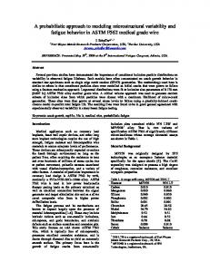
1) Bolt-Type Connection The processes for bolt-type GC lifting and installation are shown in Figure 6: tower crane connection of member → tilt-up → lifting and moving → positioning → temporary bolting work → perpendicularity check → tower crane clear of member → disconnection of tower crane; these processes last for 17 minutes in total. Assuming that the average vertical lifting height is a 12story apartment building (1 floor = 2.9 m) and the rated tower crane speed is 40 m/min, the vertical tower crane
1. Towercrane connection of member
(1min)
2. Tilt-up
(1min)
3. Lifting and moving
(3min)
4. Positioning
(2min)
5. Coupling
(4min)
6. Inspection of vertical angle
(2min)
10
15
20
FIGURE VII INSTALLATION ACTIVITIES AND TIME FOR COUPLER-TYPE GC
Based on the motion study conducted at the local site for the product used in this study, the time required for connection of 12 couplers for 12 GC connections is calculated as 18 seconds per coupler. Thus, sufficient installation time for 1 coupler is calculated as 20 seconds [12]. Thus, the installation process for 39 upper GCs with 15 KICEM Journal of Construction Engineering and Project Management
Constructability Analysis of Green Column at the Low Bending Moment Zone
TABLE III CALCULATING THE INSTALLATION TIME FOR THE THREE GC TYPES WORKING TIME, MINIMUM COST EXPECTING (MCX) Time (min.) MCX (%) Typical floor (comparison Classifications Each Notes (1floor, 39 of C type) column columns)
coupler-type connections at the study site requires 507 minutes. 3) Sleeve-Type Connection The processes for sleeve-type GC lifting and installation are shown in Figure 8: tower crane connection of member → tilt-up → lifting and moving → positioning → sleeve setting → propping work; these processes last for 14 minutes in total. While the propping work is in progress, a perpendicular check, getting the tower crane clear of the member, and disconnection of the tower crane are simultaneously executed, so they are excluded from the calculation of installation time. Sleeve type
17
663
100%
Coupler type
13
507
76%
Sleeve type
14
546
82%
Each column: 4 minutes MCX; Typical floor: 156 minutes MCX Each column: 4 minutes MCX; Typical floor: 117 minutes MCX
B. Comparison of Costs for the Connection Types time
5
Process 1. Towercrane connection of member
(1min)
2. Tilt-up
(1min)
3. Lifting and moving
(3min)
4. Positioning
(2min)
5. Sleeve setting
(4min)
6. Proping work
(3min)
10
15
20
Given the same performance and working environment, we calculate the quantity of materials input for each connection type and then the cost to use it, to efficiently evaluate the cost required for installation. The cost includes steel, steel frame installation fee, mortar, rebar, rebar link material cost (couplers, bolts and sleeves) and screwed rebar fee, which are used for each GC connection type. This is calculated based on the contractual unit cost applied to the actual site, according to price information (as of December 2012) and the standard estimate published by the Construction Association of Korea [13]. The cost of a joint connection is expressed in material cost including labor cost, plus the tower crane rental fee used for each GC installation calculated separately; the cost for temporary work is excluded from the cost calculation.
FIGURE VIII INSTALLATION ACTIVITIES AND TIME FOR SLEEVE-TYPE GC
The time for setting 12 sleeves and performing the grouting work for GC connections is calculated based on the motion study conducted at the local site [6], and the prop is installed at the vertical link member considering the characteristics of 3-floor 1-section GC. When it is fixed, the tower crane is disconnected. Thus, the installation process for 39 upper GCs using the sleevetype connections at the study site requires 546 minutes. The installation time required for each GC connection type applied to the study site is given in Table 3. The longest working time required is for the bolting type, followed by the sleeve type, and then the coupler type. The installation time of the sleeve type was 24% less than that of the bolt type, and the installation time of the coupler type was about 7% less than that of the sleeve type. Therefore, adopting the coupler-type GC can save 5.7 days of installation time compared to using the bolt type, based on working days for a typical 20-story apartment building. This demonstrates that applying the GF approach will greatly reduce the steel frame construction period compared to using the bearing wall approach [9]. Furthermore, it is anticipated that the construction period can be reduced even more by applying the low moment connection method developed in this study.
1) Bolt-Type Connection The bolt-type joint is installed using the bolt-type rebar connection plate as shown in Figure 1. As described in Table 4, the bolt-type rebar connection plate is composed of upper/lower plates and plate link materials, and it requires 0.053 tons per column, which means that 2.082 tons are required for 39 columns per floor. Additionally, 936 pieces of screwed rebar are needed per floor, and the manufacturing cost that includes a delivery fee per piece is 1,750 won, for a total of 1,638,000 won. A total of 24 bolts are required per column, 12 each for the upper and lower parts. For the bolt type, a tower crane is used for 15 minutes to install a column (Figure 6), so 9.75 hours are required per floor. This is calculated based on the monthly rental fee of a T-type 12-ton tower crane (based on 200-hour operation), which includes the operator labor cost. The PC installation cost is calculated as 320.729 won/m3 by converting the amount per unit area based on the on-site estimate, and the cost for the upper/lower column joint grouting is calculated as 48,880 won/m3 based on the Price Information. Therefore, the cost for installing the bolt-type low-moment joint at the study site is 6,426,406 won in total.
16 Vol.3, No.4 / Dec 2013
Bolt type
Sung-Ho Lee, Jun-Yong Park, Chae-Yeon Lim, and Sun-Kuk Kim
2) Coupler-Type Connection
install a column for the sleeve-type connection (Figure 8), and 13.7 hours are required per floor. The tower crane operating time is longer than for the bolt and coupler types. This is because the member connected to the tower crane cannot be disconnected until the propping is completed, to achieve safe erection and perpendicularity of the 3-floor 1-section column that is 9 m high, even if the rebar is inserted in the sleeve. The PC installation cost is the same as for the other two types, and the cost for upper/lower column joint grouting is calculated as 180,063 won based on the Price Information. Therefore, the cost for installing the sleeve-type low-moment joint at the study site is 5,800,843 won in total. Comparing the different installation costs of the three LMZ-GC types of connections, the bolt type is 6,426,406 won, the coupler type is 5,985,664 won and the sleeve type is 5,800,843 won. As shown in Table 4, the costs of individual items for the different connection types may increase, but currently, the cost for installing the sleeve type is lower than for the other types: 10% lower than the bolt type and 3% lower than the coupler type.
The coupler-type joint is installed using the PC setting block as shown in Figure 1. The cost for installing the coupler type joint is composed of the costs for installing the PC setting blocks, couplers and screwed rebar, as listed in Table 4. The cost of screwed rebar is the same as that of the same-sized deformed rebar. Per floor, 468 couplers are required, which is 12 couplers per column, and the total cost is 3,416,400 won. A lock bolt has the role of safely installing the coupler on the right spot on the screwed rebar and preventing loosening [12], and it is installed at the upper/lower coupler. Per floor, 936 lock bolts are required. The cost for coupler grouting to fill in the permitted tolerance, which is up to 20 mm [12], is included in the coupler price. PC setting blocks are used to secure a space when installing the screwed rebar and to transmit vertical loads when connecting the upper/lower columns. The cost for manufacturing each block is calculated as 3,000 won based on the concrete strength of 300 kgf/m2. A tower crane is used for 11 minutes to install a column for the coupler type (Figure 7), which means 7.15 hours are required per floor. The PC installation cost is 446,455 won per column of volume 1.39 m3, and the cost for upper/lower column joint grouting is calculated as 53,130 won/m3 based on the Price Information. Therefore, the cost for installing the coupler-type lowmoment joint at the study site is 5,985,664 won in total.
C. Comparison of Quality/Safety for the Connection Types GF has been shown to be superior in terms of structural safety and quality through experiments, analyses and site study applications [2,3,4]. A questionnaire on the quality and safety performance of the low-moment connection method was distributed to experts in related fields (22 engineers who had worked at GF-applied sites for 5 years or more were chosen). Safety factors examined were drop, fall and collision, and the quality factor was the performance of the joint work. After the survey of experts was conducted, the FD-AHP method was used to compare the reported quality/safety of each type of GC low-moment connection.
3) Sleeve-Type Connection The sleeve-type joint is shown in Figure 1, and no other special devices or materials other than the sleeves are used. The costs for installing the sleeve-type joint are listed in Table 4. For each column, 12 sleeves are required, and the cost for sleeve grouting to connect the upper column sleeve to the lower column rebar is 2,200 won per location. A tower crane is used for 14 minutes to
Description
Unit
TABLE IV CONNECTION COSTS OF THE THREE TYPES OF GCS Quantity Unit price Bolt Coupler Sleeve
Cost Bolt
Coupler
Sleeve
Str. Steel
ton
1,160,000
2.082
-
-
2,415,120
-
-
Str. Steel production
ton
240,000
2.082
-
-
499,632
-
-
Screwed rebar
EA
1,750
936
-
-
1,638,000
-
-
Bolt
EA
288
468
-
-
134,784
-
-
Coupler
EA
7,300
-
468
-
-
3,416,400
-
Lock bolt
EA
320
-
936
-
-
299,520
-
Coupler grouting
EA
-
-
468
-
-
-
-
Reinforcement block
EA
3,000
-
39
-
-
117,000
-
Sleeve
EA
7,500
-
-
468
-
-
3,510,000
Sleeve grouting
EA
2,200
-
-
468
-
-
1,029,600
T/C
EQH
46,500
9.75
7.15
13.65
453,375
332,475
634,725
3
320,729
1.39
1.39
1.39
446,455
446,455
446,455
3
912,000
0.92
1.51
0.20
839,040
1,373,814
180,063
6,426,406
5,985,664
5,800,843
PC Installation Grouting mortar
m m
Totals
17 KICEM Journal of Construction Engineering and Project Management
Constructability Analysis of Green Column at the Low Bending Moment Zone
The FD-AHP method is a new decision-making model that utilizes the AHP-based fuzzy theory and the Delphi technique, which quantifies evaluation results on decision-making issues for which the most suitable choice is to be selected among multiple alternatives [14]. Table 5 gives the results of the quality and safety evaluations based on the FD-AHP. The data from the survey of experts should be qualified via a consistency review (consistency index < 0.1). The 12 sets of data in this study showed 100% qualification in the consistency index. Therefore, the critical factors were selected from this data. The data from the survey can be objectified through calculation of minimum, maximum and geometric mean. Considering the minimum and maximum values as extremes in the decision making process, the optimal value can be defined as the geometric mean value. Equation 1 expresses the minimum, maximum and geometric average as a, b and c, respectively.
of the three types are summarized in Table 5, showing that the quality is viewed to be outstanding, in the order of most to least often, for the coupler type, the bolt type and the sleeve type. 2) Comparison of Safety for the Connection Types Safety-related questionnaire items included falling, dropping, clashing and constricting. The risk of falling depends on the order of installing the GC connection columns. In addition, the members or equipment may fall, and the connected materials and parts may clash and constrict, when lifting and installing the columns. The results of the analyses on the questionnaire data using the FD-AHP method show that the safety of the bolt type is 37%, the coupler type is 37%, and the sleeve type is 26%, as shown in Table 5, demonstrating that the safety evaluations of the bolt and coupler types are similar and slightly better than that of the sleeve type. D. Comprehensive Evaluation per Connection Type
(1)
The data regarding the installation time, cost, quality, and safety analyzed previously provide a comprehensive comparison of the features of the three types of GC connections. These features are listed in Table 6.
These calculated values are presented in a fuzzy matrix. Then, the column vector geometric mean method is used to calculate the fuzzy vector from the fuzzy matrix. The fuzzy vector consists of the minimum, geometric mean and maximum values.
TABLE VI COMPARISON OF ALL EXAMINED FEATURES OF THE THREE TYPES OF GCS
Description
(2)
The final weight vector is calculated using the geometric mean method. The sum of weights from the evaluation factors should be one. The weights are shown in Table 5. TABLE V CONNECTION COSTS OF THE THREE TYPES OF GCS Bolt Coupler Sleeve type type Type 32.06%
45.40%
22.54%
100.00%
Safety
37.13%
37.13%
25.74%
100.00%
1) Comparison of Quality for the Connection Types
Quality (%)
Safety (%)
Bolt type
663
6,426
32.06
37.13
Coupler type
507
5,985
45.40
37.13
Sleeve type
546
5,800
22.54
25.74
V. CONCLUSIONS
Quality-related questionnaire items were assessed by reflecting the GC features. The items included questions regarding perpendicularity based on the detailed process of installing the GC joint, grouting compaction /effectiveness, structural safety of the coupler/bolt fastening and excellence of the screwed rebar. Results of the questionnaire data analyses using the FD-AHP method show that 45%, 32% and 23% assessed the coupler, bolt and sleeve types as outstanding, respectively. These results show that the quality of the GC lowmoment joint using the coupler-type connection is viewed by experts as the most superior. The reported evaluations
Generally, the PC column-column connection is performed at the boundary of each floor where the highest moment is generated, which is undesirable in terms of structural safety. To resolve this problem, the connection of columns at the low-bending-moment zone is developed. This study investigated three low-bending moment connection types, examining their features and implementations at the study site, to compare and analyze the installation time, cost, quality and safety, and arrives at the following conclusions. First, the structural safety of low-bending-moment
18 Vol.3, No.4 / Dec 2013
Cost (1,000 won)
Since the upper column must be completely connected to the lower column while taking into account the characteristics of the 3-floor 1-section columns, the bolt and coupler types provide better constructability and structural safety. Further, compared to the bolt type, the coupler type demonstrated cost reduction of about 7%, and the sleeve type reduced cost about 10%. Considering the various performance differences among the low-moment connection types with respect to installation time, cost, quality and safety, the coupler type is the most outstanding type overall.
Total
Quality
Time (min)
Sung-Ho Lee, Jun-Yong Park, Chae-Yeon Lim, and Sun-Kuk Kim
[12] Tokyo tekko, “TOKYO TEKKO TRADING CO.,LTD.”, Available at http://www.tokyotekko.co.jp/products/product03.html, accessed on 8th may 2013 [13] Construction Association of Korea, “Investment expenditures of Korea construction market”, Available at https://cmpi.co.kr, accessed on 25th October 2012 [14] Q. Zheng, D.H. Lee, S.H. Lee, J.T. Kim, S.K. Kim, “A Health Performance Evaluation Model of Apartment Building Indoor Air Quality”, Indoor and Built Environment, vol. 20, no. 1, pp. 26-35, 2011 [15] J.T. O’Connor, S.E. Rusch, M.J. Schulz, “Constructability concepts for engineering and procurement”, Journal of Construction Engineering Management, 113, pp.235-248, 1987
connections was confirmed, and the constructability for installing the columns was increased when this connection method was applied. Second, the coupler type that uses the screwed rebar demonstrated outstanding results for cost, installation time, quality and safety. These results indicate that the use of more screwed rebar using the low-bending-moment connection method will develop GF, a resource-saving, long-life-span architectural system. Third, since the connection is performed at the middle of the column, a low-bending-moment zone, this method improved constructability. The study results will be utilized as data to research and develop new construction methods that may reduce installation time, improve quality and constructability, enhance safety and reduce costs when building post-andlintel constructions in the near future. ACKNOWLEDGEMENTS This work was supported by a National Research Foundation of Korea (NRF) grant funded by the Korean government (MSIP) (No. 2008-0061908). REFERENCES K.J. Lee, “Precast Concrete”, 3rd ed., Seoul: Kimoondang, 2007 W.K. Hong, S.C. Park, J.M. Kim, S.I. Kim, S.G. Lee, “Experimental Study of Reinforced Concrete Beams Strengthened with a GFRP and CFRP Sheets”, The Structural Design of Tall and Special Buildings, vol. 19, no. 5, pp. 497-517, 2010 [3] W.K. Hong, S.C. Park, H.C. Lee, J.M. Kim, S.I. Kim, S.G. Lee, K.J. Yoon, “Composite Beam Composed of Steel and Precast Concrete (Modularized Hybrid System). Part III: Application for a 19-Story Building”, The Structural Design of Tall and Special Buildings, vol. 19, no. 6, pp. 679-706, 2010 [4] W.K. Hong, S.I. Kim, S.C. Park, J.M. Kim, S.G. Lee, K.J. Yoon, S.K. Kim, “Composite Beam Composed of Steel and Precast Concrete (Modularized Hybrid System). Part IV: Application for Multi-Residential Housings”, The Structural Design of Tall and Special Buildings, vol. 19, no. 7, pp. 707-727, 2010 [5] S.H. Kim, E.G. Choi, S.K. Kim, S.H. Lee, “An Improvement Case Study of Structural Work of Logistics Facility by Using PC Member”, Journal of the Korea Institute of Building Construction, vol. 10, no. 6, pp. 127-135, 2010 [6] K.H. Kim, T.O. Lee, S.H. Lee, S.K. Kim, “Comparative Analysis of Column Connection Characteristics of Green Frame”, Journal of the Korea Institute of Building Construction, vol. 12, no. 4, pp. 415-425, 2012 [7] C.Y. Lim, J.G. Joo, G.J. Lee, S.K. Kim, I”n-Situ Production Analysis of Composite Precast Concrete Members of Green Frame”, Journal of the Korea Institute of Building Construction, vol. 11, no. 5, pp. 501-514, 2011 [8] S.Y. Seo, S.J. Yoon, W.J. Lee, “Evaluation of Structural Performance the Hollow PC Column Joint Subjected to Cyclic Lateral Load”, Journal of the Korea Concrete Institute, vol. 20, no. 3, pp. 335-343, 2008 [9] S.H. Lee, S.E. Kim, G.H. Kim, J.K. Joo, S.K. Kim, “Analysis of Structural Work Scheduling of Green Frame ; Focusing on Apartment buildings”, Journal of the Korea Institute of Building Construction, vol. 11, no. 3, pp. 301-309, 2011 [10] S.H. Lee, J.K. Joo, J.T. Kim, S.K. Kim, “An Analysis of the CO2 Reduction Effect of a Column-Beam Structure Using Composite Precast”, Indoor and Built Environment, vol. 21, no. 1, pp. 150162, 2012 [11] J.K. Joo, S.E. Kim, S.H. Lee, G.J. Lee, S.K. Kim, “A Study on the Lifting Progress for Composite Precast Concrete Members of Green Frame”, Journal of the Construction Engineering and Management, vol. 13, no. 3, pp. 34-42, 2012 [1] [2]
19 KICEM Journal of Construction Engineering and Project Management