Proceduralization for Editing 3D Architectural Models ˙Ilke Demir Purdue University West Lafayette, IN
Daniel G. Aliaga Purdue University West Lafayette, IN
Bedrich Benes Purdue University West Lafayette, IN
[email protected]
[email protected]
[email protected]
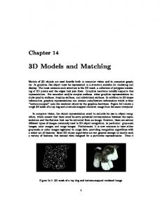
Figure 1. Overview. Original input model (left), versus new buildings synthesized by editing the extracted procedural representation.
Abstract
an easy to synthesize procedural form and allows for quick synthesis of visually similar buildings. In this paper, we introduce a novel inverse procedural modeling approach for architectural models that enables the intuitive synthesis of novel 3D architectural models.
Inverse procedural modeling discovers a procedural representation of an existing geometric model and the discovered procedural model then supports synthesizing new similar models. We introduce an automatic approach that generates a compact, efficient, and re-usable procedural representation of a polygonal 3D architectural model. This representation is then used for structure-aware editing and synthesis of new geometric models that resemble the original. Our framework captures the pattern hierarchy of the input model into a split tree data representation. A contextfree split grammar, supporting a hierarchical nesting of procedural rules, is extracted from the tree, which establishes the base of our interactive procedural editing engine. We show the application of our approach to a variety of architectural structures obtained by procedurally editing websourced models. The grammar generation takes a few minutes even for the most complex input and synthesis is fully interactive for buildings composed of up to 200k polygons.
Previous inverse procedural modeling work of architectural structures has focused on facades, point clouds, buildings, or cities. Facade methods (e.g., [34, 35]) provide compelling results but do not readily extend to 3D buildings. Building point cloud approaches (e.g., [3, 6, 12, 29]) focus on segmentation and on symmetry analysis for finding repetitions. Methods working with building models assume having both a segmented and a labeled model with structural constraints (e.g., [15]), multiple exemplars of the same building style in different configurations (e.g., [27]), segments cut only along curves within symmetric areas which limits the ability to process arbitrary building geometries (e.g., [8]), and/or restricted geometric shapes (e.g., [30]). Further, above methods only provide a procedural description and do not include integrated synthesis tools. To our knowledge, our method is the first to provide automatic inverse procedural modeling for synthesis of arbitrary 3D architectural structures by discovering a set of procedural rules representing the input model and providing intuitive and parameterized editing operations (Figure 1). Our approach processes a polygonal architectural model, segmented by a shape decomposition tool, without the need of any hierarchy, constraint, or shape restriction. The procedural rules, non-terminals, and terminals are then inferred from the collection. The output is an instantiation of a context-free split grammar including procedural hierarchies
1. Introduction Architectural models are important in computer graphics, virtual environments, and urban planning which puts a high demand on obtaining and editing those models. While procedural modeling has been shown to provide compelling architectural structures, creating detailed and realistic buildings needs time and extensive coding. In contrast, inverse procedural modeling converts existing building models into 1
with re-use of the grammar elements. Then, our method automatically determines a set of attachment constraints on the grammar elements to support style-preserving interactive editing and synthesis. The resulting grammar is compact editable via our GUI. Our method has two phases: • Proceduralization: the model is organized into a split tree, the nodes of the tree are inspected by a transformation space analysis to identify rules and their repetitions; the rules can be hierarchically organized, and can contain regular patterns of up to three dimensions. • Editing: the creation of novel buildings is enabled by our interactive system or by editing the grammar; our interactive system keeps the procedural model under the hood and provides GUI-based new rule generation, rule application, terminal replacement, resizing, and copy/paste operations. It also supports local and global retargeting that preserves the relative adjacencies by using a sparse least-squares optimization. We show the application of our approach to edit a variety of buildings, totaling up to 200K triangles per input building and over a million triangles after synthesis. We automatically applied our method to over 50 architectural models, most of which are from Google Warehouse. On a standard desktop computer, inferring the split grammar of a building takes a few minutes, and our interactive editing and synthesis tools can synthesize a new building in less than one second. The computed grammar is a text file containing hierarchies of parameterized rules and references to terminal symbols. Our main contributions include: • a novel and automatic inverse procedural modeling approach that converts a 3D architectural model into a procedural representation, • a structure discovery method to parse a collection of building components into a split tree, and to find a hierarchical nesting of patterns which can be output as a context-free split grammar, and • an interactive procedural engine for local and global style-preserving synthesis and editing of 3D models.
2. Related Work We relate our work to procedural and inverse procedural modeling, and shape editing. In addition, Supplemental Part C contains an itemized comparison to previous papers. Procedural Modeling is a powerful methodology used for modeling plants (e.g., [22]), cities (e.g., [20]), and other objects. Vanegas et al. [31] and Smelik et al. [24] present comprehensive surveys of procedural modeling. Procedural modeling has a well-established history in urban design such as shape grammars of Stiny et al.[26], the pattern language of Alexander et al. [1], and, more recently, the procedural buildings of Wonka et al. [33], of Muller et al. [18],
Figure 2. Overview. Our approach takes an input model, extracts components, finds patterns, constructs a split tree, builds a contextfree grammar, and enables interactive synthesis operations.
and of Schwarz et al. [23]. However, creating procedural rules requires knowledge of the modeling language and of the general style-codification process. While Lipp et al. [16] (and CityEngine) describe interactive editing systems for procedural buildings, they assume that procedural models are provided a priori. We also seek to exploit procedural modeling but we wish to avoid the tedious task of manually writing a set of parameterized procedural rules to encode a particular building style based on an input model. Inverse Procedural Building Modeling seeks parameterized grammar rules and/or parameter values that yield the provided model. Vanegas et al. [30] proposed an inverse procedural approach for reconstructing Manhattanworld buildings, but do not produce a grammar nor demonstrate editing. Bokeloh et al. [8] exploit the repetition of partially symmetric structures and enable building model synthesis. Nonetheless, their symmetry basis is surfaces, thus any 3D segmented input is not applicable as input. Talton et al. [27] find a probabilistic grammar capturing the patterns of a family of segmented and labeled hierarchical designs provided as input. Talton et al. [28] and Vanegas et al. [32] used Monte Carlo Markov Chain optimization to discover how to alter the parameters of a given procedural model of a building and/or of a city so as to yield an output satisfying a desired set of properties. Lastly, Demir et al. introduced several proceduralization techniques, applying inverse procedural modeling to point clouds [12] for improving the point cloud quality and providing procedural editing, to textured city models [10] for proceduralizing existing cities for synthesis, and Nishida et al. [19] applied it to sketching to facilitate creation of novel 3D content.
In contrast, our automatic approach produces a split grammar, supports arbitrary 3D architectural models (instead of just facades), creates hierarchical rules, does not need labeled input, and supports various editing tools. Moreover, many of the mentioned approaches assume the procedural model is provided and only the parameter values need to be discovered. In contrast, our method assumes no knowledge of the procedural model and generates both grammar and parameter values. Shape Editing covers multiple structure-aware editing methodologies which have also been proposed for polygonal models (e.g., see survey by Mitra et al. [17]). They differ mainly in the level of automation, types of processed geometries, support for hierarchical patterns, creation of an explicit grammar, and editing flexibility and control. For example, Pauly et al. [21] find patterns with translational, rotational, and cylindrical grid arrangements. However, their objective is not the generation of a grammar, little editing control is provided, and hierarchical patterns are not supported. Some previous work [5, 13, 15, 36] support hierarchical patterns but require user assistance. Lin et al. [15] supports only 1D patterns while Kalogerakis et al. [13] offer limited editing control. The approaches of Bokeloh et al. [7, 9] provide flexible shape editing control, but no hierarchical pattern support is provided and patterns must be either 1D or only translational. Our interactive approach is fully automatic, supports a larger family of patterns, and a hierarchical rule organization is also discovered. Our method generates an explicit context-free split grammar and allows both local and global structure-aware synthesis. Conflicting editing goals are resolved quickly using a sparse linear least squares optimization rather than satisfying the desired edits in an a priori determined importance order as in Zheng et al. [36] or by solving a dense matrix with SVD as in Bokeloh et al. [9].
3. Proceduralization Proceduralization takes an input architectural model and automatically generates an instance of a split grammar G that represents the model. In this section, we briefly describe the steps for proceduralization.
3.1. Segmentation and Component Labeling The input to our approach is a 3D polygonal mesh that can be either manually or automatically segmented. Then, our method performs the component labeling. Suitable segmentation can be performed using an architectural segmentation algorithm such as Demir et al. [11], Attene et al. [4], or Kalogerakis et al. [14]. In this paper, we primarily use Demir et al. [11], since they focus on buildings, but we show results using other segmentation algorithms as well (Figure 8). After segmenting input model into components, we compute the bounding box of each component and do
a check of triangle counts and bounding box dimensions to ensure the labels are accurate (if labels are given by the segmentation approach) or we compare the convex hull of the components in addition to the previous properties to label similar components (if no labels are assigned). However most of the time the success of the labeling depends on the segmentation approach, see the discussion of [11]. The labeled components are then passed to the grammar extraction step (Section 3.3). This segmentation and labeling can be considered a 3D extension of the layout concept by [34].
3.2. Split Grammar Definition Our context-free split grammar notation is inspired by other notations used in urban modeling (e.g., [18]), though we define some compact extensions (Figure 3). The core operation of the grammar is a volumetric split operation. Split Tree. A split operation is described by a point dividing an enclosing box into octants and a selection of one of the octants for subsequent use. The split tree T is composed of a set of nodes P = {p0 , . . . , pN }, with p0 being the root node, and edges epi pj storing a point split operation between a parent node pi and its child node pj . In our implementation, a split operation is written as: pj = split(pi , vx , vy , vz , q),
(1)
where pi is the node to split by a pivot point (vx , vy , vz ), and octant q ∈ [1, 8] is extracted. The octant q defines the subvolume corresponding to node pj and it can be logically assigned to either a terminal or a nonterminal of the G. Children nodes have geometric parameters relative to their parent node’s space. Each node also contains additional information about size, group label, axis-aligned box-shaped volume, neighbors in the adjacency graph, global position, and optionally a reference to component geometry. Repetition Handling. Our grammar also supports the definition and repeated application of rules (i.e., patterns) – see Figure 4. Moreover, any regular or irregular pattern can be encoded as a subtree of splits and exported as a parametrized rule. However, not all patterns and transformations are explicitly recognized and parameterized. Pauly et al. [21] defines and recognizes regular patterns involving 1-parameter groups of translation, rotation and scale. Our application domain is architecture where scaling does not commonly occur and thus we do not explicitly recognize the repetitions where the units have varying scale. However a scaling edit on a terminal/rule is supported and preserved by our system. Using the same categorization as [21] our approach recognizes up to k ≤ 3 parameter groups of translation. Patterns that contain rotation are also detected but there is no special naming convention as subdivide, instead they are exported as separate rules with their parameters. A rule is defined as: Rule R1(pi ) = {...}, where R1 is the rule label, and pi is the node to which the collection of
Figure 3. Grammar. (a) Initial model and its extracted grammar. (b) New model with more windows produced by (c) a grammar modification. (d) An army of buildings created by (e) multiple applications of a newly generated rule. (f) The result of random floors.
with respect to each axis. Grammar. Our context-free split grammar is G = hV, Σ, R, ωi ,
Figure 4. Rule Support. (a) Multiple applications of R1, (b) A grid pattern of R1, (c) An irregular pattern of R1, captured by R2.
where G is the grammar, V is the set of non-terminals (i.e., root nodes of subtrees each representing a rule), Σ is the set of terminals (i.e., leaves of T ), R is the collection of rules (i.e., split operations), and ω is a starting axiom (i.e., the root node p0 ). Moreover, terminals are output to 3D model files (e.g., OBJ files). Since the output can have arbitrary polygonal data, G supports a variety of terminals, including modern building architecture with curved surfaces.
3.3. Grammar Extraction split operations {...} will be applied. A rule can be applied following a k ≤ 3 parameter group translation pattern with a subdivide command. Such patterns do not need to be axisaligned but must be regularly spaced where each element of the pattern may vary by translation. Different applications of the rule may vary by translation and rotation, and do not need to be regularly spaced. A rule application is written as R1(pi ), or
(2)
R1(subdivide(pi , sx , sy , sz [, dx , dy , dz ])),
(3)
where (2) corresponds to one application of rule R1 to node pi , and (3) is an application pattern of rule R1 to node pi subdivided into sx × sy × sz nodes. The optional vector d = [dx , dy , dz ] further defines the pattern: for k = 1, it is the axis of repetition; for k = 2, it is the normal to the plane of repetition, and for k = 3, it is a triplet of Euler angles
Given the segmented and labeled input model, our method creates a split tree, labels rules, discovers patterns of repetition, and exports G. Tree Construction. In this first step, the labeled input components are organized into a top-down constructed split tree T (Supplemental Part A). First, all components are placed in a list sorted by decreasing volume of their bounding boxes. Then, the root node p0 is created using the entire building bounding box. Afterwards, the next largest component ci from the list is inserted into T . The insertion performs a top-down search to find the parent node Ppci with the tightest fitting bounding box to ci . Our method computes the parameters of one (or two) split operations that obtain ci ’s bounding box from Ppci . With the split on the edge, the node pci is created, and the component’s geometry is stored in pci with vertices relative to the node’s bounding box. This step repeats until all components are inserted.
Note that the bounding boxes are used only as containers to organize the actual geometry within. The vertex coordinates relative to the node boxes are converted to global coordinates at export time. Thus, the nodes can represent various shapes including curved and complex parts; see Supplemental Part E for more examples from modern architecture. Rule Labeling. In this next step, T is labeled to identify repeating and non-repeating subtrees – i.e., rules. This approach is inspired by the tree matching algorithms of Apostolico and Galil [2]. Our system performs two phases of rule labeling: a top-down phase to ensure that similar subtrees are used for the same rule, and a bottom-up phase to extend subtrees of the same rule to include their parent nodes. The top-down phase performs a level order comparison of same-label nodes. The comparison includes the node properties as well as the topology of the subtrees. As previously mentioned, the subtree may contain some intermediate nodes that were created by the split operator to partition a parent box into a child box – we encode those branches as a “don’t care path” [2] without changing the breadthfirst comparison order. During this comparison, roots of subtrees with similar nodes are marked as repeating occurrences of the same label. If a subtree differs from its group, it is simply given a new label. This process ensures canonization (so that the subtrees are replaceable). The bottom-up phase carries the labeling up the tree by synchronously comparing parents of same-label root nodes. If parents are also similar, then labels are bubbled up to their parents. In this way, the patterns are caught higher in the tree, enabling better repetition detection and rule re-use. Pattern Discovery. At this step, an iterative method is performed so as to identify the pattern of repetition of the grammar rules. To explicitly discover patterns, we use a transformation space analysis similar to Stava et al. [25]. Our method computes the pairwise distances along each of the x, y, and z axis between all subtree root nodes with same rule label. Then, we search for the smallest distance that almost exactly divides all other distances along each axis. Multiple occurrences of a rule are joined under one node. Given high repetition counts along the x, y, and z axis or exact repetitions, the discovered pattern will be output using the subdivide operation. The smallest distances, the number of occurrences, and the global orientation are converted into the k-parameter pattern use of the subdivide operation (Eqn (3), Figure 4b). For other repetitive use of rules, the common ancestor is output as a rule (Eqn (2), Figure 4c)). Nonrepeating and low-repetition subtrees are not considered a pattern and are output as separate rules (Figure 4a). As an example, the pairwise distances from the upper left window for Figure 4b would be (5,0), (10,0), (0,3), (5,3), (10,5), for upper middle window (5,0), (5,3), (0,3), (5,3), for upper right window: (10,3), (5,3), (0,3), for lower left window: (5,0), (10,0), and for lower middle window: (5,0).
If we take the modulo of longer distances (10 modulo 5), the pattern distance is revealed as (5,3) and the frequency of repetition is 3x2x1 along each of the x,y,z axis. The result is the rule “R1(subdivide(pi ,3,2,1))”. Grammar Exportation. Finally, our method computes a declare-before-use rule ordering so that contained rules are listed before the containing rules. After outputting rule definitions, the non-repeating part of the grammar is output. Further, leaf nodes Σ contain actual geometry. In this manner, i) a building model may contain geometry that would be inefficient to represent with a sequence of split operations (e.g., a curved surface) or edited geometry that is unsupported by the current algorithm (e.g., scaling), and ii) repeating structures are stored only once, hence reduce the model size. For example, the procedural model (including terminals) of Figure 3d,f is 169 KB on disk, whereas their corresponding models are 1.5MB and 2.2MB, respectively.
4. Editing Our framework enables intuitive interactive editing operations. Automatically adjusting the patterns in a forward procedural modeling way (e.g., Figures 3c-f) creates new instances of the building, which would have been more time consuming if manually modeled. However, the user cannot always easily determine the needed grammar changes because it is hard to foresee the outcome of a grammar change since it might have global effects on all instances of a rule. Thus, we provide a GUI to perform local and global edits as well as specialized building alterations. The user can also constrain editing to a local region, thus opting to leave some of the features of the original building unaffected. Altogether, our interactive system supports three fundamental operations: 1) resize, 2) split and join, and 3) copy/paste/add/remove. After editing, the new building is exported as a model with the preserved component labels being used as texture groups. In contrast to Lipp et al. [16], our GUI provides stroke-based interaction where the user only interacts with the geometric model, and the procedural model (as well as its parameters) are kept under the hood.
4.1. Structure Preserving Resize Our method can perform a structure-preserving resize on a user-defined area. It changes multiple split operation parameters, which is not straightforward to perform via textediting. The adjacency relations of the nodes in the specified area are converted into attachment equations (Figure 5 and Supplemental Part D). Then, the optimization finds the best set of split parameters that yield the desired new position(s), maintaining the adjacencies. Further, if a tree node is excessively resized, it will get split (or joined). All editing operations are demonstrated in our supplemental video. Attachment Equations. A tree node pi ‘s axisaligned box is represented by two vertices: the minimum-
Figure 5. Attachment Equations. Examples of (a) corner, (b) edge, (c) plane, (d) volume, (e) size, and (f) position attachments.
valued vertex (aix , aiy , aiz ) and the maximum-valued vertex (bix , biy , biz ) (i.e., {aix , aiy , aiz } ≤ {bix , biy , biz }). Two constraints can be imposed on the node vertex coordinates: coordinate equality (ai = bj or ai − bj = k) and coordinate-pair overlap. The latter corresponds to ensuring that the pairwise ratios are constant. k1ij∗ =
bi − aj∗ bj∗ − ai∗ and k2ij∗ = ∗ bi∗ − ai∗ bi∗ − ai∗
(4)
In other words, keeping the ratios equal to their original value will ensure that the amount of overlap is maintained even if vertices are moved or scaled. Using these constraints, we define seven attachment equations (see Figure 5 and Supplemental Part D) using the minimum-valued and maximum-valued bounding box vertices of nodes pi and pj : 1. Ground: attaches building to ground (e.g., aiz = 0). 2. Corner: attaches corners (e.g., ai = bj ). 3. Edge: ensures edge overlaps are kept relatively the same (e.g. ∆k1ij∗ = 0, ∆k2ij∗ = 0, ∗ ∈ {x, y, z}). 4. Plane: ensures plane overlaps are kept relatively the same (e.g. ∆k1ij∗ = 0 and ∆k2ij∗ = 0 where ∗ is two of {x, y, z}). 5. Volume: ensures volume overlaps are kept relatively the same (e.g. ∆k1ij∗ = 0 and ∆k2ij∗ = 0 where ∗ is each of {x, y, z}). Note: volume attachment does not mean containment; i.e., children of a node are not volume-attached to their parent. 6. Size: if one or more dimensions of a node are unattached at only one end, this equation attempts to keep the original size (e.g., ∆(bi − ai ) = 0). 7. Position: if one or more dimensions of a node are unattached at both ends, this equation attempts to keep the original position of the node (e.g., ∆ai = 0).
Attachment Optimization. After a node or subtree has been edited, the attachment optimization solves for the new ai ‘s and bi ‘s for each pi in the area of effect. We place at least three of the aforementioned linear equations per vertex into a large and sparse linear least squares formulation that can be quickly solved. During a setup phase, the system places the affected nodes in a processing queue following a breadth first order of their spatial adjacency to the main edited node(s). To save time, children of affected pi ’s are not enqueued, instead they are re-derived automatically from their parents after the optimization. The system marks whether all dimensions of ai ’s and bi ’s of all effected pi ’s are involved in at least one of the attachment equations. Moreover, the optimizer assigns weights per attachment type in order to normalize the equation values. In addition, we observed that the relative importance of the volume attachment is lower because it is harder to perceive the difference in volume overlaps. The system is guaranteed to never be under-constrained thanks to the attachments 5 and 6, and is only mildly overconstrained thanks to the marking process. In the former case, the use of position attachments prevents flipping the node’s vertices (i.e., negative box sizes). In the latter case, flipping is possible, but in practice it does not occur because solver finds a solution closest to the original configuration. The new vertex values define the tree node boxes. If a box is stretched by more than 1.8x of its initial size, then it will be split in two copies of the node (or the subtree); conversely, if a box is squeezed to less than 0.4x of its initial size and the adjacent boxes are siblings of the same node, then they are joined under one node. The new nodes are put in the processing queue. Hence, the process may be recursive (e.g., a very long wall may become 16 small walls in just one step if stretched enough). Therefore, the resize process can itself create new rules and patterns. Finally, the split operation parameters and neighborhood information are recomputed via our optimization. The topology of the terminal elements is unaffected by resizing because their vertex positions are relative to their volume. Also, the use of the bounding boxes is for ensuring the integrity of coordinate attachments and does not limit editing to box-shaped geometry (Supplemental Figure 6).
4.2. Split or Join The user can either split or join a subtree. To split, the user draws a split plane. The “splitted” geometry is divided into two and a split operation is inserted into the tree yielding the two new nodes. Then, the original node’s subtree is duplicated and placed in each of those two new nodes. Join is the inverse operation that merges and then creates a new rule. If user selects a subset to join, the subtrees are joined to form a single subtree. However, unlike split, join operation is topological, and if to-be-joined nodes have similar
subtrees, then a rule is created with the repetition, else they are joined under one node. This join operation is also used to make the pattern subtrees canonical as in Section 3.3.
4.3. Copy and Paste Copy/paste operations correspond to selecting existing rules and altering them, changing terminals, or forming a new rule. First, the user selects some part of the building with our GUI and the corresponding nodes of the selected region are joined to become the source. Then, the user chooses the destination geometry, and the content is similarly joined. The copy-and-paste operation is then performed by either inserting or replacing the source, and either filling or deriving from the destination. In particular, • insert/replace: the source is inserted in-between the destination root node and its subtree, where destination patterns are preserved in the lower levels, or the source replaces the destination, as the usual copy-and-paste where the content of the destination is lost; and • fill/derive: the source is used to fill the destination’s volume by repetitively placing the source so as to maintain its approximate aspect ratio (as a procedural copy-and-paste), or the relative parameters of the source node are used to derive its shape as it is placed within the destination volume.
Figure 6. Models. The decomposition of examples into components, number of discovered rules and number of unique terminals.
in C++, uses Qt and OpenGL, and runs on a desktop computer clocked at 3.40GHz with an NVIDIA GTX680 card. Photorealistic renderings were done with Maya. A procedural representation of an input model is generated in minutes and then can be edited interactively. The time to perform a local interactive GUI-based edit is under one second. A single global interactive edit may take up to 30 seconds for our largest buildings (i.e., 20 thousand equations). Our interactive editing can handle relatively larger models faster than previous work because we solve a sparse linear least squares system rather than performing a dense SVD computation.
In all cases, the copied subtree is rotated and fit so that its dominant orientation matches that of the destination.
4.4. Model Output The new model can be saved in .OBJ format anytime during the editing session. When requested, the relative vertex positions in each node is converted to global locations. Then, normals are calculated according to the current vertices. The pattern information is used to create material groups suitable for texture/material properties.
4.5. Structure Preserving Property The interactive editing part works on the underlying tree representation and on the adjacency graph of the nodes. For the first case, the procedural editing part is based on changing rule parameters and fitting rules in defined spaces, thus no invalid geometries are produced – only re-use of existing patterns occurs within their relative coordinate frames. For the second case, the adjacencies between the nodes are preserved by the linear system, thus invalid configurations such as windows hanging in empty space cannot occur. The integrity is guaranteed by the attachment constraints.
5. Results We used our system to detect procedural representations of a variety of architectural models and to perform a multitude of edits (see also video). Our system is implemented
Figure 7. Grammar Editing. (a) Inter-building rules (circled are applied to shorter one). (b) Intra-building rules: right wall adapts, left wall is filled. (c-e) New rules: 4th floor is applied to the other.
Models. Figure 6 provides a summary of a subset of our architectural models and their decomposition into number of building components, number of discovered rules, and number of unique terminal symbols. Twelve buildings in that table are from Google Warehouse and the rest is output of a well-known 3D building modeling program (Rev-it). Overall, we tested our proceduralization framework on over 50 architectural models and produced corresponding grammars and edits. Style Transfer. Building editing and synthesis can be done by text-based grammar editing or by our interactive system. An example in Figure 7a demonstrates how rules from one building are re-used to synthesize a new building (e.g., “style transfer”). 7b shows an operation of interac-
tively copying rules from one part of a building to another. In 7c-e), the upper floor of the complex building is made into a rule and the corresponding split grammar is output. Then, a subset of the simpler building is selected and its content is converted by the rule producing the 2nd floor. Synthesis. Figure 9, Supplemental Figures 5, and 6 contain additional building examples. We show the original building (rendered photorealistically), the input components, one or more altered versions, and then one edited version rendered photo-realistically. The editing sessions are kept under 10 minutes for almost all models. Segmentation Using Other Methods. We applied our method to the segmentations resulting from three methods: Graphite, Meshlab, and Demir et al. [11] (see insets in Figure 8). Then the labeling for the first two methods is done by our approach as described in Section 3.1. In all cases, our method was able to extract a reasonable set of rules, though Demir et al.’s architectural method obtained the best set of labeled components. Nonetheless, these evaluations show that our method is decoupled from the segmentation and able to handle a variety of segmentations.
building mesh. However, if the input does not contain any repetition or is significantly under-segmented, the entire model is considered one element that leads to an uninteresting grammar. Supplemental Figure 2a and its statistics in Row 14 of Figure 6 is an example of this behavior. Our approach cannot detect the presence of varying scale between or within applications of the same rule. However, the user can perform an edit that includes re-scaling, without losing track of the pattern application. Finally, since we compute adjacencies using bounding boxes during editing, our approach does not ensure adjacent terminals have a compatible boundary. Nevertheless, in Figures 1 and Supplemental Part E, we show several edited buildings with curved surfaces where the user ensures terminal faces are compatible.
Figure 9. Interactive Editing. Results of interactive editing sessions of Revit models. (a,i) Original models. (b-g, j-m) Colorcoded terminals. (h,n) New buildings rendered photorealistically.
6. Conclusions and Future Work
Figure 8. Segmentation Methods. We show three buildings segmented by (top) Demir et. al [32], (middle) Graphite, and (bottom) Meshlab, and then labeled by our method. The insets show the pure segmentation (before labeling by out method).
As mentioned in Section 3, our terminals and grammar expressivity depend on how the input is segmented and labeled. We evaluated that sensitivity in Supplemental Part B, for different segmentations. We also experimented our approach on point clouds, documented in Part B. Limitations. Our approach is able to process any 3D
We address the problem of inverse procedural modeling by converting an architectural model into a split tree and extracting a context-free parameterized split grammar. Further, we created an interactive editing tool that supports building editing by either changing rule generation or changing rule parameters via a sparse linear least squares optimization. We demonstrated our method by editing many 3D building models. Our results show how structurepreserving edits can quickly and easily be made. There are several avenues of future work. i) We would like to extend our process to represent patterns with nonconstant spacing, as an extension of “subdivide”. ii) We are interested in processing other domains, such as plants or rigid bodies. A convenient approach would be using [21] to explicitly output the pattern parameters of such models. iii) Finally, we are considering ways to expand our split tree representation to work with interior building models.
7. Acknowledgments This research was funded in part by NSF CBET 1250232, NSF IIS 1302172, NSF CDS&E 1608762 and NSF EEC 1606396 awards. We also thank Matt Sackley for helping with some of the rendered building models, and Clark Cory for the modeling support.
References [1] C. Alexander, S. Ishikawa, and M. Silverstein. A Pattern Language: Towns, Buildings, Construction. Oxford University Press, New York, August 1977. 2 [2] A. Apostolico and Z. Galil, editors. Pattern Matching Algorithms. Oxford University Press, Oxford, UK, 1997. 5 [3] I. Armeni, O. Sener, A. R. Zamir, H. Jiang, I. Brilakis, M. Fischer, and S. Savarese. 3d semantic parsing of largescale indoor spaces. In Computer Vision and Pattern Recognition, 2016. 1 [4] M. Attene, B. Falcidieno, and M. Spagnuolo. Hierarchical mesh segmentation based on fitting primitives. Vis. Comp, 22(3):181–193, 2006. 3 [5] F. Bao, M. Schwarz, and P. Wonka. Procedural facade variations from a single layout. ACM Trans. Graph., 32(1):8:1– 8:13, 2013. 3 [6] A. Berner, M. Bokeloh, M. Wand, A. Schilling, and H.-P. Seidel. A graph-based approach to symmetry detection. In Proc. of the IEEE VGTC Conference on Point-Based Graphics, SPBG’08, pages 1–8, 2008. 1 [7] M. Bokeloh, M. Wand, V. Koltun, and H.-P. Seidel. Patternaware shape deformation using sliding dockers. ACM Trans. Graph., 30(6):123:1–123:10, 2011. 3 [8] M. Bokeloh, M. Wand, and H.-P. Seidel. A connection between partial symmetry and inverse procedural modeling. ACM Trans. Graph., 29(4):104:1–104:10, 2010. 1, 2 [9] M. Bokeloh, M. Wand, H.-P. Seidel, and V. Koltun. An algebraic model for parameterized shape editing. ACM Trans. Graph., 31(4):78:1–78:10, 2012. 3 [10] I. Demir, D. Aliaga, and B. Benes. Proceduralization of buildings at city scale. In 3DV, pages 456–463, 2014. 2 [11] I. Demir, D. G. Aliaga, and B. Benes. Coupled segmentation and similarity detection for architectural models. ACM Trans. Graph., 34(4):104:1–104:11, July 2015. 3, 8 [12] I. Demir, D. G. Aliaga, and B. Benes. Procedural editing of 3d building point clouds. International Conference on Computer Vision (ICCV), Dec 2015. 1, 2 [13] E. Kalogerakis, S. Chaudhuri, D. Koller, and V. Koltun. A probabilistic model for component-based shape synthesis. ACM Trans. Graph., 31(4):55:1–55:11, July 2012. 3 [14] E. Kalogerakis, A. Hertzmann, and K. Singh. Learning 3d mesh segmentation and labeling. ACM Trans. Graph., 29(4):102:1–102:12, 2010. 3 [15] J. Lin, D. Cohen-Or, H. Zhang, C. Liang, A. Sharf, O. Deussen, and B. Chen. Structure-preserving retargeting of irregular 3d architecture. ACM Trans. Graph., 30(6):183:1– 183:10, Dec. 2011. 1, 3 [16] M. Lipp, P. Wonka, and M. Wimmer. Interactive visual editing of grammars for procedural architecture. ACM Trans. Graph., 27(3):102:1–102:10, Aug. 2008. 2, 5 [17] N. Mitra, M. Wand, H. R. Zhang, D. Cohen-Or, V. Kim, and Q.-X. Huang. Structure-aware shape processing. In SIGGRAPH Asia 2013 Courses, SA ’13, pages 1:1–1:20, New York, NY, USA, 2013. ACM. 3 [18] P. M¨uller, P. Wonka, S. Haegler, A. Ulmer, and L. Van Gool. Procedural modeling of buildings. ACM Trans. Graph., 25(3):614–623, 2006. 2, 3
[19] G. Nishida, I. Garcia-Dorado, D. G. Aliaga, B. Benes, and A. Bousseau. Interactive sketching of urban procedural models. ACM Trans. Graph., 2016. 2 [20] Y. I. H. Parish and P. M¨uller. Procedural modeling of cities. In Proceedings of the 28th Annual Conference on Computer Graphics and Interactive Techniques, SIGGRAPH ’01, pages 301–308, New York, NY, USA, 2001. ACM. 2 [21] M. Pauly, N. J. Mitra, J. Wallner, H. Pottmann, and L. J. Guibas. Discovering structural regularity in 3d geometry. ACM Trans. Graph., 27(3):43:1–43:11, Aug. 2008. 3, 8 [22] P. Prusinkiewicz and A. Lindenmayer. The Algorithmic Beauty of Plants. Springer-Verlag New York, Inc., New York, NY, USA, 1990. 2 [23] M. Schwarz and P. Mller. Advanced procedural modeling of architecture. ACM Trans. Graph., 34(4), 2015. 2 [24] R. M. Smelik, T. Tutenel, R. Bidarra, and B. Benes. A survey on procedural modelling for virtual worlds. Comp. Graph. Forum, 33(6):31–50, 2014. 2 [25] O. Stava, B. Benes, R. Mech, D. G. Aliaga, and P. Kristof. Inverse procedural modeling by automatic generation of lsystems. Comp. Graph. Forum, 29(2):665–674, 2010. 5 [26] G. Stiny. Pictorial and formal aspects of shape and shape grammars. Interdisciplinary systems research. Birkh¨auser, 1975. 2 [27] J. Talton, L. Yang, R. Kumar, M. Lim, N. Goodman, and R. Mˇech. Learning design patterns with bayesian grammar induction. In Proceedings of the ACM UIST, UIST ’12, pages 63–74, New York, NY, USA, 2012. ACM. 1, 2 [28] J. O. Talton, Y. Lou, S. Lesser, J. Duke, R. Mˇech, and V. Koltun. Metropolis procedural modeling. ACM Trans. Graph., 30(2):11:1–11:14, Apr. 2011. 2 [29] A. Toshev, P. Mordohai, and B. Taskar. Detecting and parsing architecture at city scale from range data. In Computer Vision and Pattern Recognition, pages 398–405, 2010. 1 [30] C. A. Vanegas, D. G. Aliaga, and B. Benes. Building reconstruction using manhattan-world grammars. In Computer Vision and Pattern Recognition (CVPR), 2010 IEEE Conference on, pages 358–365, June 2010. 1, 2 [31] C. A. Vanegas, D. G. Aliaga, B. Benes, and P. A. Waddell. Interactive design of urban spaces using geometrical and behavioral modeling. In ACM SIGGRAPH Asia 2009 papers, pages 1–10, New York, NY, USA, 2009. ACM. 2 [32] C. A. Vanegas, I. Garcia-Dorado, D. G. Aliaga, B. Benes, and P. Waddell. Inverse design of urban procedural models. ACM Trans. Graph., 31(6):168:1–168:11, Nov. 2012. 2 [33] P. Wonka, M. Wimmer, F. Sillion, and W. Ribarsky. Instant architecture. ACM Trans. Graph., 22(3):669–677, 2003. 2 [34] F. Wu, D.-M. Yan, W. Dong, X. Zhang, and P. Wonka. Inverse procedural modeling of facade layouts. ACM Trans. Graph., 33(4):121:1–121:10, July 2014. 1, 3 [35] H. Zhang, K. Xu, W. Jiang, J. Lin, D. Cohen-Or, and B. Chen. Layered analysis of irregular facades via symmetry maximization. ACM Trans. Graph., 32(4):104:1–10, 2013. 1 [36] Y. Zheng, H. Fu, D. Cohen-Or, O. K.-C. Au, and C.-L. Tai. Component-wise controllers for structure-preserving shape manipulation. Comp Graph. Forum, 30(2):563–572, 2011. 3