From Design to Tools: Process Modeling and Enactment with PDE and PET M. Kuhrmanna , G. Kalusa , M. Thena , E. Wachtela a Technische
Universit¨at M¨unchen, Institut f¨ur Informatik – Software & Systems Engineering, Boltzmannstr. 3, 85748 Garching, Germany
Abstract In our research group we work on software development process modeling and particularly deal with the question how a defined development process can be brought to life in a project. Modeling of complex processes with hundreds of elements requires comprehensive tool support. Successful enactment of a process during project lifetime does depend on how well the process is supported by tools for project execution – among equally important factors that deal with psychological and organizational questions. To prove ideas developed in research and to ease our day-to-day work in industrial cooperations, we are developing many tools ourselves. In this paper, we present the Process Development Environment and the Process Enactment Tool Framework that support intuitive modeling of development processes and their enactment. We give an overview over the organization and the process of our tool development, challenges we are facing, and present the lessons learned from academic tool development both from the researchers’ and the students’ point of view. Keywords: meta modeling, process models, enactment, development organization, student team, academic tools
1. Introduction “Nice work with the process, but how does it support me during the project?” – it is such questions that we are facing in our day-to-day work with partners from industrial practice. Most of our projects deal with software development process design and enactment, especially with the question how a defined process can be applied and brought to life in a project. The software development processes that we deal with are based on formal meta-models. Not only are such processes perfectly suited to be supported by tools (e.g., for derivation of project plans, generation of artifact templates and documentation), tool support is a necessity during design (the German V-Modell XT process XML description file for example is 4.8 MB big with a couple of ten thousand elements). Some tools are available that partly suit common needs. Yet, many needs coming from industrial projects or ideas we would like to try out in the context of our own research are not addressed. We are therefore developing many special-purpose tools
Email addresses:
[email protected] (M. Kuhrmann),
[email protected] (G. Kalus),
[email protected] (M. Then),
[email protected] (E. Wachtel)
1
ourselves. These range from “quick and dirty” micro-tools up to comprehensive frameworks with a quality level close to commercial solutions. The tools that we are building cover all stages of the life cycle of a development process. We have tools for definition, design, and validation of process models. We have also built processaware tools for project execution. Our long-term goal is to cover the whole life cycle of the software development process from process design to its enactment with seamlessly integrated methods and tools. Challenges. Because our software is motivated by industrial cooperation projects and in use by industrial partners, we have to maintain certain quality standards with our software. However, as a university, we are no solution provider and do not have a professional development staff. In fact, we do not have “real” development resources. Most of the development work is done with and by students. This fact greatly influences the way that we (must) organize tool development. Some noteworthy implications are: • It is not easy to find students. • The duration of student theses is limited. • A thesis must contain conceptual and theoretical work. • It is hard to assess the qualification and suitability of students. • The results vary in quality and in how easy they can be integrated into our tools. • Researchers and students sometimes have different goals. • It is difficult to establish a meaningful development roadmap. • Our selected technology is usually not taught in lectures. Outline. Before explaining in greater detail the specific challenges with tool development in our research group in Section 3, we present the tools themselves in Section 2. We are covering only the tools developed at Technische Universit¨at M¨unchen in the research group Development Processes1 . Other research groups at our chair are also developing tools of considerable size and are facing similar challenges. In Section 4, we give an overview over our group’s organization that is a direct consequence of our experience with academic tool development during the last years. In Section 5, we describe the transfer strategy to promote our software. The paper is closed in Section 6 with a discussion and open questions with regards to academic tool development. 2. Process-aware Tools Historically, requirements coming from industrial cooperation projects as well as questions from our own research work have lead to the development of a couple of prototypical tools that were only used by ourselves. Over the years and many student projects later, some of 1 The chair for Software & Systems Engineering is organized in several competence centers. Each has a focus to a particular area of Software Engineering. The emphasis of the competence center Development Processes is the modeling of variable development processes and their systematic enactment.
2
the tools have outgrown the experimental stage and are now covering large parts of the life cycle of a software development process. In this section we first give a short impression of how we understand development process models and what we consider important for modeling and enactment of such processes. We then present our two flagship tools PDE (Section 2.2) and PET (Section 2.3). Finally, we give a short overview over some other (smaller) tools that we have developed or are developing. 2.1. The Life Cycle of a Development Process and its Modeling There is a large variety of software development processes and methods, reaching from small “agile” methods to comprehensive structured process models. The process models and methods themselves are not in the scope of this paper and we refer to previous works [8, 2, 14] for an in-depth discussion. Whatever the flavor of the process or method, it usually cannot be used out of the box. It must be customized to the special needs of an organization or project and adequately supported by tools for project execution. To facilitate customization, most process models have concepts and rules for tailoring. Inspired by software product lines [12], so-called process lines [21] describe a set of stable core process assets (commonalities) that are mandatory to all projects plus optional process assets (variabilities) to be applied in specific project contexts. For the enactment of processes in tools [16], process models based on formal meta-models are of greatest interest to us.
Process Meta Modeling
Process Modeling and Delivery
Process Release Process Improvement
Process Execution
Feedback for Improvement
Project Project Project Project Process Life Cycle
Runtime
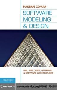
Figure 1: Process life cycle with associated tools
The life cycle of our process models is described by Figure 1, based on [15]: (1) Process meta-modeling defines fundamental process model language structures using techniques such as XML-Schema or custom domain-specific languages [9]. (2) In the second stage the process is modeled (creating structures e.g. work product milestone associations and content e.g. activity descriptions). This stage is finished with a release of a process, which is delivered for (3) application in projects. A feedback loop is established, which opens the door to (4) continuous 3
process improvement [13]. The tools we are developing are closely aligned to the development process’s life cycle. Implementation Technology. We have made the strategic decision to implement all our tools on the same platform. We chose Microsoft .NET with C# for all our tools. One single implementation technology for all our tools makes integration (relatively) easy. The ability for integration of our software is important because the students developing the software come and go and we have to make sure that their work does not depend on others to complete. Source code as part of a thesis is therefore normally developed in isolation and integrated after completion to create an integrated tool chain that comprises all components for the different stages of the development process life cycle. 2.2. Process Modeling: the Process Development Environment The Process Development Environment (PDE) [25] is a tool for the design of process models. It is based on domain-specific languages (DSL) [9, 3] to (1) describe the concepts of the process that the tool shall support and (2) to generate the development environment for process engineers. PDE provides functionality beyond what standard tools are capable of. In particular, it supports process model families or process lines [21] and offers a couple of custom views that should help the process engineer to deal with the complexity of process models. Context. The design of a comprehensive, flexible, and customizable software development process is a complex task, which requires adequate tool support. Tool-supported process design should include not only modeling capabilities for the process model itself but also the ability to find inconsistencies and to generate feedback to the process engineers similar to the instant feedback provided to programmers by modern IDEs. Inconsistencies in a process model can be inaccurate or missing relationships, which, based on the complexity of the model (model element and dependency structures), can be difficult to find and, if not found, can have fatal consequences at later project stages. The development of PDE was motivated by practical experience gathered in projects with industrial and public service partners where we modified and customized the V-Modell XT standard2 . The standard tools coming along with the V-Modell XT make modification and customization work cumbersome as those tools provide no visual representation of the higher-level model structures one would normally want to work with, nor is there any support for finding inconsistencies. Errors are communicated in a cryptic manner, if at all, with the error messages typically saying not much more than “Element is Null”. As the XML-model of the V-Modell XT contains a huge number of elements and relations, locating errors and finding their source is hard and time-consuming. PDE was therefore developed for our own convenience with a strong focus on the V-Modell XT. The reliance on a DSL allows us to implement constraints and validation rules into the tool. In addition to the original V-Modell XT version we have for example developed a variant for the proprietary development process of T-Systems. We are using this variant of PDE in a currently ongoing cooperation with T-Systems. 2 The V-Modell XT [6, 7] is the German standard development process model for IT-projects in the public service area. The meta-model [23] is implemented using a XML-schema.
4
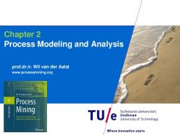
Overview. PDE [25, 26] uses the Microsoft DSL tools [3]. The graphical modeling application for the process engineer is generated from the DSL description of the process model. In general, the application is inspired by well known integrated development environments (IDE) for programming but with respect to process engineers’ special needs. PDE provides a number of key features, such as: • Language-specific validation including design time feedback. • Multiple, language-specific graphical views (language-integrated or plugins). • Plugin interface for additional functionality or graphical views. Architecture. PDE’s architecture [25] basically consists of a family of (meta-)models that are implemented by DSLs as shown in Figure 2. The core model of PDE is the Language MetaModel that describes the domain of software development processes, used to specify the Domain Meta-Model, which is the representation of a concrete (process meta-) model (e.g. SPEM). The domain meta-model’s structure is further used to automatically generate the Domain Model as an instance of the domain meta-model for integration with the Tool Framework. The tool framework is an extensible framework used to visualize and modify the domain model. A DSL created with PDE can host multiple view such as model trees, property grids, graphical designer surfaces or error lists (see Figure 4). Language DSL
Domain DSL Tool Framework
Language Meta-Model
instance of
Domain Meta-Model
View Model
Domain Model
Serialization Validation
Figure 2: DSL Model Family for Process Modeling
Because of the multi-layered architecture with each DSL serving a specific purpose, the implementation of a new process model requires a couple of steps shown in Figure 3: 1. 2. 3. 4.
Specification of the domain meta-model. Generation of the domain model and integration into the tool framework. Applying optional extensions. Building the editor.
The first step is done using the Language DSL Designer, which is a Microsoft Visual Studio extension. If the meta-model of the process is already explicitly written down, this step means to translate the meta-model of the process to the domain meta-model of PDE. In the case of the V-Modell XT, it meant to translate the V-Modell XT’s XML schema definition to the domain meta-model. The second step generates code from the domain meta-model using T4 templates [22]. The generated code can either be used as is or it can be extended – for example with custom validation rules or extensions (step 3). The “language engineer” can decide on the degree of modeling and which extensions will be available to the user. It is possible for instance to implement validation using functional programming languages such as F# instead of modeling a 5
Language DSL 1
Domain DSL
3 Customize
2 Implement a Meta-Model
Transform
WPF Editor (Application)
4 Compile
3
Design & Model Process
Extend Result(s): - domain meta-model
Input(s): - domain meta-model - tool framework
Result(s): - domain model - view model(s)
Result(s): - process model - PDE editor
Figure 3: Concept of developing DSLs with PDE
constraint (due to the ability of the .NET platform to mix several languages). An example of a coded validation rule is a checking algorithm for a graph being free of cycles. A plugin for PDE can can be basic and only define additional functionality or it can provide custom views and editors that are integrated in the PDE main application. After customization and extension, PDE can be built in step 4. This results in the PDE editor application (in Figure 4) for the specified model. Research Questions. PDE is a fully functional application with functionality already going beyond the possibilities of standard tools. Yet, there is plenty of room for further work: Currently, validation constraints are specific to the process model. It would simplify the development of variants for new process models, if validation rules defined in a generic validation language could be reused across models. The same observation is true for serialization: currently, serialization rules have to be specified for each element individually. Another aspect is that it may be useful to combine several models into a larger model. A process engineer may then develop process components and assemble those to the overall process (similar to method libraries in the Eclipse Process Framework [4]). We have yet to gather practical experience on how to deal with model evolution and how it impacts the DSL-based generated working environment. Implementation Statistics. As of June 2010 PDE had a code size of 40 KLOC. Additional 320 KLOC are generated by the T4 templates from the DSLs, adding up to a total code size of 360 KLOC. The readability of the generated portions largely depends on how well the domain model is modeled. If meaningful element names are chosen for the model, the associated source code is human-readable. However, generated and custom code are strictly separated through .NET’s mechanism of partial classes, so a developer usually does not have to bother with the generated code other than for debugging of T4 templates. 2.3. Process Enactment: The Process Enactment Tool Framework The Process Enactment Tool Framework (PET, [17]) is a process transformation framework that bridges the gap between the defined process and project execution. It provides a generic process intermediate model, which arbitrary processes can be mapped onto and which transformed data can be extracted from. PET applies ideas and concepts of model-driven design & development to process enactment. The input to PET is a machine-readable process description (data model); its output side is usually a process-aware tool that provides some kind of process support to users during project execution. PET thus makes a contribution to the enactment of processes. 6
Figure 4: V-Modell XT DSL
Context. Tools can be helpful with regards to acceptance and enforcement of a software development process by providing assistance and automation [16]. Certain tasks prescribed by a process can be automated – relieving the team of repetitive process-related work. Many tools provide rich automation and assistance capabilities that can be used to make the process transparent to users (where adequate). Examples for such tools are Microsoft Team Foundation Server [18], Microsoft SharePoint [27] and IBM Rational Jazz3 . The challenge is to enable these tools to access development process data and interdependencies to support users in their work relieving them of “process-only” tasks. A process defines a common terminology and thus is a medium for communication in a project. With regard to tool chains (integrated and loosely coupled ones) it is therefore essential that all tools “talk” the same process. Because different tools focus on different aspects of the overall development process, a challenge is to extract from the process model exactly the information relevant for a particular tool in a consistent matter, yet ensuring that exchange between tools/tasks is possible.
3 http://jazz.net/
7
Overview. The feature distinguishing PET from other transformation frameworks is that it decouples the tasks process parsing and output data generation by design. Plugins that read process models are called process providers, whereas tool data-generating plugins are named tool providers. Through this separation, it is possible to use the same process model parsing logic to create input data for different output data generators. Consequently, one output generation logic works for any process. Between the input process model and the output generator, PET introduces a generic meta-model that process models are mapped onto. This so-called intermediate/core meta-model contains common process elements, such as roles, work products, activities, milestones including their semantics and their interrelations. The intermediate meta-model was not designed to accommodate every possible element of process models but as a small common subset of process models. Thus, not every construct of a process may be mappable onto the intermediate meta-model. However, the elements it does define are sufficient for process enactment using tools (the main use case for PET). At the time of this writing PET process providers were implemented for: • V-Modell XT 1.3. • SPEM-based processes (currently under development). Tool providers exist to generate: • Process templates for Microsoft’s Team Foundation Server 2008/2010. • Project portals including document templates for SharePoint Portal Server. • Word 2007/2010 document templates in the Office Open XML (.docx) format. Architecture. The architecture of PET [17] is shown in Figure 5. The framework’s architecture contains PET’s core, process providers, tool providers, and an application frame. PET Model and Components
Workflow Engine «use»
Runtime
PET Core (incl. intermediate model)
GUI-Frame «use»
«use»
Application Frame «use»
«use»
Process Plugin Tool Plugin
«use» «use»
V-Modell XT Meta-Model
SPEM
Team Foundation Server
Sharepoint Server
Word docx Templates
Figure 5: Schema of PET’s architecture.
The PET core is at the center of the framework. It contains the interfaces and methods that are used by all process and tool providers as well as by the application frame. The core includes 8
the intermediate/core model, the process- and tool provider interfaces, and the conversion process interface, which gives plugins some control over the transformation steps. Process providers bridge the gap between the input process and the intermediate model. They are responsible for reading a process model and mapping it onto the generic PET process model, while preserving the process’ semantics. Tool providers are responsible for the generation of the output data of the process transformation. Their input is the intermediate model, which was initialized before. Because parsing and (code) generation is encapsulated in self-contained provider plugins, a plugin developer can use arbitrary frameworks for parsing/generation. Another central component is the application frame. It orchestrates the execution of the different transformation steps displayed in Figure 6. The graphical user interface allowing the selection of the different provider plugins and a couple of infrastructure components such as plugin configuration serialization and deserialization are also part of the application frame. Application Frame integrated Process dynamically loaded Show Welcome Page
Select Process Provider Controlled by Process Provider Plugins
dynamically loaded Configure Process Provider
Select Tool Provider
Configure Tool Provider
Execute Transformation
Store/Exit Transformation
Controlled by Tool Provider Plugins
Figure 6: PET transformation workflow.
Research Questions. As already mentioned, there are two process providers available for PET (V-Modell XT [6] and SPEM [19]) at the moment. It would be interesting if other process models can be processed in equal manner. As mentioned above, the intermediate meta-model contains common elements of process models. Special elements of a process model possibly would get lost in the mapping process. We have to gather further experience with regard to extensibility of the intermediate model. Already, it is possible for process providers to add “custom” elements and non-standard semantics to the intermediate model. The downside of this approach is that tool providers will not understand the semantics of these elements by default and probably ignore them (a problem well known in the UML/MOF world [20, 1, 10, 11]). Allowing process providers to extend the intermediate model limits the set of tool providers that can be used with a certain process provider. The associated research question is how this can be done without contradicting PET’s general transformation approach. PET’s current architecture assumes the existence of exactly one process- and one tool provider per transformation. An idea we have yet to realize is the chaining of multiple tool providers, using the previously created output as input data. A scenario may be for example to first generate work product templates and then upload these to a SharePoint portal that will be used as project workspace. Implementation Statistics. The PET code base has a size of 2.5 KLOC. The current version is around 15 months old. It is the result of an effort to combine a couple of independent transformation/generation tools that we had developed since 2005. 2.4. Further Tools The previous sections presented the main development lines – tools motivated by practice and in a state and quality near “real” products. Besides those, we developed small tools for (1) solving individual problems of our projects and (2) experimental tools. 9
In the first category we have add-ons supporting specific tasks during process design and implementation. Examples include assessing constructive process model conformance. Currently, it is available as early prototype, which will be integrated in PDE to support process engineers. We also have available specialized build tools supporting delivery of a customized process. In the second category, we are currently working on an experimental work item tracking system that supports process design and execution, flexible work item structures, and arbitrary associations between elements [24]. Additionally, starting from this project, we investigate project runtime support. We are developing and testing assistance systems in the experimental work item environment to prepare for integration into PET. We do for example have an early version of a plug-in for Microsoft Word that provides additional functionality for PET-generated document templates. 3. Challenges in Academic Tool Development & Lessons Learned
X X
(M9) Lectures
X
(M8) Strategy
X
X X X
(M6) One platform
X
(M7) Promotion
X
X
(M5) Central repository
X X X
(M4) Project responsibility
X
(M3) Publications
Finding students (C1) Student fluctuation (C2) Kind of student work (C3) Qualification of students (C4) Result quality (C5) Goal congruency (C6) Development roadmap (C7) Technology (C8)
(M2) Payment
(M1) Advertisement
In Section 1, we have briefly highlighted the special challenges that we are facing in academic tool development. To handle these challenges (discussed in detail in Section 3.1), we have found over time and through (sometimes negative) experience a couple of best practices, discussed in detail in Section 3.2. To provide an overview, Table 1 roughly puts in relation the challenges that we face and countermeasures we are applying.
X
X X X
X
Table 1: Challenges and strategies
3.1. Challenges The greatest influencing factor on our tool development is that we do not have a permanent development staff and are mostly relying on students for the development work. In some way or the other, most of the challenges are related to this factor: 10
(C1) It is not easy to find students. As members of a large faculty with 22 chairs, that we compete for the best students. The subjects of lectures, practical courses, and theses we are offering may look unattractive to many students compared to other offerings. Courses such as “Game development for the iPhone” will always have a greater appeal to students. (C2) The duration of student theses is limited. The duration of a normal student thesis is limited to 6 months. That time frame imposes a natural boundary for the size of the work package to be worked on by the student. Furthermore, the relatively short time that we normally have with one student implies a high turnover in our student team. (C3) Kind of student work. A topic for a student thesis must contain a certain amount of conceptual and theoretical work. We cannot formulate a thesis topic that only contains programming work. Some of the features that we would like to see implemented are mostly programming work. For such features to be realized, we either have to pick special course formats with less emphasis on theoretical work than a Master’s thesis or we have to tailor the topic so that it does meet the difficulty requirements. (C4) Qualification and suitability of students. It is hard to judge beforehand how capable and suited a student is. Furthermore it is very difficult to not accept a student interested in a subject – firstly because we have to be thankful for every student (see C1) and secondly because of university regulations (we do not have legal means to turn down a student). (C5) Result quality & integration maturity. There is a large variation in the quality of the outcomes of students’ works. Some results we can use and incorporate into our tools – some we cannot. If the outcomes meet the expectations, there is usually some integration work left to be done. In the case of students struggling with our expectations, we often have more effort with supervision than for other students while the outcome may turn out not to be usable. (C6) Differing goals of researchers & students. Researchers and students do not necessarily have congruent goals. Researchers want to check and validate their scientific ideas and to establish good relations with industrial partners for possible funding. Students usually want to get good marks with the least effort. Additionally – as studying is expensive – many students are interested in a job. Taking a job in industry is often more attractive as the payment usually higher and there are clear objectives. (C7) Development Roadmap. It is almost impossible to establish a meaningful development roadmap as we often do not know if, when, and for how long students will be available. Scheduling detailed work packages only works if students are available. Any project plan is meaningless without development resources that we can reliably plan with. If we find a student willing to work in our team, it does depend to some extent on the preferences of the student which work package he or she takes over. (C8) Implementation Technology. For historical reasons we are using .NET for all our tools (Section 2). In the introductory lectures at our faculty, Java is used to teach students programming. Many students do not have the motivation to learn additional platforms. The chosen technology limits the number of students we can consider for our work.
11
3.2. Measures We have established measures to face the challenges listed above. In the following we describe how we handle the challenges. For each of the measures, we indicate in brackets the addressed challenge(s). (M1) Advertisement of courses and seminars. We are still looking for the best ways to recruit students (C1). All our open student thesis topics, courses and seminars are held in a database on the chair’s servers. The database is accessible through the chair’s Web site and the theses are also displayed on the individual researchers’ Web sites. Other chairs have similar facilities. In addition, courses and seminars are managed in a faculty-wide database, so there is one central site where students can find and pick their courses. We will soon move our thesis offerings to a faculty-wide database, too. Some thesis topics do not find interested students for a couple of years – sometimes until the topics do no longer fit our own strategy. Our hope is that this move will result in a greater visibility of our “job offerings”. Another measure that we are experimenting with is the advertisement of courses using offline media, especially posters. For the future we are considering to post an announcement for our courses in a popular student Web forum. (M2) Payment for students. A central goal is to reduce student turnover (C1, C2) and to create longer-term relationships with students. We are employing students that have proven their capabilities to keep them in the team beyond the regular theses runtime. Contrary to an employment in industry where the students may get paid better, the students remain very flexible when working for the research group. Work can normally be done at home and we do not require fixed working times. We are also making sure that the work does not interfere with other obligations such as learning for an exam (C6). Another advantage is that we can assign “normal” programming work to employed students – something we cannot in the context of theses (C3). (M3) Publications for students. In addition to payment, we are trying to give further incentives (C2) by publishing interesting results of student works – for example from a thesis, as shown in [26] – together with the students. Some benefits for the students are (1) the publications can be helpful if the student eventually pursues an academic career, (2) it is a good exercise for the final master’s thesis, (3) the students get insight and background information on the work subjects (C6). (M4) Project responsibility for students. With the tools and the code base we have built over the years, it is the exception that a completely new and isolated tool is developed in student projects. Most of the practical courses or theses that we are offering deal with the implementation of new features for existing tools. The strategy and requirements come from the research staff. However, the responsibility for the code itself is usually with an employed student (C2, C6) of the core student team (see Section 4). These students are also responsible for much of the integration work (C5, C7). (M5) One central repository. We have one subversion repository. The research staff and the students all work on the same repository. Students even use the repository to manage the LATEX source files of their theses. The central repository helps to create an atmosphere of openness. More importantly, it has grown to a huge knowledge base over time. The source code, LATEX sources and other documents can be used by everybody looking for examples or best practices (C5). One repository for all our students and for ourselves creates a certain amount of management overhead and is not common practice at our faculty. Most researchers and students maintain their own, private repositories. 12
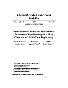
(M6) One technological platform. We have made the strategic decision to only use C# and .NET as technological platform. Whenever a problem involves programming work, it must be done in C#. This is one of the few non-negotiable preconditions before we accept a student. The result of the strategy is that (1) we are able to provide detailed programming support to students (C4), (2) we are able to provide students with the necessary tools, for example Visual Studio, (3) we are able, to understand every detail of the outcomes, (4) Students can understand each others code and profit from each other. If there is a lack of resources in one tool project, it can be compensated by other members, and (5) we can integrate outcomes of different student projects into a larger software (C5). Some portions of the source code were originally developed to solve a particular problem and only much later assembled to form an integrated solution. (M7) Active promotion of our software. We are actively looking for collaboration partners to use our tools and to drive development forward. (1) The tools are used in industrial cooperation projects and often demonstrated and showcased to interested parties. (2) Large parts of our code are put up on CodePlex4 . (3) We work together with another university where we act as client and a student team at the other university was building a component for PET in a practical course (C7). (M8) Flexible and “opportunistic” strategy. As mentioned above, one challenge in academic tool development is that we cannot reliably plan our development resources and we can judge the quality of the outcomes of students’ works only after the fact. Our product strategy is therefore very flexible and opportunity-driven (C7). Some of the tools have not been build with a clear roadmap in mind but only after, for example, a student thesis was completed (C6). The opposite is also true where we had high expectations for a thesis but the outcomes were not usable and were not integrated into our code base. Another factor influencing our tool strategy is that we have to quickly respond to the requirements coming from our (funding) industrial partners. (M9) Lectures. With regards to our chosen implementation technology one can roughly distinguish two types of students: Some students already have knowledge with .NET and are interested in the platform. Because Java is the de-facto standard in teaching at our faculty, such students are rare. There are also students who show interest in the platform but do not have any experience with it (C8). To make students familiar with .NET and to identify the interested students we are offering specialized lectures – for example a seminar about the basics of C#. Summary Summing up, we are trying to tackle the challenges in academic tool development by creating a positive working environment for students that lasts longer than just for the time of a practical course or thesis. Because the tool development is driven by industrial cooperations or our own research, the students find challenging, relevant, state-of-the-art and “real” problems to work on. Figure 7 shows the number and distribution of student works, their types and the associated tool projects. To give an idea for the topics students work on, we refer to [24] and [25]. As can be seen in the diagram “Projects”, PET is the oldest and still most active project. Especially with regards to project execution support, we are developing many new prototypes in the context of PET. The diagram “Types” shows the distribution of different kinds of student works. It (still) 4 http://www.codeplex.com
13
Project/Work Types Distribution
Projects
Project
BT
MT
DT
PC
Sum
PET
1
3
2
3
9
PDE
1
2
0
0
3
Other
1
0
1
2
4
Sum
3
5
3
5
16
Other: 4 PDE: 3
Types
BT: Bachelor's Thesis MT: Master's Thesis DT: Diploma Thesis PC: Practical Course
PET: 9
BT: 3 PC: 5 MT: 5 DT: 3
Figure 7: Distribution of projects and students’ works
shows a high number of Diploma theses, which will decrease due to the Bologna Process5 [5]. This development is actually an advantage for us because a student joining our group for his Bachelor’s thesis usually stays at university for another two years to earn his Master’s degree. Such students are candidates for employment in our group. If we get to know a student while he completes his Diploma thesis, it is too late to think about employment. Most of those candidates are leaving university soon after. Measures that worked. We have observed that a new lecture is not very popular when offered for the first time. Offering the same lecture periodically, we notice increasing visibility and popularity. As an example, we are offering a seminar about object-oriented programming with C# where we have twice the number of participants in the current winter term 2010 compared to the previous year. Another example is a practical course that we are offering every semester where we have a stable number of participants. Measures that did not work. For some courses, we have designed posters that we put up near the entrances to our faculty building. The first time we tried posters, these did not seem to have any effect. We had zero students for the advertised course. We are currently trying posters again for two courses and have yet to see if they make a difference to find students. So far, it appears that again the posters have no effect. If we are getting feedback from students about our lecture offerings, it is usually from students coming to us because they are interested. Much more interesting of course would be why a seminar or practical course did not generate the desired interest. We are however not aware of a working method to collect feedback from students not interested in our offerings. 4. Organization & Development Process In this section we describe how our group is organized today. The organization has steadily evolved over the last couple of years and is basically a result of our experiences outlined in 5 The Bologna Process harmonizes the European graduation system. In Germany, the Diploma degree is getting replaced by Bachelor’s and Master’s degrees.
14
Section 3. It also reflects the fact that as members of a university, most of our funding comes from collaborations with industrial partners. Not just for the tools, the partners take on the role of the customers. How they are involved and how we work together internally with researchers and students is outlined in the following. Organization. The rough structure of our research group is displayed in Figure 8. We are orgaExternal Researchers
Students (temporary)
Student Staff (Core Team) Research Staff (Core Team)
Projects and external Partnern
(supervising all developments) Common Repository partial access
Project Project Project
Figure 8: Organization of the research group
nized in four areas: (1) the core team consists of the employed researchers (including ourselves) and students. The research staff owns the common repository, supervises the students and coordinates projects and tool development. Each of the employed students is responsible for one tool and coordinates integration, especially of the parts developed by temporary students. (2) External researchers are people that do their research at our chair but are not on the chair’s payroll. They are available only temporarily and are generally not as much involved as the employed staff – they do not for example have teaching obligations. (3) Temporary working students – e.g. working on their theses – are also embedded in the research group. External researches as well as temporary students have partial access to the repository. (4) External partners participate according to their projects’ context, mainly by consuming tools. A central component is the common repository. All data of the group is stored there. Everybody has complete access, except for a couple of directories that contain sensitive/confidential data, e.g. grades or financial calculations. For legal and privacy reasons we cannot give access to this data to all users of the repository. These areas are only open for the employed research staff. Processes. Our development process varies depending on the tool project. If it is (1) an experimental (component of a) tool, then the development is self-organized by the developing student. If it is (2) a tool that is mature for release or already released, an organized development process is established in the research group as shown in Figure 9. In general two aspects must be mentioned: At first the continuous development in the research group and furthermore developments and publications to the community. For the internal development, a team is constituted, which consist of at least two researchers (core team), one student (core team, senior student), and additional temporary students. External researchers and partners contribute where appropriate. In a tool project, the senior student is responsible for the development tasks in the project (coordination, integration, test). The development is planned using simple feature lists – if a tool is already 15
Research Group
Team Tool Project Open Source Community
Team Tool Project
Issues, Bugs etc.
Planning and Strategy Coordination of OSS activities and projects
Tool Development Process Features, Architecture Internal Test
Coordination of industrial projects Tool Release Coordination of students' theses
Issues, Bugs etc.
Feedback
Open Source Project (Launch/Update)
Application in Project with Partners
Figure 9: The tool development process of the research group
published to the Open Source community, the facilities of the Open Source community site – for example issue trackers – are used. Development starts with selecting features, defining the goals, the design of the architecture, and a rough schedule. Once the first implementation is available, the internal tests start. Internal test does not only mean running test cases but also checking the implementation against the requirements and improving the source code. Having finished the internal tests, a milestone for a (new) release is reached. At this point, two activities are performed: (1) the internal release is built and stored as a baseline in the common repository; (2) the tested code and release (executables, documentation, etc.) are published at the Open Source site. Furthermore, the published sources and tools are provided to the partners for their work. In the meantime feedback loops are established. We collect feedback from both the community and the partners. In combination with the original feature list, we plan new releases. At this point it is important to know that the development is still driven by the research group – not by the community. The community sponsors new or updated components, but testing, integration in a release and so on is controlled by the group. The reason is quite simple: we involve temporary students who obtain their grades by taking part in our tool development. To align the strategy and the students’ goals, we must have control the development. This strategy creates additional effort, but is necessary to hold the working environment stable for the students.
16
5. Transfer Strategy Academic tools need validation by practice. As most of our developments are motivated by practical problems, we always look for cooperations in industry and the research area to apply the tools. This section gives an overview over our transfer strategy. Academic Research & Projects. The first part of the transfer strategy is in the academic area. We (1) use our tools for teaching. Lectures and seminars for instance include PDE besides standard environments such as the Eclipse Process Framework [4]. Practical student works as well as theses address PET. We (2) work together with other universities, e.g., the University of Applied Sciences in Rosenheim, to advance the tools. Furthermore, our tools are a matter of current research. We (3) use PDE and PET for modeling and proof of concepts developed in Ph.D. theses. Industrial Cooperation Projects. PET has been in use for the generation of work product templates in cooperation projects for example with the Federal Network Agency and Siemens. The Federal Network Agency’s internal software developers are using Microsoft Team Foundation Server. We are currently working on a process enactment strategy with the Agency involving their TFS and PET. PDE is relatively new and early versions are delivered to selected partners. First cooperations are already established, e.g., with T-Systems where PDE is used to model the proprietary development process. Within cooperation projects, we are using the tools ourselves, to gather experiences before providing the tools to partners. For example as PDE now provides the required minimum of stability and enough features for efficient work, it replaces other design tools such as EPF or the V-Modell XT reference editor [6]. Open Source Strategy. To reach a broad audience, we make our tools accessible to the Open Source community. Due to our .NET framework-centered development activities we publish and manage our projects6 on CodePlex, Microsoft’s Open Source project hosting site. Our Open Source strategy offers advantages for both the tools’ users and our team. The users get to review the program’s functionality and quality before using it in their projects. Through the projects’ openness and availability, we hope for a growing user base that reports bugs and inspires new features, which helps us improve the tools. As described in Section 2, our tools are specialized for a specific domain. They are no massmarket consumer tools and require a lot of know-how. The industrial cooperation or funded research projects do usually not contain a budget for tool development. As a university we are “selling” know-how – our tools are something that we bring in for free. As such, we do not lose anything by publishing the source code. 6. Conclusion For our specialized work on software development processes, we have a constant demand for tool support. Many of the requirements that we have or simply ideas that we want to try out are not covered by existing tools. We are therefore developing many tools ourselves. Several mature tools have been developed over time. Developing the tools was possible only by finding an 6 Usually
we publish the tools under the Apache 2.0 license.
17
organization structure that respects the particular concerns (listed in Section 3) of the academic environment: we are facing some specific challenges developing tools because there usually is no budget for software development and because we do not have a dedicated development staff. Most of the development work is done by students, for example in the context of a Bachelor’s or Master’s thesis. We have taken certain measures and found out things that worked and things that did not with regards to our kind of “development team”. Discussion. Experiments such as using offline media to advertise courses have had very limited success so far. Whether moving all our thesis offerings to a central database will make a difference has yet to be seen. A measure that worked is the employment of students to build a stable team. If the students are integrated in the team, their performance often goes beyond the curriculum’s requirements. So, if for example a Master’s thesis is calculated with an effort of 6 man-months, the real amount of work done by the student is often two to three times as much (estimated based on the size and volume of the deliveries). However, this requires a special, highly self-motivated, open-minded and creative kind of students. It is not possible to employ every student due to project, administration, and financial limitations. The selection process for students’ employment must respect long-term perspectives and enough time for learning for the students as well as for the researchers’ goals. Referring to the challenges that we are facing (Section 3), our experiences lead to further questions: • Learning vs. working: Students need time for their studies. We have established a structure for our employed students that enables them to control their working style. For students that work with us only temporarily, we set clearer goals – normally aligned to the curriculum’s requirements. We currently have only a handful of lecture formats to choose from. A question we do not have an answer to is what adequate lecture format is for our requirements. • Lecture format: Currently we only have lectures, seminars, and practical courses (1) to advertise and (2) to provide students with work. Are there other forms of teaching possible that make our area of work more attractive to students? • Cooperation style: For the core team (shown in Figure 8), we have a flat organization and cooperation style where each member has certain responsibilities. The flat hierarchy creates an open working atmosphere but limits the size of the team. This style works good for us but implies a risk: It works as long as the team is relative stable, as a high turnover in the student staff results in management effort (training, repository, contracts). What other organization styles are possible? At the same time, budgets for tool development (including students’ payments) are rare. So, we are forced also to include non-employed students with the effects stated in Section 3. The availability of non-employed students is almost impossible to plan, which destabilizes our planning and strategy. Relevant questions arise from this situation are: • Alternative transfer strategies: We selected Open Source as basic concept for transferring our tools. In combination with research and consulting projects, we attract funding but must align the strategy according to the current projects. What are other strategies for a transfer? Are there alternatives to a spin-off? 18
• Planning: Planning the development depends on project situations and resources. While we do have a long-term “product strategy”, it is hard to set milestones and completion dates (see Section 3). What other styles of project-independent planning exist? • Target achievement: The achievement of the objectives is also closely coupled with the current projects. How well is the target achievement in other than our situations? What about the quality of the resulting tools? The tools that have been developed in our group are evidence enough that the organization of our group and the measures we are taking to deal with the special challenges of the academic environment work in principle. The organization, the measures and the development process that we have outlined in Section 4 are the result of an ongoing learning process. Especially the development process we have not designed from scratch but refined based on the lessons learned. It has now stabilized to a point where for the first time we can consider to formalize it. Such formalization would allow us to apply PDE and PET more extensively for our own group. Currently we have a relatively stable team that works together efficiently. However, some of our core team students have stayed with us for a couple of years and will finish studies soon. They are still the first generation of students that we have worked with in the described way. We will see how robust our organization is when we bring up a new generation. We are offering several seminars and lectures to get in touch with potential candidates in the current winter term 2010. References [1] Amelunxen, C., R¨otschke, T., Sch¨urr, A., 9 2005. Graph transformations with mof 2.0. In: Giese, H., Z¨undorf, A. (Eds.), Proc. 3rd International Fujaba Days 2005. Vol. tr-ri-05-259. Universit¨at Paderborn, pp. 25–31. [2] Beck, K., 2003. Extreme Programming. Addison-Wesley. [3] Cook, S., Jones, G., Kent, S., Wills, A. C., 2007. Domain-Specific Development with Visual Studio DSL Tools. Addison-Wesley. [4] Eclipse Foundation, 2010. Eclipse Process Framework (EPF). Online, http://www.eclipse.org/epf. [5] European Commission, 2010. Focus on Higher Education in Europe 2010 – The Impact of the Bologna Process. Resource page: http://eacea.ec.europa.eu/education/eurydice/documents/thematic reports/122EN.pdf. [6] Federal Ministery of the Interior, 2010. V-Modell XT Online Portal. Online. URL http://www.v-modell-xt.de/ [7] Friedrich, J., Hammerschall, U., Kuhrmann, M., Sihling, M., 2009. Das V-Modell XT, 2nd Edition. Springer. [8] Goodman, A., 2005. Defining and Deploying Software Processes. Auerbach Publishers Inc. [9] Greenfield, J., Short, K., 2004. Software Factories. No. ISBN: 978-0471202844. Wiley & Sons. [10] Hermannsd¨orfer, M., 2010. Migrating UML Activity Models with COPE. In: TTC 2010. [11] Hermannsd¨orfer, M., Ratiu, D., 2009. Limitations of Automating Model Migration in Response to Metamodel Adaptation. In: Proceedings of Joint ModSE-MCCM Workshop on Models and Evolution. [12] Jones, L. G., Soule, A. L., 2002. Software Process Improvement and Product Line Practice: Capability Maturity Model Integration (CMMI) and the Framework for Software Product Line Practice. Tech. Rep. CMU/SEI-2002TN-012, Software Engineering Institute. [13] Kneuper, R., 2008. CMMI: Improving Software and Systems Development Processes Using Capability Maturity Model Integration (CMMI-Dev), 1st Edition. No. ISBN: 978-3898643733. Rocky Nook. [14] Kruchten, P., 2003. The Rational Unified Process: An Introduction, 3rd Edition. Addison-Wesley Longman. [15] Kuhrmann, M., 2008. Konstruktion modularer Vorgehensmodelle. Ph.D. thesis, Technische Universit¨at M¨unchen. [16] Kuhrmann, M., Kalus, G., Chroust, G., 2009. Tool-Support for Software Development Process. No. ISBN: 978-160556-856-7 in Business Science Reference. IGI Global, Ch. 11, pp. 213–231. [17] Kuhrmann, M., Kalus, G., Then, M., 2010. Flexible Process-Tool-Integration. Research Report TUM I-1005, Technische Universit¨at M¨unchen. [18] Microsoft Corporation (Ed.), 2007. Team Development with Visual Studio Team Foundation Server. No. ISBN-13: 978-0735625716. Microsoft Press.
19
[19] OMG, 2005. Software process engineering metamodel specification. Tech. rep., Object Management Group. URL http://www.omg.org/technology/documents/formal/spem.htm [20] OMG, 2006. Meta object facility (mof) core specification –version 2.0. Meta object facility (mof) core specification, Object Management Group. [21] Rombach, D., 2005. Integrated Software Process and Product Lines. In: Li, M., Boehm, B., Osterweil, L. J. (Eds.), Unifying the Software Process Spectrum, International Software Process Workshop, SPW 2005, Beijing, China, May 25-27. Lecture Notes in Computer Science. Springer, pp. 83–90. [22] Sych, O., 2007. T4: Text template transformation toolkit. http://www.olegsych.com/2007/12/ text-templatetransformation-toolkit/. [23] Ternit´e, T., Kuhrmann, M., 2009. Das V-Modell XT 1.3 Metamodell. Research Report TUM-I0905, Technische Universit¨at M¨unchen. [24] Then, M., Februar 2010. Design of an intelligentwork item tracking system. Bachelor Thesis. [25] Wachtel, E., 2010. Design of a Domain Specific Language for designing of process models based on the V-Modell XT Metamodell. Master’s thesis, Technische Universit¨at M¨unchen. [26] Wachtel, E., Kuhrmann, M., Kalus, G., 2009. A Domain Specific Language for Project Execution Models. In: Fischer, S., Maehle, E., Reischuk, R. (Eds.), 39th Annual Conference of the German Computer Society. Lecture Notes in Informatics (LNI). pp. 2986–3000. [27] Webb, J., 2007. Essential SharePoint 2007: A Practical Guide for Users, Administrators and Developers, 2nd Edition. O’Reilly Media, iSBN: 978-0596514075.
20