ployment stages of enterprise distributed computing systems life cycle. This paper focuses on ... a small but powerful set of enterprise modelling concepts.
P ro c es s es, Roles, an d Even t s: U M L C o n cep t s f or En t erp rise Arch it ect u re Alistair Barros, Keith Duddy, Michael Lawley, Zoran Milosevic, Kerry Raymond, Andrew Wood CRC for Enterprise Distributed Systems Technology (DSTC) University of Queensland, Brisbane, Queensland 4072, Australia {abarros, dud, lawley, zoran, kerry, woody}@dstc.edu.au Abstract. This paper presents an integrated approach for modelling enterprise architectures using UML. To satisfy a need for a wide range of modelling choices, we provide a rich set of process-based and role-based modelling concepts, together with a flexible way of associating business events with business processes and roles. Our approach enriches Unified Modelling Language (UML) to support the requirements of enterprise distributed object computing (EDOC) systems and is currently being considered by the Object Management Group (OMG) for standardisation.
1
Introduction
As the maturing distributed object and component technology becomes more widely deployed in enterprises, there is an increasing demand for a set of tools and methodologies to support forward and reverse engineering of enterprise computing systems. These tools and methodologies are needed to: i) facilitate the building of enterprise computing systems that closely follow the structure, dynamics and policies of enterprises, and ii) allow for faster modifications of enterprise computing systems according to changing requirements of businesses. Such tools and methodologies need to support the use of object-oriented approaches across the analysis, design, implementation and deployment stages of enterprise distributed computing systems life cycle. This paper focuses on providing a better support for the analysis phase in the life cycle of enterprise distributed computing systems. Our approach is based on the introduction of modelling concepts that represent dynamic, structural and policy aspects of enterprises. We provide support for enterprise concepts such as business process, business roles, business entities, and business events. We allow for flexible integration of these to closely model the operations of enterprises. The goals for our work are to provide: • a small but powerful set of enterprise modelling concepts • an expressive graphical notation • a basis for automatic generation of component-based enterprise systems (e.g. using CCM [1], EJB [2], COM [3]). The application of modelling at the enterprise level is not new when one surveys the work done in requirements engineering [4], integrated CASE [5] and business process (workflow) automation [6]. However, there is a need for a more generic and integrated approach (e.g. process and policy versus procurement and service level agreement) with a broader technology target (inclusive of workflow management systems). Our immediate focus at present is on applying this approach to extend the modelling capability of
UML [7] and is in part influenced by the recent OMG Request for Proposal (RFP) for Enterprise Distributed Object Computing (EDOC) [8]. Therefore, in this paper we will demonstrate how our approach for modelling EDOC systems can be related to the existing version of Unified Modelling Language (UML). The content of this paper is structured as follows. Section 2 motivates the paper by presenting key modelling concepts used in our EDOC modelling approach. Sections 3, 4, and 5 give an overview of our models for business processes, business entities, and business events. Section 6 concludes and outlines our future work plans. Note that the full specification of our EDOC models is given in our EDOC submission to the OMG [9]. The full specification provides a UML model showing the relationship between all the concepts, and a detailed description of the rules and semantics applicable to each concept. It also provides a full description of the graphical notation, and presents a substantive example based on the work of a conference programme committee. Mappings of our EDOC models to various CORBA technologies are also presented to illustrate the generic nature of our proposal. We expect our EDOC models will continue to evolve as part of the OMG adoption process, including harmonisation with other parallel developments within the OMG’s Analysis and Design Task Force, e.g. the forthcoming UML v2.0.
2
Key EDOC Concepts and relation to UML
This section introduces key models we use to describe various aspects of Enterprise Distributed Object Computing (EDOC) systems. These models provide direct support for business processes, business roles, business entities, and business events and are well suited to extend UML to meet EDOC requirements, as specified in [8]. In fact, in deriving these models, our starting point was an analysis of how the EDOC requirements stated in this RFP can be met using the existing UML modelling concepts. Because UML is a general modelling language, there are many UML concepts that can be used to support the modelling of EDOC systems. However, we have also found that: • many of the concepts are dispersed across different UML views and it is not easy to establish relationships between them • there is a need for further extensions and refinement of the existing concepts to better meet enterprise requirements; this will further augment the richness of the UML in terms of its computational expressiveness. For example, we needed better support for capturing the coordination semantics of business processes (e.g. explicit support for business events and exceptional situations), semantics of business roles and business rules. The above two points mean that it is not easy for an enterprise modeller to effectively and efficiently use UML 1.3. for modelling systems to support enterprise distributed object computing. Therefore, to provide a set of self-contained concepts suitable for practical enterprise modelling, we have integrated ideas from areas such as workflow systems, requirements engineering, and the ODP Enterprise Language standard [10]. 2.1 Business Perspective to Process Modelling Our approach to modelling business processes is based on our understanding of what are the critical business issues to be addressed when describing processes in the enter-
prise. A business process is represented as a dependency graph of business tasks linked in a specific way to achieve some particular objective. A business process can be control-driven or data-driven, or both, and our model provides a rich semantics for expressions of these task dependencies. Our model also supports the composition of business tasks in a way that is suitable for implementation as off-the-shelf components. In addition, we make provision for an association of business tasks with business roles to execute them. Although our business process model uses concepts found in many workflow systems, nonetheless we view workflow as an IT solution to automating and managing business processes, mostly focusing on the execution semantics. Instead, in our approach, we have attempted to come up with a succinct business process model that encompasses different workflow execution semantics. In addition, we consider business processes in the context of other business determinants, such as business roles, business entities and business events resulting in an emphasis on business semantics over computational semantics. Our submission to the OMG [9] describes a number of alternate mappings from our business process concepts to various CORBA technologies, only one of which uses the OMG’s Workflow Management Facility specification [11]. 2.2 The Duality of Business Processes and Business Roles We believe that business process modelling is only one (though frequent) approach to modelling a business. There are other possible ways of modelling and, in particular, we argue that business role modelling represents an alternative and/or complementary way of modelling the enterprise. This duality of role-based and process-based approaches is also reflected in our paper. In fact, we provide a separation of process-based and role-based modelling concepts as a way of offering different modelling choices. In addition, we separate the notion of business role and business entity, as this separation provides a powerful mechanism for distinguishing between required behaviour and business entities that can satisfy this behaviour. 2.3 Business Events In both, process-based and role-based approaches, it is important to expose business events of significance to the enterprise. These events are associated with the modelling elements that can be their sources or sinks and our approach allows for flexible mapping of business event parameters onto the business process elements as well as business roles. 2.4 Business Processes and their Support in UML It is our view that the modelling of business processes requires the ability to express: • complex dependencies between the individual business tasks (i.e. logical units of work) constituting a business process. Both control dependencies and data dependencies, as well as rich concurrency semantics, must be supported. • representation of several business tasks at one level of abstraction as being a single business task at a higher level of abstraction and precisely defining the relationships between such tasks. This must incorporate the activation and termination semantics for these tasks. • representation of iteration in business tasks
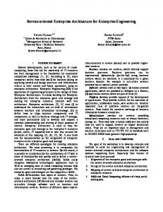
• various time expressions, such as duration of a task and support for expressions of deadlines • support for the detection of unexpected business events that need to be acted upon, i.e. exceptional situations • initiation of specific tasks in response to business events arrival • associations between the specifications of business tasks and business roles that perform these tasks and also those roles that are needed for tasks execution While UML activity diagrams can provide support for most of the above requirements, we have identified a number of difficulties for their use in practical modelling: • Swimlanes are not adequate to represent complex associations of responsibilities to activities (i.e. roles to tasks in our model), and in particular this mechanism does not scale (e.g. how we deal with tens or hundreds of activities) and how we deal with assigning several roles to one activity. • External events cannot be used to start activities except by the intermixing of normal states from UML state machines and activity states from UML activity diagrams, as only the completion event of an activity state (and not an external event) can trigger the transition to another activity state. • According to [12], “Normally, an activity graph assumes that computations proceed without external event-based interruptions (otherwise an ordinary state machine would be preferable).” Hence, most of the states in an activity diagrams are action states or sub-activity states. However, it is also legal to include ordinary states (from state machines) into activity diagrams. This presents the additional modelling problem of distinguishing between those transitions that are triggered by the completion of previous activity state and the external transitions. • Activity graphs support only very simple forms of synchronization and impose a well nesting constraint such that every branch has a corresponding merge and every fork a corresponding join. It is common for a business process to not satisfy such a constraint, to require complex forms of synchronization and, in fact, to not be expressible using an explicit end-of-activity state but instead terminate when ‘there is no work being done, and nothing more to be done’. All of the above suggests that activity diagrams can be used for some business processes - those that include a well-defined sequence of business steps, each of which can be completed with certainty, and without external events involved. In general, business processes require support for more complex concurrency than supported by activity diagrams. For example, one needs a form of unrestricted concurrency that allows the dynamic creation of many parallel chains of execution without requiring that these independent chains need to be joined at a later stage. Thus we believe that business process semantics requires a richer behaviour specification than that provided by UML state machines (the basis for UML activity diagrams). Therefore we derive our business processs model from more fundamental UML model elements: UML::NameSpace, UML::ModelElement, UML::Action and UML::Parameter as illustrated in Figure 1.
Figure 1 Business Process Model
terminates
1..* 0..*
contains
contains
0..*
Terminator Task style : String
Simple Task (abstract)
Invoker Task synchronous : Boolean
0..*
invokes
1
function : String exception_handler : Boolean
Task (abstract)
UML::NameSpace (abstract)
1
3..*
Decision
triggers
Exception
Output Set
Clock
Application Task
1
DataSet (abstract)
contains
Input
1
1
Receive Communication
Multi Task
Output
source
0..*
Data Element (abstract)
Compound Task
contains
0..*
contains
0..*
Send Conmunication
Input Set
contains
UML::Parameter
source
sink
0..*
0..*
0..*
Control Point
realises
Data Flow
Business Process
0..*
0..*
1
sink
0..*
Control Flow
contains
0..*
Flow (abstract)
UML::ModelElement (abstract)
2.5 Business Roles and their Support in UML In terms of business roles, we believe that they should be described as fragments of behaviour of the enterprise - those that can then be fulfilled by specific business entities. The separation of the concepts of business entities and business roles enables the specification of the enterprise in terms of behaviour and not in terms of business entities. This modelling approach provides flexibility in assigning business entities to business roles; one business entity can fill more than one role and one role can be filled by different entities, as long as behaviour of such an entity is compatible with the behaviour of that business role. This allows flexibility in changing the assignments of business entities to business roles as new policy or resource requirements may demand. This is possible because of the way we partition the behaviour of business roles onto business entities. Consequently, we believe that it gives more expressive power to describe business roles in terms of fundamental behaviour, as included in the UML common behaviour package (rather than as a concept within UML collaborations). In fact, we believe that the UML concepts of Action and Action Sequence can be used to define a business role and we derive our definition of a business role from these UML concepts. Such treatment of business roles also provides a basis for flexible assignment of the performers of actions in a dependency graph of business tasks forming a business process. In fact, a business role can be regarded as a collection of actions that are involved in performing one or more business tasks and the grouping of these actions corresponds to the definition of business roles. This business task vs. business roles separation gives an additional power of expression to the already described business roles vs. business entities separation.
3
Business Process Model
The basic building block of business process model is the task. Tasks are then configured through the use of data flows and control flows into compound tasks, a larger building block. This is repeated until there is a compound task which describes the complete business process. Examples of business processes are issuing a Call for Papers for a conference and selecting from submitted papers. The business process model is shown in Figure 1. 3.1 Tasks in isolation A task defines a self-contained unit of work in terms of its inputs, its function, and its outputs. Tasks can be divided into two subtypes: simple tasks and compound tasks. A simple task refers to an activity that is carried out without further refinement at this level of abstraction, while compound task contains a set of statically-defined tasks that are co-ordinated to perform some larger scale activity (and will be discussed in Section 3.2). Simple tasks can be divided into three subtypes: application task, invoker task, and terminator task. Application tasks (the most common variety) are just wrappers to enable applications (e.g. assign a paper ID to a paper) to be coordinated within a business process. Invoker task and terminator task subtypes are used to coordinate other tasks within a compound task; they enable tasks to be dynamically created and terminated (in
a variety of ways) at run-time. For the purposes of the graphical notation, there are some common subtypes of application task: Decision, Clock, SendCommunication, and ReceiveCommunication; however, these are semantically indistinguishable from other application tasks. Task Name Input Name & Type Input
Task Function
Review Paper
paper: Paper
Output Name & Type
do a paper review
Output
review: String
E1 E Output Set
Input Set
Exception
Simple Task Figure 2 Example of a Simple Task Tasks have input sets, output sets, and exceptions (which are subtypes of output set) as illustrated in Figure 2. An input set models the information required to commence execution of a task as a set of name-value pairs known as inputs. An output set represents a possible outcome of the execution of a task; it serves both as an indication that the task has terminated and provides a set of outputs (name-value pairs) associated with that outcome. An exception indicates that the task has terminated having failed to perform its function; it may have a set of outputs associated with that failure. There can be multiple input sets, output sets, and exceptions, modelling alternative circumstances in which the task may start, complete or fail. Note that a standard system exception is always available to signal a non-specific failure of a task (and is often omitted in the graphical representation). For example, the Review A Paper task takes a paper as input and provides a review as an output. A task commences execution when one of its input sets is “enabled”, which requires that values have been supplied for all the inputs in that input set. (A more complete definition of an enabled input set is given in Section 3.2.3). The execution of the task is parameterised by the nominated input set and the values of its input. Exactly one input set is associated with the execution of a task instance (Exclusive OR semantics). When a task completes execution, one of its output sets will be enabled (see Section 3.2.3 for a definition of enabled output set). The completion of the task yields both the nomination of an enabled output set and values for the outputs defined by that output set. Exactly one output set (which may be an exception) is associated with the completion of a task instance (Exclusive OR semantics). The lifecycle of a simple task is quite straightforward. Having been created, it waits until one of its input sets is enabled, executes its function and terminates, enabling one of its output sets by supplying data values for all of its outputs. The lifecycle of a compound task is discussed in Section 3.2.4.
3.2 Task Coordination A compound task contains tasks, flows, and control point, as illustrated in Figure 3. Flows and control points are used to coordinate the execution of the tasks within a compound task. Receive a Paper
handels receipt of a paper submission
Compound Task Store paper
Control Point
Data Flow
ap: Paper
aPaper: Paper
Notify Author
Control Flow
Figure 3 Example of a Compound Task
3.2.1 Flows In abstract, a flow represents a causal relationship in a business process. Each flow has an associated source or sink (diagrammatically, the source is on the left and the sink on the right). The source of the flow must “happen” before the sink of the flow. For example, the conference proceedings cannot be printed until the best set of papers has been chosen. Flows within a compound task must be acyclic; that is, things cannot happen in a circular order. This rule can be visualised as “all flows are drawn travelling from left to right, and do not cross task boundaries”. A precise definition of legal flows based on relative positions in the containment hierarchy is given in [9]. We define two concrete subtypes of flow: data flow and control flow. 3.2.2 Data Flows Data flows propagate data between causally-related inputs and outputs. For example, an input to a compound task is often the source of data flows leading to the inputs of some of its subordinate tasks. The outputs of subordinate tasks may supply values needed for the inputs to other subordinate tasks or as the outputs of the compound task. The data propagates along the data flow when the source of the data flow becomes enabled. Although a data flow has exactly one source and exactly one sink, there is no restriction on the number of data flows that can be sourced or sinked by an individual input/ output. If an input/output is a sink of more than one data flow, then the data value for that input/output can be supplied by any one of the enabled data flows (Inclusive OR semantics). If more than one of the data flows is enabled (to provide a data value), then
the choice of data flow to supply the value is arbitrary. If there are many data flows with the same input/output as their source, then the data value will be transmitted along all data flows to their sinks (AND semantics). 3.2.3 Control Flows and Control Points A control flow represents a causal dependency in a business process, by ensuring that one thing happens before another. The source of a control flow is an input/output set rather than an individual input/output (as there is no data movement associated with a control flow). Control is propagated along the control flow when the source of the control flow becomes enabled.The sink of a control flow is at a control point which is attached to an input/output set. An input/output set can have many control points, each of which can be the sink for many control flows. Although a control flow has exactly one source and exactly one sink, there is no restriction on the number of control flows that can be sourced by an individual input/output set nor on the number of control flows that are sinked by an individual control point. If an input/output set is the source for many control flows, then when that source input/ output set becomes enabled, the control points which are the sinks for those control flows becomes enabled. If a control point is the sink for many control flows, then only one control flow is needed to actually enable the control point (Inclusive OR semantics). An input/output set is satisfied when all of its inputs/outputs have been assigned values and all of its attached control points have been enabled (AND semantics). An input/ output set must be satisfied for it to be become enabled. Only one of a task’s input sets can become enabled; the choice among the satisfied input sets is arbitrary. Similarly only one of a task’s satisfied output sets can become enabled (when the task terminates); the choice again is arbitrary. Unlike inputs/outputs, control points do not form part of an input/output sets, but are external to them. While inputs and outputs are part of the fundamental definition of a task, control points are not fundamental to a task’s definition but rather to the configuration of this task into a larger piece of behaviour. As an analogy, tasks are bricks, while data flows, control flows, and control points are the mortar that binds them. 3.2.4 Lifecycle of a Compound Task The lifecycle of a compound task is closely related to the lifecycle of its contained tasks. When a compound task commences execution (as a result of one of its input sets becoming enabled), it first creates instances of each of its contained tasks, each of which will then wait for one of its input sets to become enabled. Secondly, the compound task enables the flows from its enabled input set and its contained inputs (usually resulting in one or more of the contained tasks commencing execution). When a contained task terminates, its enabled output set (possibly an exception) becomes enabled, which (through flows) may enable further contained tasks to commence execution, and so on. A compound task completes when all of its contained tasks have either completed their execution or are unable to execute (none of their input sets were ever enabled). It is quite normal for some contained tasks to never be executed; these will typically represented some alternative course of action, which was not taken in this instance. Normally, the completion of a compound task results in one of its output sets (possibly an exception) being suitable to be enabled (i.e. all outputs have received values, and all as-
sociated control points are enabled). This output set is then enabled, representing the outcome of the compound task. If there are more than one output set capable of being enabled, then one is arbitrarily chosen to be enabled. If a compound task completes and there is no output set that is capable of being enabled, then the compound task’s system exception is enabled.
4
Business Entity Model
In this section, we describe our approach to business entity modelling by introducing our business entity concepts and showing their relationship to our other EDOC models. The business entity model is concerned with the descriptions of the behaviour of roles that will, as a collection, describe the behaviour of the enterprise system. Role-based specification represents a complementary specification of an enterprise to processbased specifications.
Has no operations or methods
UML::Action (from Common
UML::DataType (from
Business Entity Property Set
characterised by UML::Class (from Core) +typ associated with
Business Role 1..*
Task 0..*
0..* +placehold needs perform
Business Entity
+fille
Organisational Unit
Performer Role
0..* Artifact Role
1..*
Figure 4 Business Entity Model Central to our business entity model are the abstraction of business roles, as illustrated in Figure 4. A business role represents a characterisation of some part of the behaviour of the system being described. Performer and artifact roles are specialisations of business roles. Performer roles describe active behaviour while artifact roles characterise those things that are needed for the actions of performer roles (i.e. artifact roles do not initiate behaviour). A business entity can be said to fill a business role if it is capable of enacting the behaviour described by the role being filled. Organisational units are a composition of business roles, enabling the collective behaviour of a set of roles to be another (larger) role. This gives us the ability to describe behaviours at different levels of abstraction.
4.1 Business Role A business role defines a placeholder for behaviour in a context. This context is an organisational unit (established with some objective in mind) and the behaviour of the role becomes part of the behaviour of the organisational unit as a whole. A business role is defined by its behaviour, its structure and a context in which it exists. For example, a Programme Committee Chair is a role in the context of a Programme Committee (an organisational unit). Business role inherits from the UML concept of Action, which enables a generic description of behaviour. The behaviour can be expressed using different languages, varying from a program code to English statements (we do not assume any particular specification language). Each business role is associated with a UML Class to provide it with a structural description. Finally, each business role is defined within the context of an organisational unit, which is a specialisation of a business role that is composed of other business roles. Thus organisational units (as business roles) can be composed into larger organisational units, and so on, until the enterprise has been modelled. Business role has two subtypes: performer role and artifact role. A performer role describes behaviour for carrying out tasks in enterprise - those that will be assigned to the business entities fulfilling the performer role. These entities will be responsible for the execution of some aspects of the tasks. Artifact roles have behaviour, however the behaviour described is in some sense passive in that artifact roles do not initiate the execution of any action. Artifact roles are used to represent inanimate things in the system such as resources. For example, a Programme Committee member (performer role) performs the review task using a paper (artifact role). In a process-based description, the behaviour of a business process is specified in terms of causally-ordered tasks. There is a correspondence between actions of tasks and behaviour described by business roles. The behaviour of a task can be composed from (some subset of) the behaviour of one or more business roles. Thus a task is associated with one or more business roles (i.e. performed by the performer roles and using the artifact roles). Each business role can be associated with zero or more tasks. 4.2 Business Entity A business entity describes an actual object that can carry out (some part of) a business role. A business role may be filled by one business entity or by a collection of them. Similarly, a business entity can fill more than one business role. For example, Prof. Smith (business entity) can fill the performer role of Programme Committee Chair and the paper “O-O for Fun and Profit” can fill the artifact role of Submitted Paper. A business entity property set is used for specifying non-functional requirements of the behaviour of the business role. For a business entity to fill a business role, the object instantiating the business entity must match the properties specified in the business entity property set. Instantiation of a business role is achieved by binding to a business entity that is able to fulfill the behaviour specified by business role. This binding is possible when the behaviour of the business entity is compatible with the behaviour of the business role in terms of structure and behaviour. However, binding of a business entity will commonly be based on more than just type compatibility. Some non-functional characteristics of a
business role (e.g. QoS) may be specified as a business entity property set. Hence, business entities to be bound to a business role can also meet some additional criteria defined by the business entity property set. Bindings between roles and objects can be statically defined in the business entity model, or Yellow Pages services (e.g. the OMG Trader service [13]) can be used to automate the selection of the object instances to fill roles, allowing run-time binding.One approach for this is described in [18].
5
Business Event Model
The business event model provides for the attaching of sources and sinks of asynchronous broadcast events to various EDOC Model Elements to allow them to expose their actions or state changes to other parts of the enterprise. Restrictions can be placed on how widely the events are broadcast. The notion of an “event” itself is not defined precisely in our model; it is sufficient to model only the business event type. A business event type explicitly exposes an action that has a significant business semantics with respect to the enterprise being modelled or its environment. Business event sources emit events, while business event sinks receive events. For example, withdrawing a submitted paper from a conference is an event; the business event source for this event is the role Author while the business event sink is the Review A Paper task. 5.1 Business Event Type A business event type is a declaration that provides the names and types of properties to be included in events that conform to this type. At runtime events are instantiated as lists of named data values that may be broadcast using some notification mechanism for consumption by subscribers to this event type. Business event types have a name and a domain (within which the name is interpreted). Business event type inherits from UML::State Machine::Event, which enables the specification of the names and types of the properties (as UML::Parameters) that conforming events will contain. This approach to event types is compatible with a number of well-known event transmission systems [14] [15] [16] [17]. Business event types are used in the context of an event emission in order to check that the expected properties of a generated event are present and have correctly typed values. In the context of an event consumption they simply provide the author of a notification rule with a set of names and types to use as terms in a subscription expression. It is expected that these types will be used by the mapping of the model to perform type checking, and that they will be stored in a repository for reference from the application. 5.2 Business Event Sources and Sinks A business event source represents the external exposure of some enterprise action, while a business event sink represents the need for awareness of some enterprise action. A business event source defines the business event type to be emitted, the conditions under which a business event of that type is emitted (the event exposure rule), how the values in the event are obtained from the source’s state (the event content mapping specification), and extent to which the event should be broadcast. Similarly, a business
event sink defines the business event type to be received, the conditions under which such events should be received, how the event’s values are assigned to the sink’s state, and the extent from which events can be received. Although events are primarily intended to support a decoupled communication paradigm, business event sources can be associated with specific business event sinks using the transmit_to association. The extent to which the event is to be broadcast/received can be set to three built-in values: • “global”, indicating that the event can be broadcast/received outside the scope of the enterprise being modelled • “application”, indicating that this event can be broadcast/received by elements in this enterprise model • “direct_only”, indicating that the event can only be broadcast to, or received from, explicitly-defined transmission paths (as defined in the transmit_to association). User-defined extents can also be supported (typically implemented using event filtering). 5.3 Actions of Interest Business event source and sink are (deliberately) very general concepts to ensure many different model elements to be producers and consumers of events. However, it is necessary to nominate exactly what actions may be of interest for each kind of model element. All events are based on actions of interest, but not all actions of interest will be used as events. Note that it is theoretically possible to emit/receive all actions of interest as events, but the number of events becomes overwhelming in practice, hence our requirement that event sources and sinks are explicitly identified in the enterprise model. The commencement of execution of a task is an “action of interest”; so is its termination. input sets and output sets have two actions of interest: becoming satisfied (once all its inputs and attached control points have been satisfied), and becoming enabled (when it is chosen by the task for its commencement and termination). The only action of interest for an input or output is to be assigned a value. The transmission of data or control along a flow is an action of interest. For business roles and business entities, there are a number of actions of interest, including their creation and termination, the assignment or change of an attribute value, and the invocation or return of a method. The performing of a task by a performer role and the use of artifact role in a task are actions of interest. The assigning and de-assigning of business entities to fill business roles are also actions of interest. 5.4 Events as Data Flows One of the by-products of the event content mapping is the ability to receive an event and assign the contents of the event to/from an input or output. Within an enterprise model, the values of inputs/outputs are normally transmitted via data flows (subject to the hierarchical structure of compound tasks). Events enable the values of inputs and outputs to be transmitted or received from beyond the scope of the containing com-
pound task (or even the enterprise model itself). Such business event sources and sinks behave similarly to the sources and sinks of data flows for the purposes of propagation of data and determining whether an input/output set is satisfied.
6
Conclusion and Future Work
In this paper we have presented an object-based approach for modelling enterprise distributed object computing systems. We exploit the benefits of distributed object technology to enable an object-oriented description of enterprises, in terms of business processes, business entities, business roles and business events. The benefits of using distributed object technology for modelling business processes stem from the fact that objects can represent key artifacts of business processes: tasks, data transferred between tasks, resources needed for task execution as well as performers that initiate these tasks. The purpose of a business process model is to describe how these different objects are related to each other, both in terms of their static (e.g. taskperformer assignment) and dynamic (data flow and control flow) relationships. The use of objects allows for a more flexible approach in implementing and modifying business processes, as opposed to the monolithic structure of workflow products typical for an earlier generation of this technology. Further, the use of standard interfaces that specify behaviour of objects representing business process artifacts enables better interoperability of business processes specified by different organisations and/or supported by different underlying process engines. The benefits of using objects for implementing business entities have been exploited since the very early days of object oriented technology. Distributed objects bring new capabilities in that the objects can be developed independently by different parties and they can interact by sending messages over the network. via their interfaces which expose their externally visible behaviour. The novelty of our approach is to further extend capabilities of object-oriented modelling by introducing the concept of role. Using roles it is possible to describe an enterprise in terms of fragments of behaviour that correspond to the positions in organisations. The benefit of this approach is that this allows many options for assigning objects to roles, even to the extent of run-time binding. In addition, the use of latest distributed object platforms allows the exploitation of event-based interactions between objects. This mechanism is particularly suitable to be used as a way of communicating business events among parties involved in enterprise - be that as part of a streamlined business process, or as part of less prescriptive communication or collaboration between objects filling roles in an organisation. In summary, this paper presents an integrated approach for modelling enterprise architectures to be implemented using distributed object technology. The approach presented deals mostly with analysis stage of system life cycle. To satisfy a need for wide range of modelling choices we provide a rich set of process-based and role-based modelling concepts and flexible ways of associating business events and business rules with business processes and roles. Our approach is well suited as a candidate for extending Unified Modelling Language (UML) to support the requirements of enterprise distributed object computing (EDOC) systems and is currently considered in the Object Management Group (OMG).
We note that in our approach we also support design and implementation phases of an object oriented life cycle. These aspects of our approach are beyond the scope of this approach and are presented elsewhere [18]. In the immediate future, we intend to pursue alignment with other proposed UML concepts, e.g. Capsule, Port, Connectors and Business Protocols [19]. We will also explore the use of UML collaboration diagrams and state diagrams for expressing the semantics of Application Tasks. There are interesting parallels between the role concept in our Business Entity model and the UML Classifier Role, which need to be thoroughly investigated. In the longer term, we plan to more explicitly deal with various kinds of business rules and policies. Although some of these have been implicitly treated in the context of other EDOC modelling artifacts, we argue that there is a need for a more flexible ways of changing these business constraints than what is currently supported in our approach. Finally, we also plan to investigate whether it is possible to identify certain business patterns, in particular those that could be useful for business process specification. The use of patterns would enable easier and more rapid specification of frequently occurring situations in the specification of business process and would enable shorter development time.
Acknowledgments Our overall views on enterprise modelling have been substantially influenced by our involvement in the standardisation of the Open Distributed Processing Enterprise Language within ISO [10]. This standardisation work provided the basis for our business entity model. Our business process model has been substantially based on results from a workflow project [20] carried out at the Department of Computer Science, University of Newcastle upon Tyne, UK, and sponsored in part by Nortel Corporation. We especially thank Stuart Wheater at University of Newcastle upon Tyne for the many productive discussions we have had with him, and the feedback he has given us. The work reported in this paper has been funded in part by the Co-operative Research Centre for Enterprise Distributed Systems Technology (DSTC) through the Australian Federal Government’s CRC Programme (Department of Industry, Science & Resources).
References [1] [2] [3] [4]
Object Management Group, “CORBA Components - Volume 1”, OMG orbos/99-07-01, August 1999. Ed Roman, “Mastering Enterprise JavaBeans and the Java2 Platform, Enterprise Edition”, John Wiley & Sons Inc, 1999. Dale Rogerson, “Inside COM”, Redmond, WA: Microsoft Press, 1996. ISBN 1-57231349-8. M. Jarke, J.A. Bubenko, C. Rolland, A. Sutcliffe, Y. Vassiliou, “Theories Underlying Requirements Engineering: An Overview of NATURE at Genesis”, in Proceedings of the IEEE Symposium on Requirements Engineering, RE'93, San Diego, California, Jan. 1993, IEEE Computer Society Press.
[5]
[6]
[7] [8] [9] [10] [11] [12] [13] [14] [15] [16]
[17] [18]
[19] [20]
G.J. Ramackers, “Integrated Object Modelling, an Executable Specification Framework for Business Analysis and Information System Design”, Ph.D. thesis, University of Leiden, The Netherlands, 1994. Y. Breibart, D. Georgakopoulos, H. Schek, “Merging Application-centric and Data-centric Approaches to Support Transaction-oriented Multi-system Workflows”, SIGMOD Record, 22:3, Sept. 1993, pp 23-30. Object Management Group, “Unified Modelling Language v1.3”, OMG ad/99-06-08, June 1999. Object Management Group, “Request for Proposal: UML Profile for Enterprise Distributed Object Computing”, OMG ad/99-03-10, March 1999. DSTC, “UML Profile for Enterprise Distributed Object Computing”, OMG ad/99-10-07, October 1999. ISO, “Open Distributed Processing - Enterprise Language”, ISO/IEC JTC1/SC7/SC17 N0080, July 1999. Object Management Group, “Workflow Management Facility”, OMG bom/98-06-07, July 1998. J. Rumbaugh, I. Jacobson, G. Booch, “The Unified Modeling Language Reference Manual”, Addison Wesley, 1999. Object Management Group, “Trading Object Service”, OMG formal/97-12-23, 1997. Object Management Group, “Event Management”, OMG formal/97-12-11, 1997. Object Management Group, “Notification Service”, OMG telecom/99-07-01, July 1999. B. Segall, D. Arnold, “Elvin has left the building: A publish/subscribe notification service with quenching”, Proc. Australian Unix Users Group, Brisbane, Australia, September 1997. K. Riemer, “A Process-Driven Event-Based Business Object Model”, Proc. 2nd International Enterprise Distributed Object Computing Workshop, November 1998, pp 68-74. A. Barros, K. Duddy, M. Lawley, Z. Milosevic, K. Raymond, A. Wood, “Mapping Enterprise Roles to CORBA Objects using Trader”, 3rd IFIP/GI International Conference on Trends towards a Universal Service Market, Sept 2000. B. Selic, J. Rumbaugh, “Using UML for Modeling Complex Real-Time Systems”, http://www.objectime.com/otl/technical/umlrt.pdf J.J. Halliday, S.K. Shrivastava, S.M. Wheater, “Implementing Support for Work Activity Coordination within a Distributed Workflow System”, Proc. 3rd International Enterprise Distributed Object Computing Conference, Sept 1999, pp 116-123.