visualization of answer sets in terms of their generating rules, the computation ... ually coloring the nodes of the graph by two colors (eg., green and red), ... The flags show and animate influence the visualization component of the noMoRe.
Profiling Answer Set Programming: The Visualization Component of the noMoRe System Andreas B¨osel, Thomas Linke, and Torsten Schaub Institut f¨ur Informatik, Universit¨at Potsdam, Postfach 90 03 27, D–14439 Potsdam
Abstract. Standard debugging techniques, like sequential tracing, fail in answer set programming due to its purely declarative approach. We address this problem by means of the graph-oriented computational model underlying the noMoRe system. Although this is no generic solution, it offers a way to make the computation of answer sets transparent within the noMoRe framwork. Apart from the visualization of answer sets in terms of their generating rules, the computation can be animated in different ways.
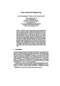
1 Introduction Effective programming needs supporting tools, like debuggers and profilers. In fact, for sequential programming languages, debugging can be done by step-wisely following the execution of a program. This also applies to Prolog and its procedural semantics expressed by SLD-trees. In general, such an approach is inapplicable to answer set programming due to its extremely declarative approach. Rather one has to commit to a particular computational model for making the computation of answers sets transparent. To this end, we advocate the graph-oriented computational model of the noMoRe system [2, 1]. This model is based on a rule dependency graph (RDG), whose nodes are given by the ground rules of the program and whose edges reflect positive and negative dependencies among rules. There is a positive edge from rule r to r 0 , if head (r) ∈ body + (r0 ); accordingly there is a negative edge from rule r to r 0 , if head (r) ∈ body − (r0 ). The computation of answer sets is then accomplished by gradually coloring the nodes of the graph by two colors (eg., green and red), reflecting the applicability status of the respective rule. Green nodes indicate applied rules, while red ones stand for inapplicable ones, relative to a possibly partial, putative answer set. Answer sets are represented in terms of their generating rules. For profiling answer set programming, we put forward a graphical approach by dynamically visualizing the coloration of RDGs. For this purpose, we extended noMoRe by a visualization module. This module has an interface (API) to the graph visualization system daVinci [3]. This part of noMoRe’s architecture is given in Figure 1. So noMoRe is no black box anymore but rather a vitreous one. Furthermore, the animated coloring sequences may be used for debugging ground logic programs under answer set semantics, because the user gets access to the full construction process of the answer sets. In particular, we are able to detect rules generating specific answer sets. For animation, one may chose among different levels of granularity. That is, the animation may be stopped and interactively resumed after coloring a single node, employing a particular operation, like a choice operation, for coloring or only when a coloring expressing an
Coloring Visualizer
daVinci
RDG
Fig. 1. Overview of the visualization of noMoRe.
answer set is obtained. (Stopping at particular rules is currently under implementation.) Other parameters influencing the visualization, like animation speed or node layout, are explained in Section 2 and summarized in Table 1. For illustration, let us consider a program consisting of the following rules: r1 r2 r3 r4 r5
: : : : :
b f f0 p w
←p ← b, not f 0 ← p, not f ← ←b
(1)
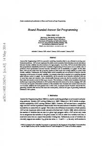
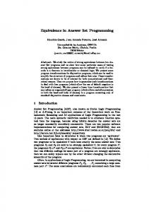
For later reference, assume this program is contained in a file named penguin.lp. The full sequence of coloring steps, leading to the two answer sets {p, b, w, f } and {p, b, w, f 0 } is given in Figure 2. This is the most fine-grained setting displaying each subsequent coloration step. Nodes of supposedly applied rules are colored in green; those standing for blocked ones in red. Whenever an answer set is obtained, as in the 6th and 10th instance, it is also printed by noMoRe. Nodes colored by choice operations are indicated by a double circle. The only such node is colored green in the 5th instance and red in the 9th one. Each choice leads to a different answer set. All other colorations are obtained through forward propagation. The animation capacities of daVinci also allow for visualizing and animating much larger graphs. Even graphs not fitting on a computer screen (in a certain resolution) can be animated, since daVinci automatically centers the considered node by horizontal and vertical scrolling. Although the detailed information obtained for very large examples is questionable, one can figure out which parts of a program are problematic due to extensive backtracking.
2 Using Visualization in noMoRe The flags show and animate influence the visualization component of the noMoRe system [1]. By setting flag show the visualization is activated, which enables noMoRe to use daVinci as output tool for RDGs and their colorings. After calling the command nomore/2 (or nomore/4) the daVinci API is used to draw the actual RDG. By setting the flag animate the daVinci API is used to animate the noMoRe coloring procedure during run time. Let’s demonstrate the visualization component by computing the answer sets of program (1):
4
4
5
3
3
4
daVinci V2.1
2
3
4
4
1
2
daVinci V2.1
5
3
5
3
1
2
daVinci V2.1
3
4
5
4
5
3
1
2
1
2
5
4
5
3
1
2
1
2
daVinci V2.1
daVinci V2.1
5
3
5
3
1
4
daVinci V2.1
2
4
1
2
1
daVinci V2.1
daVinci V2.1
2
daVinci V2.1
5
daVinci V2.1
2
1
daVinci V2.1
1
4
5
3
2
daVinci V2.1
1
4
5
3
Fig. 2. The visualization of the complete coloring sequence for program (1).
1. Start ECLiPSe, load noMoRe and ensure that set flag show is set by set flag(show). This activates the visualization tool. Furthermore, ensure that the flag animate is set by set flag(animate), since we are interested in an animated coloring sequence. Observe that due to flag dependency handling it is sufficient to set flag animate; then flag show is set automatically. 2. Continue by typing nomore(’penguin.lp’,0). After noMoRe has computed the RDG of Program (1) it is translated in the daVinci term representation. Then daVinci is started as a child process and the translated RDG is send to daVinci. See also Figure 2. 3. Now daVinci takes control and awaits an input by the user in order to process a number of coloring steps (a coloring step is the coloring of exactly one node.). The number of coloring steps which are performed without interruption depends on the setting of the Edit sub menu Stop At of daVinci. By default it is set to Every Node, which causes the noMoRe coloring procedure to stop after each single coloring step. However, via daVinci’s Edit menu we are able to change some daVinci specific settings, such as node presentation, dependency graph representation, stopping criterion for animated colorings and animation speed. For a complete description of the possible daVinci settings see Table 1. Finally, to continue the computation type Alt-G or click the Go-icon on the upper left side of the daVinci window.
4. Step by step every coloring of the noMoRe algorithm is visualized in daVinci (Figure 2). Observe that nodes which are used as choices during computation are marked by a double circle. 5. At last, a coloring corresponding to answer set {b, p, w, f 0 } is obtained. The noMoRe algorithm tries to compute alternative colorings via backtracking. This is modeled by uncoloring the corresponding nodes. See Figure 2 for the complete coloring sequence for program (1). Apart from the flags show and animate (see [1] for details on noMoRe flags) there are several settings affecting the visualization style. Those settings are accessible via the Edit menu of daVinci. See Table 1 for a complete listing of all possibilities to influence the presentation of RDGs and their animated colorings. By right clicking on a single node, it is also possible to change its representation. Edit menu items shortcut function Toggle Node Labels Alt-T toggles between internal noMoRe identifiers and the actual rules as node labels (same as flag names) Go Alt-G start animation until stopping criterion is reached Abort Alt-A abort answer set computation and exit daVinci Stop At no sub menu for choosing one of the following as stopping criterion for the animation: Choices, Each Node, Full Coloring, No Stop Animation Speed no sub menu for choosing the speed of animation, possible choices are: Slow, Normal, Fast Table 1. Possibilities to influence the representation of RDGs and their animated colorings via the Edit sub menu of daVinci.
noMoRe also represents different dependency graphs, so–called body-head (BH-) and rule-head (RH-) graphs. They can be used for visualization. Each body and head (rule and head) is represented through a single node in BH-graphs (RH-graphs). Finally observe that for every partial model the generating rules can be easily computed. Hence any ASP solver may use (partial) colored RDGs together with some graph drawing tool for visualizing its intermediate partial models as described in this paper.
References 1. C. Anger, K. Konczak, and T. Linke. NoMoRe: Non-monotonic reasoning with logic programs. In G. Ianni and S. Flesca, editors, Eighth European Workshop on Logics in Artificial Intelligence (JELIA’02), volume 2424 of Lecture Notes in Artificial Intelligence. Springer Verlag, 2002. 2. T. Linke. Graph theoretical characterization and computation of answer sets. In B. Nebel, editor, Proceedings of the International Joint Conference on Artificial Intelligence, pages 641– 645. Morgan Kaufmann Publishers, 2001. 3. M.Werner. davinci v2.1.x online documentation, 1998.