Floating-gate current multiplier and divider circuits are de- scribed. Measured .... VMOS is shown in figure 1, and the parasitic capacitances and conductances of ...
1
Programming Floating-Gate Circuits with UV-Activated Conductances YNGVAR BERG, TOR S. LANDE, Member, IEEE and ØIVIND NÆSS
Abstract— A programming technique for controlling the floating gates (FG) in ultra low-voltage (ULV) floating-gate circuits is presented. Simple ultra low-voltage floatinggate current scaling and level shifting circuits are discussed. The current scaling and level shifting are accomplished using only minimum sized transistors and floating capacitors. Floating-gate current multiplier and divider circuits are described. Measured results are provided. Keywords— Floating-gate, low-voltage, low-power, analog floating-gate circuits, current mode.
I. Introduction
A
S the current-mode approach to analog circuit design [1] is gaining interest due to better performance, another compelling reason for current-mode circuits is the decreasing power supply of digital microelectronics. The upside of sharing both silicon and power with digital electronics challenges the analog designer to come up with solutions for low-voltage circuits. As the power supply is reduced, the available headroom is shrinking, so current-mode design techniques provides some kind of relief by demanding much less headroom. One possible solution to the matching problem is postfabrication tuning using laser-trimming. Techniques requiring individual tuning of each powered-up circuit are slow and expensive. Another approach to threshold matching is to use MOS transistors with capacitive coupling to a floating gate. A change in the stored charge of the floating gate will effectively shift the threshold voltage seen from the capacitively coupled input terminal. The success of this approach is clearly dependent on both the accuracy and the overhead penalty in terms of silicon area and production cost. Different tuning schemes are used for controlling the charge stored on a floating gate. Several solutions involve injection-based techniques using high-voltage in combination with dedicated processes. Recent results [2] indicates that floating-gate tuning may be done in standard, double-poly CMOS. Utilizing the old technique of UV-light activated conductances, we are able to implement lowpower, area-efficient analog circuits. The threshold of FGtransistors may be tuned to suitable values [3]. In this paper we present a general method for tuning floating-gate transistors [3]. The effective threshold of the pMOS and nMOS transistors are adjusted to match a desired supply voltage and current level. The floating-gate UV-light programmable MOS transistor (FGUVMOS) can be used to implement low-power/low-voltage digital and Manuscript received...........................Y. Berg, T. S. Lande and Ø. Næss are with the Department of Informatics, University of Oslo, Norway.
analog circuits [4], [5], [6]. The programming technique has been applied to a number of analog ULV current mode floating-gate circuits and ULV transconductance amplifiers [7]. In the following, we will apply the FGUVMOS transistors to design current-mode circuits for ULV operation, but in order to understand the design we have to explain some more details about FGUVMOS circuits in general. There is always one pMOS stacked on top of one nMOS transistor. The height is always two with a common drain-node, however additional MOS transistors may be added in parallel (both pfets and nfets). Each floating gate may have several inputs connected through floating capacitors, compensating for the limited stacking. All FGUVMOS circuits must be tuned or programmed using short-wave UV-light (UV-C) [3], [8]. Note that all transistors on a chip, or even a wafer, can be programmed simultaneously without using any additional programming circuitry. The ULV floating-gate analog circuits presented in this paper can operate down to approximately 100mV in weak inversion. In the following analysis all transistors are assumed to be in saturation, hence only the saturation voltage and required frequency response limit the minimum usable supply voltage. Typical supply voltages for the ULV floating-gate circuits are in the range 0.2V to 1.0V . In section II the FGUVMOS transistor and the generic FGUVMOS circuit is presented and the floating-gate programming technique is described in section III. The ULV floating-gate current mirror, inverter, scaler and level shifter are presented in section IV. In section V ULV floating-gate current multiplier and divider circuits are discussed [9]. II. FGUVMOS circuits To ensure a direct control of the effective threshold voltage or current level in the programming mode no series transistors are allowed between supply rails and outputs. Although the design space for a creative circuit designer seems rather limited with FGUVMOS circuits, it is possible to create a versatile set of circuit-elements with familiar behavior. The central design technique is the well-known capacitive division with the floating-gate as the divided node. Unlike traditional circuits, there is no leakage from the divided node under normal operation. For a multiple input FGUVMOS transistor each input has by design an effective coupling capacitance, Ci , to the floating-gate. The input signal (control gate) is attenuated with a factor ki = Ci /CT , where CT is the total load capacitance seen from the floating gate. ki is called the capacitive division factor for input i.
2
It is convenient to express the behavior of a FGUVMOS circuit as a modulation of the equilibrium condition. At the equilibrium point, the control inputs are equal to Vdd /2 and the transistor currents are equal to Ibec . For simplicity, we will model the weak inversion behavior knowing that a similar analysis may be done for strong inversion as well. The input modulation of the drain current as a function of 1 the ith input terminal may be expressed as exp{ nU (Vi − t Vdd /2)ki }. The accumulated drain current modulation of Q 1 m inputs is expressed as the product m exp{ (V − i i=1 nUt Vdd /2)ki }. The effective drain current of a multiple input n-type FGUVMOS transistor may then be written as
Ids(nMOS) = Ibec
m Y
exp{
i=1
UV window Pad window Poly2 Poly2/ Poly1
Metal (gnd)
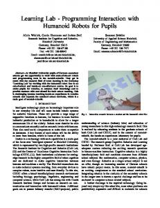
Fig. 1. Layout of the n-channel FGUVMOS transistor.
C2
1 (Vi − Vdd /2)ki }, nUt
Gf2
C gb
Cgd
Ggd
Gf1
where Ibec is the programmed equilibrium point current, that is the drain-source current of any FGUVMOS transistor with all control inputs equal to Vdd /2. The drain current of a multiple input p-type FGUVMOS transistor may then be written as
poly2
m Y i=1
exp{
= Ibec
m Y i=1
Imin
Cgs G gs
diffusion
1 ∗ (Vdd /2 − Vi )ki } ≡ Ids(nF ET ) , nUt
assuming that the slope factor of the p-type- and n-type transistors are equal. Furthermore, we may express the min and max currents of the n-type transistor in terms of the balanced equilibrium current and current modulation Imax
Ggb
poly1 substrate
Ids(pMOS) = Ibec
C1
exp{
1 Vdd ki } 2nUt
Pm = Ibec R i=1 ki Pm = Ibec R i=1 −ki (Ibec )2 ∗ = ≡ Imax , Imax
(1) 1 where R = exp{ 2nU Vdd }. Assuming that t the current range (or noise margin) is R2 .
Pm i=1
ki = 1,
III. Tuning floating-gate circuits with UV-light A. The basic programming technique The traditional way to control or charge/discharge a floating-gate is to employ electron tunneling and/or electron injection. In order to use the floating-gate transistors efficiently we need to be able manipulate the floating-gate charge without adding significant programming/tuning circuitry. In order to initiate FGUVMOS circuits, we need to access all floating-gates simultaneously through a resistive coupling. When exposing the gate-source/gate-drain regions to UV-light (250nm) a UV-activated conductance [8]
Fig. 2. Two input FGUVMOS transistor, where C1 and C2 are the floating capacitors and Ggs is the programming UV-activated conductance. Cgd , Cgs and Cgb are parasitic capacitances and Ggd , Ggb , Gf 1 and Gf 2 are parasitic UV-activated conductances.
is temporarily connecting the source/drain to the floatinggate. By using metal layers and/or passivation as a shield we may activate any desired UV-conductance between source/drain, or even control gate, terminals and the respective floating-gates. The layout of a two-input FGUVMOS is shown in figure 1, and the parasitic capacitances and conductances of a two-input FGUVMOS transistor are shown in figure 2. The entire chip is exposed to a single UVsource and the UV-activated conductances will disappear once the UV-light is removed. All floating-gate transistors will be tuned simultaneously. The programming technique may be used to reprogram the chip to different supply voltages and current levels (effective threshold voltages). A simplified FGUVMOS tuning technique was presented in [10], [11]. The FGUVMOS inverter is shown in figure 3. In the operative mode (normal biasing) there are no resistive connections to the floating-gate. In the programming mode (reverse biasing) the desired UV-activated conductances Gngd and Gpgd are present. The parasitic UVactivated conductances Gngs , Gnf , Gngb , Gpgs , Gpf and Gpgb , shown in figure 3 b) are determined by the layout and must be considered when designing the FGUVMOS circuits. The overlap capacitance Cgd is added to the Early effect and can be observed as an increased output conductance. By increasing the floating capacitors compared to the inherent MOS capacitors and increasing the transistor
3
V− G pf
Cp
G pgd
V fgp V well V fgp
V in
G pgs
Vdd /2
V out Cn
Cl
G ngs
V fgn
G pgb
V out
G ngb
Cl
V fgn V psub Cn
G ngd
B. FGUVMOS parasitics and second order effects
G nf
V+
a)
b)
Fig. 3. Single input FGUVMOS circuit. a) Operative mode (normal biasing) and b) programming mode (reverse biasing). 0.4
Vout (V) UV−light
0.35
0.3
0.25
0.2
0.15 0
5
10
15 time (minutes)
20
25
The FGUVMOS transistor conductances and capacitances are shown in figure 2. The UV-activated programming conductance Ggs appears as a resistive connection between the floating-gate and diffusion wherever a UVwindow (stippled line) allows UV-light to penetrate to the transistor. C1 and C2 are the floating input capacitances between the control gates and the floating-gate. The value of the active conductances and capacitances compared to the parasitics are of course dependent on the actual layout. Benson and Kerns [8] model the nonlinear UV-activated conductance. Due to the small UV-activated current the time constants are very large (minutes for minimum transistors for the 0.8µ double poly AMS CMOS process [12]). The time constant, however, are proportional to the floating-gate capacitance. For small devices in modern CMOS processes the time constant can be reduced to seconds.
30
Fig. 4. Measured FGUVMOS inverter output while exposed to UVlight and reverse biased for 0.8µ double poly AMS CMOS process. The supply voltage is 0.5V. A 4W disassembled UV-eraser was used for tuning.
length the drain conductance can be reduced to an acceptable level for digital circuits and amplifiers. When reverse biasing the inverter, see figure 3 (b), that is applying a more positive voltage on Vss compared to Vdd , the source and drain terminals are interchanged leaving us with a low impedance common source output. The FGUVMOS programming technique can be described in a number of steps: 1. Decide the operative (normal biasing) supply voltage Vdd . The optimal supply voltage may vary among applications. 2. Apply Vdd /2 to all external inputs. The digital gates and analog sub-circuits are programmed to get Vdd /2 at any output or internal node when all inputs are Vdd /2. 3. Apply the programming voltages at the supply rails, V− at Vdd and V+ at Vss . The supply rails are used to provide the programming voltages and the circuits are reverse biased. The effective threshold voltage seen from the control gate is determined by the programming voltages. The threshold voltage of the gates can be programmed to allow “perfect” DC transfer characteristics. 4. Terminate the programming by removing the UV-light source when any output converges to Vdd /2. Figure 4 shows the FGUVMOS inverter output in
4 3.5 3 Vwell and Vss (UV−light), Vwell
Cp
the programming mode for 4 identical inverters on 4 different chips. The initial floating-gate voltages may vary. If the the outputs converges to an undesired value (6= Vdd /2) either V− or V+ has to be altered. Normally we use only one set of programming voltages for a chip. 5. Set the biasing voltages to normal values. All floating-gate have been programmed simultaneously without accessing the transistors, gates or sub-circuits individually.
2.5
Vdd=0.7V Vdd=0.5V Vdd=0.3V
2 Vdd=0.7V 1.5 Vdd=0.5V 1
Vdd=0.3V Vdd=0.7V
0.5 Vdd=0.5V 0 Vdd=0.3V −0.5 −9 10
−8
−7
10
10
−6
10
Ibec (A)
Fig. 5. Programming voltages; ’- -’ lines represents V+ and solid lines represents Vwell as a function of Ibec . The programming voltage V− for the p-type FGUVMOS transistor is equal to Vdd /2 − 0.1V . The operative Vwell (’-.’ lines) is used to weaken the pFET.
The programming voltages applied to the FGUVMOS inverter are shown in figure 5. Notice the high positive programming voltage required to program the equilibrium current or effective threshold voltage. There are two factors that contribute to the rather large programming voltage; first, the inherent work function [13] of the transistors and secondly, the parasitic UV-activated conductances. From figure 5 we can estimate the value of the programming conductance compared to the lumped parasitic conductance to
4
−6
10
−7
10
−8
10
Ids (V)
approximately 30%. The parasitics can be reduced by narrowing the UV-window or using “round transistors” [14]. The large work function difference is rather destructive and limits the programmability of the p-type transistor (n-type poly1). When applying V− = 0V on the p-type transistor (Vdd ) the floating-gate of the pFET will end up at approximately −1V , hence the pFET operates in strong inversion and is normally to strong compared to the nFET. However, we may use the back-gate of the pFET to adjust the pFET current. Modern processes offer p-type as well as n-type poly1, which can be utilized to improve the symmetry of the pFET and nFET in the programming mode, and to improve the programmability of the pFET in particular.
−9
10
−10
10
−11
10
−12
10
0
0.1
0.2
0.3
0.4
0.5
0.6
0.7
prgramming current - Vss (A)
Vin (V)
10
-6
10
-7
10 -8
Fig. 7. Measured FGUVMOS inverter currents (nFET) for different supply voltages,’- -’ represents Vdd = 0.3V , solid line represents Vdd = 0.5V and ’-.’ represents Vdd = 0.7V . The current level (equilibrium current) vary from 2nA to 200nA. Iphoton=nA
Cdg=Csg=0
0.7 Ibec=200nA
10 -9
Ibec=4nA
0.6 Ibec=2nA
0.5
10 -10
Ibec=180nA 0.4 Vout (V)
10 -11 Cdg=Csg=0 Iphoton=1pA 10 -12 -9 10
10
-8
10
-7
10
-6
Ibec=4nA
0.3
0.2
Ibec=200nA
Ibec (A) 0.1
Fig. 6. The nFET programming current as a function of the equilibrium current. The circles represent measured values, while the solid line is based on a model. The supply voltage is 0.7V . The stipled lines represent simplified models.
In order to examine the parasitic capacitances, the nFET current of the FGUVMOS inverter is measured in the programming mode and in the normal mode after flipping the supply rails. When flipping the supply rails from reverse biased programming mode to normal mode the floating-gate voltages should be retained. However, when reversing the supply rails the source/drain terminals are interchanged and we should expect a small change in the floating-gate voltage due to the non-zero parasitic capacitance Csg and to some extent Cdg . The nFET current of the FGUVMOS inverter is measured in the programming mode and shown in figure 6 as a function of the equilibrium current. A model of the FGUVMOS inverter implemented in matlab [15] using the EKV model [16] including parasitic capacitances and a photon induced current Iphoton (nA )is shown in the figure (solid line). The parasitic capacitances Csg and Cdg will effectively contribute to a reduced equilibrium current for current levels above a few nano amps. The photon induced programming current is due to a parasitic photo diode located in the UV-window. The photon current is dependent on the light intensity and wave length and can be reduced. We can see that the model including the photon induced current and the parasitic capacitances clearly fits the measured data. The FGUVMOS inverter, or any FGUVMOS circuit,
0 Vdd=0.3V −0.1 0
0.1
0.2
Vdd=0.5V 0.3
0.4
Vdd=0.7V 0.5
0.6
0.7
Vin (V)
Fig. 8. Measured FGUVMOS inverter characteristics for different supply voltages and current levels.
may be programmed to different current levels and supply voltages as shown in figure 7 and 8. The inverter threshold can be set to Vdd /2 for all supply voltages and current levels. IV. The floating gate current mirror, inverter, scaler and level shifter The split floating-gate mirror circuit [17], [5] is shown in figure 9 (a). The floating gates of the current mirror are controlled through capacitor Cni and Cno . As for all FGUVMOS circuits we have that when the input Vin is equal to Vdd /2 the output Vout is equal to Vdd /2, and the floating gate voltages are equal. If we choose Cno /Cni > 1, the error due to finite drain conductance can be reduced. We may explore the symmetry and make a current mirror with an inverted output as shown in in figure 9 (b). In this way we get a true analog current inverter. The input current of the single input FGUVMOS circuits in figure 9 (a) may be expressed as Iin = 1 Ibec exp{ (nU (Vin − Vdd /2)kni } T The output current of the current mirror may be ex-
5
Po
I out
Po
Po
I in
C po
I in
C po
I in
I in
Vout
V in
V out
V in
C3
V in
V out I out
out V out I
V in
C2 C ni C no
C ni
C no
I out Ni
No
Ni
C3
Ni
C2 No
Ni
No
C1
(b) Current inverter
(a) Current mirror
C1
Vb
Vb
(a) Fig. 9. FGUVMOS circuits; (a) current mirror and (b) current inverter.
(b)
Fig. 11. Floating-gate current expansion and level shifting circuit.
−7
10
As expected the output conductance compensation is effective. The dynamic range of currents are close to three orders of magnitude for a supply voltage equal to 0.7V and a capacitive division factor (kno /kni ) equal to 1.07. The split gate in-out characteristics are linear and the error is significantly reduced compared to the common gate design. Note that the split-gate current mirror do not have the built-in feedback mechanism through the Cgd capacitor which is present in normal MOS- and common-gate floating current mirrors. A specific capactive division factor can be used for a wide range of equilibrium current levels [6], [5]. Consider the current mirror and current inverter in figure 9, the output voltage Vout is a function of the input current ∗ or input voltage Vin , Vout = Vdd − Vin ≡ Vin
current inverter
−8
10
Iout
current mirror common gate
current inverter common gate −9
10
current mirror −10
10
−10
−9
10
−8
10
10
−7
10
In
Fig. 10. FGUVMOS circuit characteristics; current mirror and current inverter.
pressed as Iout
= Ibec exp{
1 (Vin − Vdd /2)kno }. (nUT
(2)
If kno = kni , Eq. 2 reduces to Iout
= Ibec exp{
1 (Vin − Vdd /2)kni } = Iin . (nUT
Iout (3)
Along the same lines we may find the transfer function of the current-inverter for kpo = kni : Iout
The current expansion circuit is shown in figure 11. Note that the circuit may be used to compress rather than expand if s = k3 /k2 < 1. The currents can generally be inverted by using an analog current inverter shown in figure 11 (b) [11]. The output current of the mirror circuit shown in figure 11 (a), assuming that s = k3 /k2 > 1, may be expressed as
1 (Vdd /2 − Vin )kpo } (nUT 1 ∗ = Ibec exp{ (Vdd /2 − Vin )kni } = Iin . (nUT = Ibec exp{
1 (Vin − Vdd /2)k3 } nUt 1 = Ibec (exp{ (Vin − Vdd /2)s}) nUt 1 = (Ibec )1−s exp{ (Vdd /2 − Vb )k1 s}(Iin )s nUt 1 (Iin )s = exp{ (Vdd /2 − Vb )k1 s} , (5) nUt (Ibe )s−1 = Ibec exp{
1 (Vdd /2−Vb )k1 s} resembles where k1 +k2 ≤ 1 and exp{ nU t s
(4) The accuracy of the current mirror and current inverter may be increased by optimizing the ratio Cno /Cni and Cpo /Cni [6] to compensate for the drain conductance. The current mirror and current inverter characteristics are shown in figure 10 together with a common-gate approach.
) the level shifting and (I(Ibein)s−1 is the current scaling term. If Vb = Vdd /2 the level shifting term becomes equal to 1. If the supply voltage is equal to 0.7V the expansion is close to 10000 for s = 3. A current expansion of 10000 may thus be implemented using minimum sized transistors and two small floating capacitors where the large ratio is achieved by reducing the total area, that is we reduce the
6
Vb
V b2
C1
C4
I in
Po
V in
I in
V out I out C2 Ni
C3
V in
C3 No
C1
Po
I in
I in
out V out I
V in
V out C2
C2
I out
C3
Ni
Ni
C3
V in C2
No
Ni
C1
C4
C1
out V out I
Vb
(a)
(b)
V b1
V b2
V b1
(a)
Fig. 12. Floating-gate current compression and level shifting.
(b)
Fig. 13. Floating-gate current level shifter.
capacitor C2 compared to C3 . The value of C2 is typically comparable to the transistor gate-oxide capacitance, thus the area consumed by capacitor C2 is comparable to a minimum sized transistor. The maximum dynamic level shift for a supply voltage equal to 0.7V is larger than 1000, and the current may be shifted both upwards and downwards. The value of k1 depends on k2 , that is, we have that k1 + k2 ≤ 1. If k2 is reduced to increase the gain the value of k1 may be increased, thus increasing the level shifting range. The output current of the current inverter shown in figure 11 (b) may be expressed as Iout
= exp{
1 (Ibe )s+1 (Vb − Vdd /2)k1 s} . nUt (Iin )s
= exp{
(6)
1 (Iin )s (Vb − Vdd /2)k1 } . nUt (Ibec )s−1
The values of k1 may depend on k3 , that is, we have that k1 + k3 ≤ 1. If k3 is reduced to increase the expansion, the value of k1 may be increased, thus increasing the level shifting range. The output current of the current inverter shown in figure 12 (b) may be expressed as Iout
= exp{
1 (Ibec )s+1 (Vdd /2 − Vb )k1 } . nUt (Iin )s
The circuits in figure 13 is presented to complete the possible configurations of the basic ”current mirror” circuit. The output current of the mirror circuit shown in figure 13 (a) may be expressed as Iout
1 (Vdd /2 − Vb1 )lk3 } nUt 1 (Iin )s · exp{ (Vb1 − Vdd /2)lk3 } , nUt (Ibec )s−1
= exp{
V b2 C7 V in
C1 I in
I out C5
V1
C6
V2 C2
V out C8
C3 I2 C4 V b1
Compress and level shift
The output current of the compression and level shifter circuit shown in figure 12 (a), assuming that s = k3 /k2 < 1, may be expressed as Iout
Expand and level shift
(7)
(8)
Fig. 14. Compress, shift, expand and shift circuit.
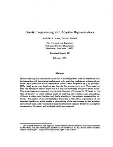
where s = k3 /k2 , l = k1 /k2 = k4 /k3 . We may use the circuit as a pure level shifter if s = k3 /k2 = 1, A test circuit (figure 14) was fabricated in AMS 0.8µ process using minimum sized transistors and coupling capacitors up to twice the size of the gate area. Figure 15 exhibit the tuning process. The currents in the two current branches in figure 14 was measured every minute during the tuning process. The currents are starting out way off in the lower left corner. The output current is increasing fast to a high value slowly recovering to its desired value. The compressed and shifted internal current is monotonically increasing to its desired value. The resulting currents after 30 minutes of programming are shown in the inset where the dashed line is the output current after a compression and expansion and the solid line uncover the internal compressed current. In this measurement no ∗ shifting was applied by setting Vb1 = Vb2 . In order to show the quality of our tunable current mirror the circuit in figure 14 was used in two ways, 1) compress/shift up — expand/shift down and 2) compress/shift down — expand/shift up. By applying different biasing to the Vb1 and Vb2 inputs both functions could be shown. The solid line shows expand/shift upto fairly high currents approaching strong inversion. The linearity of the following
7
-6
10
-7
10
Po
-8
10
I in2
I in1
C o3
C o4
-9
Iout (A)
10
-10
10
V in2
V in1
-7
10
I Po V po
V no I No
-11
10
-8
C i1
10
-12
10
C i2
C o1
C o2
Ni2
Ni1
No
-9
10
-13
10
-10
10
-10
-9
10
-8
10
-13
10
-12
-11
10
10
-10
-9
10
10
-7
10 Iin (A)
-14
10
-6
10
-8
10
-7
10
10
-6
10
Fig. 17. FGUVMOS current multiplier.
Iin (A) −7
10
Fig. 15. Measured result of the tuning process. The output currents are measured during the chip tuning. The currents are measured every minute. The resulting currents after 30 minutes adaptation are shown in the inset.
Ipo, Iin2=Imin
Ipo, Iin2=Ibec −6
−8
10
10
Ino, Iin2=Imax
Iout
−7
10
Ipo, Iin2=Imax
−9
10
Ino, Iin2=Ibec
−8
I2, Iout (A)
10
−9
10
Ino, Iin2=Imin
−10
10
−10
−9
10
−8
10
10
−7
10
Iin1 −10
10
Fig. 18. FGUVMOS current multiplier characteristics. −11
10
−10
−9
10
10
−8
10 Iin (A)
−7
10
−6
10
1/2 in equation 9 we get IN o
Fig. 16. The measured results showing both compression, expansion and shifting are shown with two measurements.
IP o compressed/shifted current is still very good (lower solid line). The dashed lines show compress/shift to picoamps followed by expand/shift back to the applied input current level maintaining good linearity. V. Current multiplier/divider circuits A current multiplier, shown in figure 17, with extended dynamic range and better symmetry, compared to implementations reported earlier in [17], may be implemented as a FGUVMOS circuit. Applying our equilibrium analysis we find the output current, IN o , may be expressed as IN o
= Ibec (
Iin1 kko1 Iin2 kko2 ) i1 ( ) i2 . Ibec Ibec
(9)
Again if ko1 /ki1 = ko2 /ki2 we have that IN o = Ibec {(Iin2 Iin1 )/(Ibec )2 }ko1 /ki1 . In figure 18 the simulated output of the current multiplier is shown. An interesting feature is revealed when playing with the terms ko1 /ki1 and ko2 /ki2 . If we let ko1 /ki1 = ko2 /ki2 =
p Iin1 Iin2 I2 = √ bec . Iin1 Iin2 =
As illustrated, different compressive or expansive functions might be added just by changing capacitive ratios. To make the picture complete, we present the FGUVMOS current divider. The output current IN o in figure 19 may be expressed as IN o
= Ibec (
Iin1 kko1 Ibec kko2 ) i1 ( ) i2 . Ibec Iin2
If ko1 /ki1 = ko2 /ki2 we have that IN o = Ibec (Iin1 /Iin2 )ko1 /ki1 . The simulated output currents of the improved current divider are shown in figure 20. A slightly simplified version of the circuit in figure 18 was implemented in AMS 0.8µ CMOS using minimum sized transistors. One of the input-current branches was removed and replaced with a direct capacitive coupling to a nMOS output transistor. Before testing, the circuits were programmed using a standard 4W UV-eraser according to the procedure required for FGUVMOS transistors.
8
Pi
The measured performance of a current multiplier is shown in figure 21 with a supply voltage of 0.7V . The output current is measured as a function of the input current while varying the multiplying input voltage. Note that a pure current-mode version of this circuit would not achieve a dynamic range of this magnitude, but with one voltagemode input terminal, we could exceed the 0.7V power supply voltage. For higher current-levels transition to strong inversion may be observed, but for weak inversion the linearity is exceptional.
Po
I n1
C o4
C i2
I Po
C o3
V po
V in2 V in1
V no I No C i1 C o2
I in2
C o1
Ni
No
VI. Conclusion A programming technique for floating-gate circuits has been presented. The floating-gates are programmed using the supply rails and UV-light, hence no additional programming circuitry is needed. The tuning technique is used to program a FGUVMOS inverter to different current levels and supply voltages. The programming technique can be used for ULV analog floating-gate circuits as well. The ULV floating-gate current mirror, curent scaler, current level shifter, current muliplier and current divider have been presented.
Fig. 19. FGUVMOS current divider.
−7
10
Ipo, Iin2=Imax
Ipo, Iin2=Ibec −8
10
References Iout
Ino, Iin2=Imin
[1]
Ipo, Iin2=Imin
[2] −9
10
Ino, Iin2=Ibec
[3] Ino, Iin2=Imax
−10
10
−10
−9
10
−8
10
−7
10
10
[4]
Iin1
Fig. 20. Hspice simulation of the FGUVMOS current divider output.
[5] [6]
−5
10
[7] −6
10
[8]
−7
10
−8
[9]
Iout (A)
10
[10]
−9
10
−10
10
[11]
−11
[12]
10
[13]
−12
10
[14]
−13
10
−10
10
−9
10
−8
10 Iin (A)
−7
10
−6
10
Fig. 21. Measured performance of the current multiplier. The output current as a function of the input current was measured for different multiplication factors (voltages).
[15] [16]
“Analogue IC Design: The Current-mode Approach”, Edited book by Toumazou C. et. al., Peter Penegrinus, 1990. C. Diorio, P. Hasler, B. A. Minch, and C. Mead, “A Complementary Pair of Four-Terminal Silicon Synapses,” Analog Integrated Circuits and Signal Processing, vol. 13, nos. 1-2, pp. 153-166, 1997. Y. Berg and T. S.Lande: “Area Efficient Circuit Tuning with Floating-Gate Techniques”, In Proc. IEEE ISCAS, Orlando, USA, May-June 1999. Y. Berg, D. T. Wisland and T. S. Lande: “Ultra LowVoltage/Low-Power Digital Floating-Gate Circuits”, IEEE Transactions on Circuits and Systems, vol. 46, No. 7, pp. 930– 936,july 1999. Y. Berg and T. S. Lande: “Tunable Current Mirrors for Ultra Low Voltage”, In Proc. IEEE ISCAS, Orlando, USA,, May-June 1999. Y. Berg and T. S. Lande: “Ultra Low-Voltage Current Mirrors and Pseudo Differential Pairs”, In Proc. IEEE ASIC, Rochester, USA, pp. 109–114, Sept. 1998. Y. Berg, T. S. Lande, Ø. Næss, and H. Gundersen “Floating Gates; ultra low-voltage amplifiers,” Submitted to IEEE Transactions on Circuits and Systems, special issue on floating gates. R. G. Benson and D. A. Kerns: “UV-Activated Conductances Allow For Multiple Scale Learning”, IEEE Transactions on Neural Networks, vol. 4, no. 3, pp. 434–440, May 1993. Y. Berg and T. S. Lande: “Ultra Low Voltage Current Multiplier/Divider”, In Proc. IEEE ICECS, Cyprus, September 1999. Y. Berg and T. S. Lande: “Programmable Floating-Gate Mos Logic for Low-Power Operation”, In Proc. IEEE ISCAS, pp. 1792–1795, Hong Kong, June 1997. Y. Berg, D. T. Wisland and T. S. Lande. “Floating-Gate UVMOS Inverter”, In proc. IEEE NORCHIP, november. 1997. Austria Mikro Systeme International: “0.8 um CMOS Process Parameters”, no. 9933006, rev. B, Mar. 1997. Niemen Ed.: “Semiconductor Physics and Devices”, 2nd Edition, IRWIN ISBN 0-256-20869-7. N. H. E. Weste and K. Eshraghian: “Principles of CMOS VLSI design, A System Perspective”, Second edition, Addison-Wesley Publishing Company, pp. 333, 1993. Matlab reference Guide: “The Math Works Inc.”, Natick, MA. C.C. Enz, F. Krummenacher and E.A. Vittoz: “An analytical MOS Transistor Model Valid in All Regions of Operation and Dedicated to Low-Voltage and Low-Current Applications.”, Special issue of the Analog Integrated Circuits and Signal Processing journal on Low-Voltage Design, vol. 9, pp. 27–44, July 1995.
9
[17] B. A. Minch, C. Diorio, P. Hasler and C. A. Mead: “Translinear Circuits Using Subthreshold Floating-Gate MOS Transistors”, Analog Integrated Circuits and Signal Processing, 9, No. 2, pp. 167–179, 1996.
Yngvar Berg received the M.S. and Ph.D. degrees in Microelectronics from the Dept. of Informatics, University of Oslo in 1987 and 1992 respectively. He is currently working as a professor with the same department. His research activity is mainly focused on low-voltage/lowpower digital and analog floating-gate VLSI design.
Tor S. Lande (M’93) is currently serving as a professor at Dept. of Informatics, Univ. Of Oslo. His primary research is related to microelectronics. His interest in Neuromorphic Engineering or Analog Computational Systems has lead to focus on low-power circuit design. The understanding of representation and computation in different computational paradigms have spawned novel ways of designing both large and smaller systems using state-variables like frequency modulation. Driven by the demands from practical application focus on technology, especially low-power techniques and floating-gate structures, has taken most of his interest lately. He is the author or co-author of more than 60 publications and is serving as a reviewer for several international journals. He is a technical committees member for several international conferences. He is a member of the IEEE.
Øivind Næss received the B.sc and M.Sc. from the Department of Informatics, University of Oslo, Norway in 1997 and 1999, respectively. The M.Sc. thesis concerned design of FGUVMOS analog filters. His main interests are low voltage analog CMOS design, esp. amplifiers and filters. He will pursue as a Ph.Dstudent with the Microelectornics Group, Department of Informatics, University of Oslo.