It is foreseen that the transfer structures (CTS) of the drive linac will produce 40 MW, 11.4 ... and and measured RF-wise with the beam simulating wire method.
Progress with the CLIC Transfer Structures(CTS). G. Carron & L.Thomdahl CERN, 1211 Geneva 23, Switzerland ABSTRACT 2.84 ns, is met by using a forward wave in the waveguide, as shown in Fig. 2 where a single bunchlet is It is foreseenthat the transferstructures(CTS) of the drive followed as it crossesthe structure, linac will produce 40 MW, 11.4 ns, 30 GHz rf power pulses superpositionin the waveguideof 43 There is constructive At present for accelerationpurposesin the CLIC main linac. successiveRF wave packages (from the 43 bunchlets) spaced a real size Cu 30 GHz CTS has been brazed, vacuumtested in time by one RF period (33.3 ps) to create a rising flank and and measured RF-wise with the beam simulating wire (1.4 ns), a flat top (1.4 ns) and a falling flank (1.4 ns) for the method. Furthermore a simplified version is ready for power output pulse. Four successive bunchlet trains (43 bunchlets testing with an MIT 33 GHz FEL power source. each) create a global pulse approximately 11.4 ns long (flat top) to fill a module of the CLIC main linac.
INTRODUCTION
In the CLIC design the drive linac uses four trains spaced by 2.84 ns of 43 bunchlets (1 cm bunchlet spacing, 40 nC each) to produce via the transfer structures 30 GHz power pulses of 40 MW for the main linac [I]. With the 2.84 ns train spacing all 4 trains can be preacceleratedat 352 MHz. The structure shown in Fig. 1 can be considered as the output stage of a relativistic klystron. It consists of a smooth round beam chamber containing two coupIing slits into two periodically loaded (with “teeth”) rectangular waveguides. The TEM wave accompanying the bunchlets has radial electrical fields and azimuthal magnetic ones at the slits causing constructive excitation of a hybrid forward mode in the waveguides (useful power) and non constructive excitation of the backward mode (not useful, terminated). The forward output is intended for acceleration in a module of the main linac. The condition for constructive interference between the beam and the hybrid mode is that the mode has a phase velocity equal to c at the operating frequency; this is obtained by loading the waveguide with the periodic “teeth” structure.
Fig. 1: Upper half of the vertically symmetric CTS showing the round beam chamber and the upper periodically loaded (“teeth”) waveguide with V3 cells.Units:millimeters. A particular CLIC requirement, that the structure should work as a “pulse stretcher” by extracting from each train of 43 bunchlets (lasting 1.4 ns) a 40 MW RF pulse lasting
d
b)
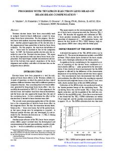
Fig. 2: Arrival of a bunchlet at the structure. The waveguide 4 extremity is immediately energised (no output power yet). The bunchlet exits the structure g/c later leaving the :aveguide energisedover the length g( 1-pgr), Total RF pulse duration: g(l/pgrl)/c pgr: normal&d group velocity in the waveguide. Related work is the development of power phase shifters and, inspired by the SLAC SLED-II studies, investigations into the use of longer RF pulses (than 11.4 ns) from the CTS (by a factor 3-4) combined with RF pulse compression. With longer RF pulses the drive beam bunchlet generation should become easier since the total drive beam charge of 7.04 PC would be distributed over more bunchlets.
FIRST 30GHZ
COPPER CTS PROTOTYPE
Recently a real-size prototype has been built to investigate manufacturing possibilities as well as precision and RF breakdown problems. The design should be suited for mass production: the 2 drive linacs of the project would require about 12 000 units distributed over 6 Km of active length. The construction used, see figs. 5 and 6, consists of 2 side pieces forming the central beam chamber and the coupling
2167
slits held together by 2 comb like precision spacers. The necessarytolerances (-Spm) were evaluntcd with MAFIA [3] and it turned out that mainly the teeth parametersmattered for the beam/wave synchronism; the most important being the distance between teeth. One simplified prototype for 33 GHz power testing at an MIT 40 MW FEL power source has been complctcd.
-
&
____
inserts. High precision alignment is achieved with 3mm stainless(unbrazed)pins(courtcsy KM, Osnabrueck).
-------__- --_-. .- . __-._______ -=z-z===zz
Fig. 3: Vertical cross sections through the Cu CTS prototype showing the central beam chamber and the periodic waveguides and a top view with flanges for WK28 waveguide.
Fig. 5: Wiew of 2 adjacent sections of CTS inside a long, say 3 metres, chain of structures. The design is thus based on the 2 long continous medium precision machined Cu profiles for sidepieces (shown in horiz. position) forming the beam chamber with its coupling slits. The high precision comb spacers and output inserts positioned by precision pins are equally visible(courtesy KM, Osnabrueck).
Fig. 4: One end of the 30 GHz CTS prototype made from 2 sidepieccs and 2 precision spacers forming the waveguide ceiling with periodic loading. Only 1 sidepiece positioned horizontally and one spacer are shown. Matched bends to divert the power to the WR 28 output ports are introduced as
Fig. 6: Photograph of the end of one completed 30 GHz CIS prototype with its output port for WR 28 waveguide(to the right) shown together with an unbrazed sidepiece(to the left). The sidepiece in the middle contains one precision spacer forming the waveguide ceiling with periodic loading of one waveguide. One matched bend, introduced as an insert, to divert the power to the WR 28 output port, is visible together with the precision alignment pins. Only the inserts and the sidesof the spacersare Ag-plated for for the brazing of CIS.
F
2168
PREVIOUS INVESTIGATXONS WITH SCALE MODEL MEASUREMENTS The TEM fields of the bunchlets have been simulated by a ZO=300 R transmission line situated at the centrc of the beam chamber. At each extremity of the oversize model (scale factoe3.5, 8.6 GHz instead of 30 GHz) conical matching transitions from 300 to 50R had been installed adjacent to damping sections against TEM, TE and TM modes of the chamber. Thcrc was adiabatic matching of the hybrid mode to the terminated TElO output waveguidc by gradual “teeth size” reduction at the extremities(see figs. 3,4 and 5). The longitudinal beam coupling impedance ZL(w) of the model was obtained from a calibrated (the coupling slits were closed for calibration) measurement of the transmission S2I(o) along the wire in the frequency range O-40 GHz (This included the three first harmonics of the scaled bunchlet frequency 8.6 GHz): ZL(W) = 2 20 (l-S2l(W))
One of the 30 GfIz structures is intended for studies with beam in the CLIC test facility. It has recently been brazed and vacuum tested. The fine adjustment of the beam/wave synchronism(at 30 GHt) had been obtained by electrccrosion of the waveguide tecth(in 2 steps) and RF measuremen&with the wire method before the braze. The bmze using an electrodeposited 1.5cull Ag layer causedonly an insignificant frcqucncy shift. A measuredcoupling curve between the beam simulating wire and one wavcguidc output port is given by fig. 7.
/ S2l(W)
Multiplying the beam current spectrum i(w) with ZL(W) and applying an inverse Fourier transform, WCobtained the beam wake. In a similar way i(w) S’2l(w) and inverse Fourier transformation yielded the output power pulse(S’2 1: transmission from wire input to structure waveguide output
Fig. 7: Measured transmission between Oeamsimulating wire ‘andone waveguide output port The peak response is well centred at 30 GHz. Center freq. 30 GHz, span 5 GHz, 5 dB/div. vertically.
CONCLUSIONS In principle a structure capable of delivering the required power pulses for the filling of the main linac accelerating sections has been found. It remains to be shown that it can stand the required high fields without breakdowns. In the case of beakdowns diamond machining of the critical surfaces should be attempted.
ACKNOwLEDGEbIENTS
Fig. 7: Scaled CTS wire model for 8.6 GHz. The periodic waveguide has been cut into 2 pieces; the piece to the left is upside down to visualise the coupling slit and the periodic loading. The wire is too thin to be seen.
The structure concept based on a forward wave inside a periodically loaded TEIO waveguide with a coupling slit to the beam chamber and using constructive interference was suggested by W. Schnell. A first version was enginccrcd by T. Garvey[3].
REFERENCES Ill
Both wake and output pulse obtained with the wire method are in good agreement with results from MAFTA calculations [2]. In particular the MAFIA and the wire method indicate that HOW cause insignificant loss factors compared with the fundamental mode. RF leakage through the. coupling slits may be the phenomenon that prevents HOM confinement in the waveguide,
[?] [3]
2169
G.Carron and L. Thomdahl, “Impedance and loss factor measurements on a CLIC transfer structure” , 1992 EPAC Berlin, 24-28 March 1992, in CERN-SL/92-15 PO. A. Millich, Clic Transfer Structure Simulations using MAFIA. EPAC, Berlin, 1992 Proceedings. T. Garvey et al., RF Measurements on a possible Transfer Structure. CERN-LEP-RF/8635.