Computing and Informatics, Vol. 30, 2011, 987–1010
PROPERTIES FOR COMPONENT MODEL: THE DEFINITION PERSPECTIVE Hazleen Aris College of Information Technology Universiti Tenaga Nasional Jalan IKRAM-UNITEN 43000 Kajang, Selangor, Malaysia e-mail:
[email protected]
Siti Salwah Salim Faculty of Computer Science and Information Technology University of Malaya Lembah Pantai 50603 Kuala Lumpur, Malaysia e-mail:
[email protected]
Communicated by Ulrich Eisenecker
Abstract. The presence of a large number of component models to date should be able to offer software developers a wide variety of component models – which they can easily choose from – for their software development projects. However, the opposite situation is currently observed, where the presence of many component models has caused difficulties in making the selection. Lack of properties or characteristics that can be used as a basis to perform objective comparison between the existing models is believed to have caused the difficulties. In this paper, a list of component model properties is derived by thoroughly examining the available component model definitions. Results from a comparative analysis performed on six component models using the properties show that the properties enable a more objective comparison between the existing component models to be performed. Keywords: Component model properties, derivation of properties, comparative analysis
988
H. Aris, S. S. Salim
1 INTRODUCTION Component-oriented software development (COSD) is an approach in software development where software applications are produced by composing (software) components. To enable such composition, components have to be developed according to the specifications introduced in a component model. The need for components to comply with a component model is clearly stated by Councill and Heinemann [1] when they define component as “a software element that conforms to a component model and can be independently deployed and composed without modification according to a composition standard”. Compliance with a component model is also one of the prerequisites that distinguish components from other forms of packaged software [2, 3]. Therefore, the success of COSD largely depends on a clear definition and precise specification of a component model. Due to the significant role played by the component model, considerable amount of research effort has been spent on its specification and construction, resulting in the birth of a large number of component models. To date, at least 32 component models are available [4], which range from domain specific to generic component models. The presence of a large number of component models is expected to offer software developers a wide range of component models from which they can easily choose any suitable ones to be used in their software development projects. Instead, the opposite scenario is observed where their presence has made it more difficult for the software developers to find suitable component models [5]. Amongst the reasons that have caused the difficulties is the fact that existing component models vary from one another in many aspects [6], making comparison of the component models extremely difficult if not impossible. When comparison is not possible, a selection cannot be made and software developers resort to either creating a new component model when they need one or using only the commonly used component models such as EJB and COM. Both options have their respective disadvantages. Creating new component models is reinventing the wheel and adds up to the already large number of component models. Using only the most commonly used ones eliminates the chances of other component models being used, even though they have been introduced after considering the drawbacks of the commonly used component models [7, 8]. To rectify the situation, there is a need to have a list of component model properties or characteristics that can serve as a basis for comparison of existing component models. The properties can be regarded as the lowest level architectural elements that each component model should have or specify. The list of component model properties allows comparison between component models to be made in a more objective and directed manner. In this article, we present the outcome of our research to derive a set of component model properties from the perspective of component model definition. This means that the derivation of the component model properties is based on the elements that, by definition, constitute a component model. It is later extended to also include the architectural information entailed by the definitions.
Properties for Component Models
989
The rest of this article is organised as follows. Section 2 outlines the approach taken in this research. Component model definitions are presented in Section 3, followed by component model standards in Section 4. Section 5 refines component model standards to derive component model properties. In Section 6, we demonstrate how the derived component model properties are used to compare a selection of component models. The results of the comparison are presented and discussed in Section 7. Section 8 summarises related research, comparing and contrasting it with ours, and finally, Section 9 concludes the article. 2 METHOD First and foremost, a firm understanding of component model definition is required. To achieve this, we searched through all related literatures to gather as many component model definitions as possible. Four definitions were included, which are presented in Section 3. Even though the definitions vary from one another, it is believed that commonalities exist amongst them because they share the same purpose; to produce components that can fulfil the expectations of COSD. This becomes our hypothesis and the basis for the derivation of the component model properties. Therefore, each definition is reviewed in detail and compared against the others to extract the descriptions that are common across the definitions. These common descriptions are regarded as the essential elements that constitute the component model definition. These essential elements are found to be the standards that a component model should specify, known as component model standards. The standards can be seen as the lower level representation of the elements, which refines the granularity of the elements. Next, we establish the relationships between the standards and the corresponding architectural elements of a component model that are responsible for the specifications of the standards. Each architectural element is then hierarchically decomposed into more finite elements by reviewing the relevant literatures that discussed about them. From the decomposition, a list of component model properties under each element is identified. Evaluation of the properties is performed by comparing a number of selected component models against the properties. 3 COMPONENT MODEL DEFINITION Since there is no consensus yet on the definition of a component model, we have decided to take into consideration a number of component model definitions that are available to date. A total of four definitions from four different sources were eventually found and are quoted below. Although implicit definitions of component model also exist using other terms such as services and objects, only definitions that explicitly mention the term “component model” are considered, because they are more focused towards COSD and more relevant to the context of the discussion.
990
H. Aris, S. S. Salim
Definition 1. A component model specifies the standards and conventions imposed on developers of components. Compliance with a component model is one of the properties that distinguish components from other forms of packaged software [2]. Definition 2. A component model defines specific interaction and composition standards. First, it defines how to construct an individual component. Second, it enforces global behaviour on how a set of components in a component-based system will communicate and interact with each other [1]. Definition 3. A component model is a combination of a) a component standard that governs how to construct individual components and b) a composition standard that governs how to organize a set of components into an application and how those components globally communicate and interact with each other [9]. Definition 4. A (software) component model is a definition of [10] • the semantics of components, that is, what components are meant to be, • the syntax of components, that is, how [the components] are defined, constructed and represented, and • the composition of components, that is, how they are composed or assembled. It is found that the above definitions are in agreement with one another on the fact that a component model defines standards. This is highlighted in each definition. These standards are of two types, as stated in Definitions 2, 3, and 4. The first type of standard governs the construction of individual components and the second type of standard governs the interaction between the constructed components and their environment. This finding supports our earlier hypothesis that commonalities indeed exist in these definitions, which provides strong foundation for the derivation of component model properties. 4 COMPONENT MODEL STANDARD Bachmann et al. [2] started work on component standards by introducing three standards (and conventions) that constitute a component model. These standards are component types, interaction schemes, and resource binding. A component type is defined in terms of the interfaces that it implements [2]. It is a collection of component interface types, which describes the interfaces that components of this type must or may have at runtime [11]. A component type captures the semantics of a component’s behaviour, the kind of functionality it implements, its performance characteristics, and its expectations of the style of interaction with other components [12]. Different component types can play different roles in a system and participate in different types of interaction schemes. A component interacts with other components and also with its framework. Therefore, at least two kinds of interaction
Properties for Component Models
991
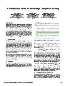
schemes exist; component-component interaction and component-framework interaction. The former deals with topological issues, such as the number of simultaneous connections allowed, while the latter concerns with resource management issues such as component lifecycle and thread management. Interaction schemes may be common across all component types or unique to particular component types. Resource binding binds a component to one or more resources. A resource is a service provided either by a framework or by some other components deployed in that framework. A component model should describe which resources are available to components as well as how and when components bind to these resources. From the description of each component model standard above, the following conclusions can be drawn regarding the component model standards and their relationships with the entities involved in COSD. 1. All of the three component model standards discussed above are defined by the component model developer, that is, the person who develops or constructs a component model. 2. Of the three component model standards, the first two standards, component type and interaction scheme, are the standards that need to be adhered to by the component developer, that is, the person who develops individual components in accordance with the chosen component model. 3. The third standard, resource binding, is the standard that needs to be adhered to by the component user, that is, the person who uses existing components from the repository to produce applications. In Figure 1, component types and interactions schemes are attached to the line connecting the component developer to the repository of pre-existing components and resource binding is attached to the line connecting the component users to the same repository to illustrate items 2 and 3 above. Figure 1 also emphasises the fact that component developers and component users do not necessarily have to belong to the same party. In fact, third party components usage is one of the desiderata of COSD [10]. 5 DERIVING THE PROPERTIES From the previous section, it is learned that first, component model definition is about specification of standards for components development and standards for components composition, and second, the standards for components development are component type and interaction scheme, and the standard for components composition is resource binding. The question now is: “Which part of a component model architecture is responsible for the specifications of its type, interaction scheme and resource binding?” The need to associate component model standards to the corresponding component model architecture elements that specify them is obvious. Without the association,
992
H. Aris, S. S. Salim
Component user
Component developer
uses Resource binding
produces
Interaction schemes
Pre-existing components deployed into
Applications
Component types
deposited into composed into Composite components
Fig. 1. Relationship between component model standards and entities in COSD
it is not possible to ascertain whether a particular standard is defined by a particular component model or not. To perform the association, four other research works that described the component model standards and means to achieve them are identified. These works however use differing terms to mean component model standards. The differing terms are summarised in Table 1. From the review of these works, the following associations between component model standards and corresponding architectural elements that are responsible for their specifications are determined: • component interface is responsible for the specification of component type, • contract is responsible for the specification of interaction schemes, and • composition mechanism should specify resource binding. In this article, the interface, contract, and composition are called the aspects of a component model. These aspects, however, are still too abstract to be used as a basis to determine whether a particular standard is specified by a particular component model or not. Each aspect therefore needs to be decomposed into a number of lower level architectural elements called properties that belong to each aspect. Sections 5.1 to 5.3 below elaborate the three component model aspects identified in order to derive their respective properties. 5.1 Interface An interface of a component is a specification of its access point [14]. Other resources access the services provided by the component through this point. As such, in an ideal component-oriented software development, the interface would be the only
993
Properties for Component Models Standard Component type
Councill [1] interface standard
Interaction schemes
interaction standard (superset of interface standard)
Resource binding
assembled connections (C-C), integrated connections (C-F)
Beugnard [13] basic or syntactic contracts behavioural contracts, synchronisation contracts, QoS contracts
Crnkovic [14] syntax or interface signature interface semantic (realised through contract)
*
*
Lau & Wang [15] semantic component inputs and outputs, system inputs and outputs design phase composition, deployment phase composition
* Information on deployment of components and applications is not found in the literatures. Table 1. Terms used to describe component model standards
means by which a resource accesses the provided services. From the definitions of interface found in [2, 14, 16], the following information regarding interface is extracted. • Component type is determined by the interfaces implemented. This is to ensure uniform composition [2]. • Interface is not only for components, but for all other elements that are involved in the composition process, such as connector and framework. In Acme [17], for example, a connector also has its interfaces. • Interface should express not only functional properties (also referred to as syntactic or signature part [14]), but also non-functional properties (also referred to as semantic or behaviour part [14]). The reason is, functional properties alone are not sufficient to express the quality attributes of a system composed from components [2]. • Interfaces specify the inputs and outputs of a component. • Non-functional properties, which are required to be specified in the interface include: – safety and progress – non-functional requirements, such as the specifications of behaviour, synchronisation, and quality of service (QoS), and – time and space requirements, which can be expressed using a contract [2, 14, 16].
994
H. Aris, S. S. Salim
Therefore, an interface consists of a signature part and a behaviour part, which is shown using a tree representation in Figure 2. Signature part specifies the inputs and outputs of a component. Behaviour part is specified in the form of contract. How these behavioural specifications are achieved using contract is explained in the next subsection.
signature part
specification of input(s) specification of output(s)
interface behaviour part (in the form of contract) Fig. 2. Constitution of the signature part of an interface
5.2 Contract As mentioned in Section 5.1, the behaviour part of a component can be specified more accurately using a contract. A contract states what the client component needs to do to use the interface of a component and what the provider component has to do to deliver the services promised by its interface [16]. Figure 3 shows an illustrative example of a contract between the provided and required interfaces of components C and D, taken from [2]. In the figure, PROD is the provided services that component D will implement iff component C implements the required services REQC . The same goes for the contract between PROC and REQD . This is called a reciprocal obligation [2].
Fig. 3. Contract between components [2]
What constitutes a contract then? The following are amongst the constraints that should be specified by a contract [2, 14, 16, 18]: invariant – the list of constraints that the component will maintain throughout its execution, precondition – the list of constraints that need to be met by the client, and postcondition – the list of constraints that the provided component promises to establish in return.
995
Properties for Component Models
With this information, Figure 2 is extended to include the constitution of a contract as shown in Figure 4.
signature part
specification of input(s) specification of output(s)
interface
precondition behaviour part invariant (in the form of contract) postcondition
Fig. 4. Constitution of the signature and behaviour parts of an interface
5.3 Composition Composition is a widely used term in COSD to describe the process of binding a component to one or more available resources to create an application [2, 19]. The available resources can be another component, a connector, or even the framework that governs the composition. Binding a component to resources involves questions of how and when composition occurs. These are termed the binding technique or binding mechanism and binding time respectively. 5.3.1 Binding Technique Binding technique is “the technique whereby parameters or connection points are determined and bound” [20]. At least two entities are composed (bound) in COSD; components and their framework [2]. Therefore, three possible types of composition exist; component-component composition, component-framework composition, and framework-framework composition as illustrated in Figure 5.
componentcomponent composition
componentframework
simple composition (C-C) component sub assembly (c-C) component deployment (C-F)
framework-framework Fig. 5. Types of composition
996
H. Aris, S. S. Salim
Component-component composition is the type of composition that enables interaction among components to deliver application functionality [2]. Component-component composition can be further divided into simple composition (C-C) between components and subassembly of a child (sub) component into its parent component (c-C)1 as shown in Figure 5. Component-framework composition is the type of composition that enables interactions between a component and its framework, hence enabling component deployment. These interactions enable frameworks to manage component resources. Framework in the context of our research is a “mainframe” that enables components to be plugged into it and is at the same time responsible for managing and monitoring their interactions [14]. An analogy given by [2] is to think of a component framework as a mini-operating system. In this analogy, components are to frameworks what processes are to operating systems. Therefore, the framework manages resources shared by components, and provides the underlying mechanisms that enable communication (interaction) among components. Other implementations of component framework are also possible, including framework implementation that is bundled with component implementation [2] and considering framework as component [21]. Nevertheless, the trend in component technologies seems to be towards framework as independent implementation [2], making the operating system analogy preferable. Framework-framework composition is the type of composition that enables interactions between frameworks. These interactions enable composition of components that are deployed in heterogeneous frameworks. Even though this is amongst the ultimate aims of COSD, research in this direction still has a very long way to go and most of the existing component models at present do not include specifications for inter-framework composition. Framework-framework composition is therefore beyond the coverage of our research and will not be included in deriving the properties of composable component models. Its exclusion is indicated by faded writing in Figure 5. 5.3.2 Binding Time Binding time is “the point in the lifecycle of a component when a parameter or connection point is determined and bound” [20]. One way of interpreting this definition is by thinking of binding time as a time line, with early binding at one end and late binding at the other, as shown in Figure 6. Binding of component to resources can take place at any point on the time line. At the two extremes, two types of binding are possible; late and early binding. Early binding requires that the component developer makes some decisions which effectively constrain how resource binding will occur later [2]. In Aßmann [20], this is referred to as static binding, where the decisions cannot be changed at runtime. Static binding occurs during component development or system assembly. 1
Note the use of lowercase c to distinguish from simple composition (C-C).
997
Properties for Component Models
Fig. 6. Early and late binding [2]
Late binding on the other hand means that the component developer makes no decisions that constrain future resource binding [2]. Also referred to as dynamic binding, this type of binding occurs at runtime. Each of the properties that constitute each of the aspects shown in Figures 2, 4, and 5 respectively are combined to form the properties for a component model from the definition perspective, shown in Figure 7. Composition includes componentcomponent composition and component-framework composition. However, if other elements such as connectors are also involved in the composition process, componentconnector composition can be added. This possible extension is represented as an ellipsis (. . . ) in the figure. For each type of C-C, c-C and C-F composition, interface that covers the signature part and behaviour part of the component or framework should be defined. Due to space constraints, interfaces for c-C and C-F composition are represented as " to indicate that they should be defined in the same way as the interface for C-C composition.
signature part
componentcomponent composition
componentframework
simple composition (C-C) component sub " assembly (c-C) component deployment (C-F) "
specification of input(s) specification of output(s) precondition
behaviour part invariant (in the form of contract) postcondition ...
framework-framework
... Fig. 7. Component model properties
Other ways of representing the properties are also possible, such as using feature modelling, which gives more details about each property, such as cardinality and relationships between properties. However, to compare existing component models, we would only want to determine the presence or absence of these properties, and for that purpose, tree representation is already sufficient.
998
H. Aris, S. S. Salim
6 COMPARING COMPONENT MODELS In this section, the component model properties derived in Section 5 are used to compare a number of selected component models as a way of evaluating the derived properties. The purpose of the evaluation is to determine the extent to which the derived properties can be used to perform an objective comparison between existing component models. To do this, a number of existing component models need to be selected as samples. Existing component models can be divided into two categories; industry-based component models and research-based component models. Industry-based component models, as the name suggests, are those that are being widely used in the industry [22]. Examples of industry-based component models include JavaBeans, COM+, and CORBA. Even though they are widely used in the industry, their adherence to the fundamental concepts of component model is still a subject of discussion. Amongst the reasons is that industry-based component models focus on practical problems and are described in technical terms, thus providing many implementation details that render their concepts and principles difficult to understand [22]. As opposed to the industry-based component models, research-based component models are the component models proposed by researchers by observing the core concepts of a component model in proposing them. In fact, a number of these research-based component models are also proposed after reviewing the pitfalls and fallacies of the industry-based component models [7, 8]. Therefore, in making the selection, only research-based component models are considered. Performing comparative analysis on all research-based component models, although possible, is too time consuming due to the large number of research-based component models available to date. Instead, we have decided to select the three most frequently used and three least frequently used research-based component models from the list available in [4] to be compared against the derived properties. We pay attention to the following criteria in making the selection. 1. The component models are not domain-specific. Domain specific component models such as those that are specifically designed for embedded systems are excluded from our analysis because their applications are limited to their respective domains. 2. Recent and up-to-date work on the component models exists, which shows that the component models are still relevant to the current development of COSD. Component models that have ceased from further work after its introduction are not considered. 3. Sufficient written information about the component models is found. Sufficient information enables an accurate evaluation of the component models to be made. Sufficient in this respect means that the information needed to satisfy our questions in the course of analysing the component models can be obtained, either through textbooks, publications in reputable journals and conferences, or direct electronic correspondence with their authors.
Properties for Component Models
999
As a result, we end up with the following six component models. From the most frequently used component models category are Fractal [23], KobrA (Komponenten basierte Anwendungsentwicklung) [24] and SOFA (SOFtware Appliances) [25]. From the least frequently used category, the selected component models are UML Component [18], Acme ADL [17] and Palladio Component Model (PCM) [26]. Sections 6.1 to 6.6, which follow, provide brief descriptions of the selected component models above with respect to the properties derived in Section 5. 6.1 SOFA SOFA components are described using frame construct that defines a set of provided and required interfaces of the component, and architecture constructs that defines the implementation of the respective frame [27]. Composed components contain subcomponents while primitive components do not. Communications among SOFA components are captured using behaviour protocol, which describe the behaviour of software components as a set of traces appearing on component interfaces [25]. It consists of frame protocol, architecture protocol and interface protocol [28]. A single environment for developing, distributing, and running SOFA applications is called a SOFAnode. It is a distributed runtime environment consisting of a single repository and set of deployment dock s. The deployment dock is a container inside which the components are instantiated and run. 6.2 Fractal Specification of Fractal components is organised into three increasing levels of reflective capability; foundation, introspection, and configuration. Two types of interfaces exist in Fractal; a client interface that emits operation invocations and a server interface that receives the operation invocations. With the exception of the base component, Fractal components consist of a controller (membrane) and a content. In a composite component, the content is a finite number of subcomponents which are controlled by the respective controller. In a primitive component, it may contain implementation code or encapsulation of legacy components [29]. Binding between ordinary components, including subcomponents is called primitive binding, which is further divided into normal binding, export binding, and import binding. Composite binding is the binding between (ordinary) components and connectors. A connector is a Fractal component whose role is dedicated to communication. Fractal adopts the protocols used by the SOFA component model to govern the interaction schemes between components [29]. However, Fractal specification does not address issues pertaining to components deployment [29].
1000
H. Aris, S. S. Salim
6.3 KobrA KobrA is a UML-based method for describing components and component-oriented software. A component in KobrA may or may not have subcomponents. A super component that does not have any functionality of its own and only serves to encapsulate a group of its lower level components (subcomponents) is called a virtual component. KobrA has a uniform view of components in which they are modelled in the same way regardless of their granularity and location. Thus, it does not differentiate between component-component (C-C) composition and component subassembly (c-C) composition. Communication between components is achieved through each other’s functionality, that is, operations, by sending messages [30]. Operation specification is written for each operation to describe its effects. The operation specification is the outcome of the functional view of a component specification. Implementation and building activities in KobrA are orthogonal, that is, mutually exclusive and well separated, to the specification and realisation activities [24]. This means that the executable forms of the components described in the specification and realisation activities can be implemented using almost any available development technology. Thus, KobrA does not provide its own framework to bind components to resources to produce an application. 6.4 UML Component UML Component uses unified modelling language (UML) to demonstrate how it can be used to specify component architecture [18]. Its interface specifies the operations (signatures, precondition, postcondition), interface information model (IIM), and additional invariants on the IIM. The building block of a component architecture is component specification, which is defined as a stereotype of class marked hhcomp specii. Two types of contract in UML Component are a usage contract between a component object’s interface and its clients and a realisation contract between a component specification and its implementation. A usage contract is achieved through operation specifications and an information model specified by the interface. A subcomponent in UML, denoted by the hhsub comp specii stereotype, is related to a “containing component”, that is, hhcomp specii. The subcomponent is not a replaceable unit on its own. It has to be replaced as a single unit with its containing component. Implementation of runtime UML Components is open to any suitable target technology. Thus, it does not define its own implementation framework. 6.5 Acme ADL Acme is a generic, second generation architecture description language (ADL) [17]. A component in Acme may have multiple interfaces. Each interface is called a port.
Properties for Component Models
1001
It can be as simple as a single procedure signature or as complex as a collection of procedure calls in a specified order or an event multi-cast interface. Components connect to each other through connector s. Connectors also have interfaces that are defined by a set of roles. Therefore, the port of a component connects to the role of a connector. Acme supports hierarchical descriptions of architectures by allowing the component or connector to be represented by one or more lower-level descriptions called representation. Associations between a component or connector and their lower level representations are provided by rep-maps. To describe its design constraints, Acme uses a constraint language based on first order predicate logic (FOPL). Constraints can be attached to design elements as an invariant or heuristic. While the former cannot be violated, the latter may be selectively violated. Acme is chosen here to represent other ADLs because it supports the architectural description of component-oriented software as shown in [17]. 6.6 Palladio Palladio Component Model (PCM) is a component modelling approach that focuses on performance analysis to enable early design-time evaluation of software architectures [31]. It distinguishes between basic components and composite components. Basic components represent atomic building blocks while composite components are created from other components [31]. In PCM, a component interface is characterised by a number of service signatures, consisting of a name, a list of parameters, a return type, and a list of exceptions [31]. They serve as a contract between a client (requiring a service) and a server (providing the service). Interfaces can also include call protocols using, for example, finite state machines. For the implementation, a model-to-text transformation based on the openArchitectureWare (oAW) framework generates code skeletons from the PCM model instances. It uses either Plain Old Java Objects (POJOs) or Enterprise Java Beans (EJBs), and the respective implementations thereof are followed. 7 RESULTS AND DISCUSSION The comparison first looks at the types of compositions supported by the component models; simple composition (C-C), component subassembly (c-C), and component deployment (C-F), which were derived in Section 5.3 and shown in Figure 5. The results are tabulated in Table 2. In the table, a tick (✓) means that the composition type is supported by the component model and a cross (✗) means otherwise. From Table 2, it can be seen that the component models vary in terms of the types of compositions that they support. All component models support simple composition between components. All component models also support component
1002
H. Aris, S. S. Salim Component models SOFA Fractal KobrA UML ADL PCM
Simple composition ✓ ✓ ✓ ✓ ✓ ✓
Component subassembly ✓ ✓ ✓ ✗ ✓ ✓
Component deployment ✓ ✗ ✗ ✗ ✗ ✗
Table 2. Types of composition supported by the component models
subassembly, except the UML component model. In UML, components of the same category can be grouped into packages, but this is just for organisational purposes. Therefore, it is not considered as supporting component subassembly. With the exception of the SOFA component model, none of the component models under review support all of the composition types. Based on the information tabulated in Table 2, it can be observed that existing component models are already established in terms of support for simple composition and support for component subassembly. However, they are still lacking in terms of the support for component deployment. In the next level of analysis, we zoom into each of the supported types of composition to determine how each component model implements each type of composition that it supports. From the review of the component models presented in Section 6, we populate Tables 3 and 4 for each type of composition with the information on how the respective properties are supported. However, due to space constraints, only the terms used for each property are included in these tables. From the comparative result in Table 3, it can be seen that even though all component models under review support simple composition, not all of its properties are fulfilled. Further investigation however shows that for the most frequently used component models, the properties are not absent, but rather are being implemented differently. For example, in SOFA, behaviour protocols consisting of a series of allowed events (traces) are specified. Hence, there is no need to specify precondition, invariant, and postcondition, as any series of events that do not adhere to the specified traces will not be accepted. The UML component model has all of the properties defined, except the specification of outputs, while the ADL component model has only invariant specifically defined for its behaviour part. The SOFA and Fractal component models implement behaviour protocols that are made up of acceptable series of events (traces) for their behaviour parts, which can be regarded as preconditions. PCM implements interface protocol for its behaviour part, which is something similar to the behaviour protocol of SOFA and Fractal. For PCM, detailed specifications of precondition and postcondition are still a work in progress [26]. As for KobrA, the emphasis is mainly on the operations that constitute the components, and the components in KobrA are very much like the objects in object-oriented software development. Interactions
1003
Properties for Component Models Component models SOFA
Signature part Specification Specification of input of output requires provides interface interface Fractal client server interface interface KobrA – – UML business – operations ADL (input) (output) port port PCM provided required interface interface connected connected via provided via required role role – Information pertaining to the property * Adopting SOFA protocol
Precondition
Behaviour part Invariant Postcondition
behaviour – protocol behaviour – protocol * can be complemented using precondition invariant
OCL constraints postcondition
–
–
interface protocol
design constraint –
– –
–
cannot be found
Table 3. Support for simple composition properties
take place by exchanging messages through operations, and no specific information about the interfaces of components is found. From this result, we can see that although simple composition is already established by all of the component models, only the signature part, that is, the specifications of inputs and outputs, is unanimously implemented. As for the behaviour part, different kinds of implementations can be seen across the component models that implement them. Next, the analysis focuses on the properties for component subassembly to identify the extent to which these properties are supported by the component models under review. Since the UML component model does not support component subassembly, it is being excluded from the analysis result presented in Table 4. From the result in Table 4, the only difference that can be seen is the term used to describe the binding between a component and its subcomponent. Specifications of inputs and outputs are still implemented in the same way as simple composition, and so is the behaviour part for the component subassembly. For component-framework composition, as shown in Table 2, only the SOFA component model provides support for component-framework composition. The other component models either do not support component-framework composition or do not have their own specific way of supporting it, that is, they make use of the existing technologies. However, it is not possible to clearly identify the properties for the signature part and behaviour part of the component-framework composition in the same way
1004
H. Aris, S. S. Salim
Component models SOFA
Signature part Behaviour part Specification Specification Precondition Invariant Postcondition of input of output provides requires interface – – interface via interface via protocol delegating subsuming interface tie interface tie Fractal client server interface – – interface via interface via protocol * import export binding binding KobrA – – can be complemented using OCL constraints ADL internal/ internal/ design external external constraint input port output port PCM provided required interface – – interface interface protocol connected via connected via delegation delegation connector connector – Information pertaining to the property cannot be found * Adopting SOFA protocol Table 4. Support for component subassembly properties
that we identify the properties for simple composition and component subassembly. During the deployment phase, the approach is to retain what has been defined and specified during the design phase by automatically generating the codes required for deployment from the design specifications. From the results of the component models comparison presented above, the following observations are made. 1. None of the component models under review have all the required properties of a component model. 2. The most commonly fulfilled properties are the properties belonging to the simple composition (C-C) type of composition. A lesser number of component models support component subassembly (c-C) and the least number support the component deployment (C-F) type of composition. 3. The most frequently used component models under review support more properties compared to the least frequently used component models. 4. The component models under review use the same mechanisms to specify the behaviour part for simple composition and component subassembly. The above observations show that the list of component model properties derived in Section 5 enables objective comparison of existing component models to be
Properties for Component Models
1005
achieved to a certain extent, despite the differences that exist between them. As can be seen from Tables 3 and 4, the differences mainly lie in terms of the terminologies used. Nevertheless, they are still describing the same properties, making classification, comparison, and hence selection possible. Other than allowing objective comparison to be performed, the list of properties can also be used in: 1. Identifying properties that are not sufficiently covered by a particular component model, hence indicating areas for its improvement or extension. This undoubtedly saves researchers from spending valuable time repeating what others have done. It can also widen the chances of existing component models being used by others (after the enhancement is made). 2. Predicting the usability of component models. This is especially needed for new component models. For example, we can see from Table 4 above that even though PCM belongs to the least frequently used component model category, it supports most of the criteria. Therefore, we can predict that the component model has a high chance of being used increasingly often in the future. 3. Constructing (yet) another new component model. In the situation where the construction of a new component model is unavoidable, the list of properties can also be used to guide the construction of the new component model to ensure that the properties are implemented by the new model. Nevertheless, the success of the component model selection process depends on the comprehensiveness of the list of component model properties. For example, the list can be extended horizontally for each type of composition to include more properties. However, we have thoroughly examined the available definitions of component models in deriving the properties as described in Section 5. Therefore, it is believed that the fundamental properties are already included. The comparison can also be extended vertically to include more component models so that more representative results can be obtained. In this paper, only the three most frequently used component models and the three least frequently used component models are included for the reasons stated earlier in Section 6. One possible way of making the component model selection as part of the COSD approach is by having it explicitly included as one of the processes in the COSD process model. Having a comprehensive list of component model properties that enables comparison and selection of a suitable component model can pave the way towards this. 8 RELATED WORK A number of research works that perform classification or categorisation of concepts and structures in software engineering are found, such as the classification of architectural description languages (ADLs) in [32] and [33]. However, in the more specific area of component model, there are two works that are closely related to ours and worth mentioning here.
1006
H. Aris, S. S. Salim
The first one is the work on the creation of a taxonomy for software component models [10]. The objective was to identify the state of current component models, which was regarded as still not fulfilling the promise of COSD. In this work, a taxonomy for component models based on component composition was proposed as it was discovered to be the most practical and relevant to achieve the objective. The taxonomy is made up of characteristics of an idealised component lifecycle. To determine the current state of component models, the taxonomy was used to compare a selection of existing component models. It was found that the component models attempted to fulfil the characteristics of an idealised component lifecycle, but with varying degrees of success, which opens up rooms for improvement of existing component models. An attempt to construct a classification framework for component models has also been made by Crnkovic et al. [5] with the aim of identifying and quantifying the basic principles of component models. The framework consists of characteristic points from the four dimensions of a component model, namely lifecycle, constructs, extra-functional properties, and domains. The framework was then used to classify a selection of component models. From the classification exercise, it was observed that 1. general component models utilise client-server style, 2. specialised component models mainly use pipe and filter style, and 3. support for non-functional properties is rather scarce. These works are similar to ours in the sense that they tried to establish a basis to enable comparison between existing component models. However, our work is based on the architecture of an individual component, while the taxonomy is based on the lifecycle of a component. The classification framework is based on four perspectives of a component model; lifecycle, constructs, extra-functional properties, and domains. In an area other than component model, but related to selection techniques, the work done by Coplien on multi-paradigm design [34] is also noted. In his work, commonality and variability analyses are performed by means of tabular notation to guide the selection of suitable paradigms for an application domain. Paradigms are seen there as programming language mechanisms, while in our work, the properties of the component model are the paradigms. A particular component model (that is to be selected) is then analogous to the particular programming approach or language (that is to be selected) and we arrive at it by matching the mechanisms we need. In his work, the mechanisms are the commonality and variability of the application domain, while in ours the mechanisms are the component model properties derived. However, detailed discussion on the selection mechanism of the suitable component model, that is, how the selection of suitable component model is performed, is beyond the scope of this article.
Properties for Component Models
1007
9 CONCLUSION In this paper, research work on the derivation of a list of component model properties is presented. The properties are derived by refining the standards imposed by component model definitions and identifying the architectural elements that are responsible for the implementation of the standards. To evaluate, a number of selected component models are compared using the derived properties. The evaluation shows that the list of properties enables a more objective comparison to be performed amongst these component models. Therefore, it has the potential to serve as a basis for component model selection. Other than that, the list of properties can also be used to predict the usability of a particular component model and to guide the development of a new component model. REFERENCES [1] Councill, B.—Heineman, G. T.: Definition of a Software Component and its Elements. In: G. T. Heineman and W. T. Councill (Eds.): Component-Based Software Engineering Putting the Pieces Together. Addison-Wesley Professional, Upper Saddle River, NHJ 07458, 2001. [2] Bachmann, F.—Bass, L.—Buhman, C.—Comella-Dorda, S.—Long, F.— Robert, J.—Seacord, R.—Wallnau, K.: Volume II: Technical Concepts of Component-Based Software Engineering. Software Engineering Institute, Carnegie Mellon University, Pittsburgh 2000. [3] ˚ Akerholm, M.—Fredriksson, J.: A Sample of Component Technologies for Embedded Systems. Technical report, M¨alardalen Research and Technology Centre, Department of Computer Science and Electronics, M¨alardalen University, V¨ aster˚ as, Sweden 2004. [4] Aris, H.—Salim, S. S.: State of Component Models Usage: Justifying the Need for a Component Model Selection Framework. International Arab Journal of Information Technology, Zarqa Private University (to appear). [5] Crnkovic, I—Chaudron, M.—Sentilles, S.—Vulgarakis, A.: A Classification Framework for Component Models. In: T. Arts (Ed.): Proceedings of the Seventh Conference on Software Engineering and Practice in Sweden, SERPS ’07, G¨oteborg, October 2007, pp. 3–12. ´ˇsil, F.: The Common [6] Rausch, A.—Reussner, R.—Mirandola, R.— Pla Component Modeling Example: Comparing Software Component Models. SpringerVerlag, New York, USA 2007. [7] Cox, P. T.—Song, B.: A Formal Model for Component-based Software. In: Proceedings of the IEEE Symposia on Human-Centric Computing Languages and Environments, HCC ’01, Stresa, September 2001, pp. 304–311. [8] Teschke, T.—Ritter, J.: Towards a Foundation of Component-Oriented Software Reference Models. In: G. Butler and S. Jarzabek (Eds.): Proceedings of the Second International Symposium on Generative and Component-Based Software Engineering (Revised Papers), GCSE 2000, Efurt, October 2000, pp. 70–84.
1008
H. Aris, S. S. Salim
¨er, C.—van der Hoek, A.: Composition Environments for Deployable Soft[9] Lu ware Components. Department of Information and Computer Science, University of California, Irvine 2002. [10] Kung-Kiu, L.—Wang, Z.: Software Component Models. IEEE Transactions on Software Engineering, Vol. 33, 2007, No. 10, pp. 709–724. [11] OW2 Consortium: http://fractal.ow2.org/current/doc/javadoc/fractal/ org/objectweb/fractal/api/type/ComponentType.html. [12] UNICON website: http://www.cs.cmu.edu/_UniCon/reference-manual/ReferenceManual4.html. [13] Beugnard, A.—J` ez` equel, J.-M.—Plouzeau, N.—Watkins, D.: Making Components Contract Aware. IEEE Computer, Vol. 32, 1999, No. 7, pp. 38–45. [14] Crnkovic, I.—Hnich, B.—Jonsson, T.—Kiziltan, Z.: Basic Concepts in CBSE. In: I. Crnkovic and M. Larsson (Eds.): Building Reliable Component-based Software Systems, Artech House, Inc., Norwood, MA 02062, 2002. [15] Lau, K.-K.—Wang, Z.: A Survey of Software Component Models. Technical report, The University of Manchester 2005. [16] Szyperski, C.: Component Software Beyond Object Oriented Programming. Addison Wesley 2002. [17] Garlan, D.—Monroe, R. T.—Wile, D.: ACME: Architectural Description of Component-Based Systems. In: G. T. Leavens and M. Sitaraman (Eds.): Foundations of Component-Based Systems, Cambridge University Press 2000, pp. 47–67. [18] Cheesman, J.—Daniels, J.: UML Components A Simple Process for Specifying Component-Based Software. Addison-Wesley 2001. [19] Stafford, J. A.—Wallnau, K.: Component Composition and Integration. In: I. Crnkovic and M. Larsson (Eds.): Building Reliable Component-based Software Systems, Artech House, Inc., Norwood, MA 02062 2002. [20] Assmann, U.: Invasive Software Composition. Springer-Verlag, Berlin Heidelberg New York 2003. [21] Bosch, J.: Design and Use of Software Architectures: Adopting and Evolving a Product-line Approach. Addison-Wesley Publishing 2000. [22] Estublier, J.—Favre, J.-M.: Component Models and Technology. In: I. Crnkovic and M. Larsson (Eds.): Building Reliable Component-based Software Systems, Artech House, Inc., Norwood, MA 02062 2002. [23] Bruneton, E.—Coupaye, T.—Stefani, J. B.: Technical Report on the Fractal Component Model Specification. The ObjectWeb Consortium, February 2004, Version 2.0-3. [24] Atkinson, C.—Paech, B.—Reinhold, J.—Sander, T.: Developing and Applying Component-Based Model-Driven Architectures in KobrA. In: Proceedings of the Fifth International Enterprise Distributed Object Computing Conference (EDOC ’01), Seattle, September 2001, pp. 212–223. ´, M.—Hnˇ ˇ, J.—Par ˇ´ızek, P.— [25] Bureˇs, T.—Dˇ ecky etynka, P.—Kofron ´ˇsil, F.—Poch, T.—ˇsery ´, O.—T˚ Pla uma, P.: CoCoME in SOFA. In: A. Rausch, R. Reussner, R. Mirandola and F. Pl´aˇsil (Eds.): The Common Component Modeling Example: Comparing Software Component Models, The Dagstuhl Research Seminar
Properties for Component Models
[26]
[27]
[28] [29]
[30]
[31]
[32]
[33]
[34]
1009
for CoCoME (Common Component Modelling Example) Modelling Contest, Schloss Dagstuhl, August 2007, pp. 388–417. Reussner, R.—Becker, S.—Happe, J.—Koziolek, H.—Krogmann, K.— Kuperberg, M.: The Palladio Component Model. Universit¨at Karlsruhe (TH), Germany, May 2007. etynka, P.—Bureˇs, T.: Advanced Features of Hierarchical Component Models. Hnˇ In: A. Kelemenov´ a, D. Kol´aˇr, A. Meduna and J. Zendulka (Eds.): Proceedings of the 10th International Conference on Information System Implementation and Modelling, ISIM 2007, Hradec nad Moravic´ı, Czech Republic, April 2007, pp. 3–10. ´ˇsil, F.—Viˇsn ˇovsky ´, S.: Behavior Protocols for Software Components. IEEE Pla Transactions on Software Engineering, Vol. 28, 2002, No. 11, pp. 1056–1076. ´, M.—Jeˇ ˇ´ıBulej, L.—Bureˇs, T.—Coupaye, T.—Dˇ ecky zek, P.—Par ´ˇsil, F.—Poch, T.—Rivierre, N.—ˇsery ´, O.—T˚ zek, P.—Pla uma, P.: 14 CoCoME in Fractal. In: A. Rausch, R. Reussner, R. Mirandola and F. Pl´aˇsil (Eds.): The Common Component Modeling Example: Comparing Software Component Models, The Dagstuhl Research Seminar for CoCoME (Common Component Modelling Example) Modelling Contest, Schloss Dagstuhl, August 2007, pp. 357–387. Atkinson, C.—Bostan, P.—Brenner, D.—Falcone, G.—Gutheil, M.— ´sz, M.—Stoll, D.: 4 Modeling Components and ComponentHummel, O.—Juha Based Systems in KobrA. In: A. Rausch, R. Reussner, R. Mirandola and F. Pl´aˇsil (Eds.): The Common Component Modeling Example: Comparing Software Component Models, The Dagstuhl Research Seminar for CoCoME (Common Component Modelling Example) Modelling Contest, Schloss Dagstuhl, August 2007, pp. 54–84. Krogmann, K.—Reussner, R.: Palladio – Prediction of Performance Properties. In: A. Rausch, R. Reussner, R. Mirandola and F. Pl´aˇsil (Eds.): The Common Component Modeling Example: Comparing Software Component Models, The Dagstuhl Research Seminar for CoCoME (Common Component Modelling Example) Modelling Contest, Schloss Dagstuhl, August 2007, pp. 297–326. Medvidovic, N.—Taylor, R. N.: A Classification and Comparison Framework for Software Architecture Description Languages, IEEE Transactions of Software Engineering, Vol. 26, 2000, No. 1, pp. 70–93. Babar, M. A.—Zhu, L.—Jeffery, R.: A Framework for Classifying and Comparing Software Architecture Evaluation Methods. In: P. Strooper (Ed.): Proceedings of the 15th Australian Software Engineering Conference, ASWEC ’04, Melbourne, April 2004, pp. 309–318. Coplien, J. O.: Multi-Paradigm Design. Ph. D. Thesis, Faculteit Wetenschappen – Departement Informatica, Vrije Universiteit Brussel, 1998.
1010
H. Aris, S. S. Salim
Aris
Hazleen is a Senior Lecturer at the College of Information Technology, Universiti Tenaga Nasional. She obtained her Masters in Software Engineering from the University of Malaya and a Bachelor of Engineering (Hons) in Computer Engineering from the University of Southampton, UK. She teaches software engineering related subjects to undergraduate computer science and information technology students at Universiti Tenaga Nasional. Her research interest includes component-oriented software engineering and object-oriented software development.
Salim
Siti Salwah is a Professor at the Department of Software Engineering, Faculty of Computer Science and Information Technology, University of Malaya. She holds Ph. D. degree in Computer Science from the University of Manchester Institute of Science and Technology (UMIST), United Kingdom, 1998. She supervises Ph. D. and Masters students in the areas of requirements engineering, human computer interaction, computer supported cooperative work, component based software development and e-learning. She also leads and teaches modules at both B. Sc. and M. Sc. levels in software engineering.