where a low-frequency modulator signal, often referred to as an amplitude ... three key properties for modulation filtering, along with a new ... If it is complex, it must be a phase signal,. i.e. ... system L can be expressed as a linear time-shift invariant (LTI) .... figure 2b, where the sub-band has a bandwidth of 400 Hz with.
PROPERTIES FOR MODULATION SPECTRAL FILTERING Qin Li and Les Atlas Department of Electrical Engineering, University of Washington Box 352500, Seattle, WA 98195-2500 ABSTRACT A two-dimensional representation, the “modulation spectrum,” where modulation frequency exists jointly with regular Fourier frequency, or other filter channel index, has been previously investigated. Accurate modulation filters would offer, for example, new approaches for signal separation and noise reduction. However, a filtering operation on modulation frequency components has yet to be carefully defined. Most previous studies on modulation filtering assumed that the amplitude modulation envelope is real and non-negative, which has recently been shown to be incorrect. Distortions appear when the non-negative envelope assumption fails. Beginning with a more appropriate envelope assumption that allows the envelope to go negative, we propose three properties which modulation filtering systems should satisfy. Any modulation filtering method which satisfies these properties will yield distortion-free results. An implementation of modulation filtering based on a short-time Fourier transform followed by independent coherent demodulation for each frequency channel is then proposed. Satisfaction of the properties is confirmed and an example result of modulation filtering on speech signal is illustrated.
1. INTRODUCTION Some simple signals can be represented by a modulation model, where a low-frequency modulator signal, often referred to as an amplitude modulator (AM) or envelope, multiplies a highfrequency carrier signal. The concept “modulation frequency” is then associated with a Fourier transform of the modulator. Many physiological and psychoacoustic studies (e.g. [1-3]) have shown the importance of modulation features in audition. A more general signal model, which is an invertible two-dimensional representation for modulation signals, where modulation frequency exists jointly with regular Fourier frequency, has been previously described [4, 5]. However, a filtering operation on modulation frequency components has yet to be well defined. Most previous studies on modulation filtering [2, 4-8] assumed that the modulation envelope is real and non-negative. The magnitude of a complex sub-band signal or a Hilbert envelope (magnitude of an analytic signal) was used to separate a modulator and a carrier. Modulation filtering based on this nonnegative envelope assumption usually produces unwanted distortions and ineffective filtering [9]. In this paper, we propose three key properties for modulation filtering, along with a new approach which satisfies these properties. Modulation filtering involves decomposition of modulator and carrier, which is often referred to as amplitude- and frequencymodulation (AM-FM) decomposition in many time-frequency analysis contexts [10-12]. Since the carrier in our signal model
0-7803-8874-7/05/$20.00 ©2005 IEEE
may have a time varying instantaneous frequency (IF), “carrier” often refers to an FM part and “modulator” refers to an AM part. The modulator-carrier decomposition is also called a “detection operation” in previous studies [4, 5, 9, 10]. 2. MODULATION FILTERING We first propose a signal model with conditions on modulators and carriers. A modulation filtering principal is then based upon properties, analogous to, yet distinct from linear time-invariant filtering, that a well defined system should satisfy. 2.1 Signal Model Consistent with the previously discussed two-dimensional model, a fixed short-time transform or filter bank is used to decompose a broadband input signal into presumed single component models N
x(t )
N
¦ s (t ) ¦ m (t ) c (t ) , n
n 1
n
n
(1)
n 1
where N is the number of modulation components or number of sub-bands; mn (t ) and cn (t ) are the modulator and carrier, respectively, for the nth component or sub-band. As will be discussed later, one of the three proposed properties will directly address issues resulting from any lack of fit between this signal model and sub-band locations in frequency. Beginning with a simple, single carrier model, an amplitude modulated signal can be expressed as the product of an envelope and a carrier, (2) sn (t ) mn (t )cn (t ) . It is straightforward that the modulation frequency for this signal is the Fourier transform of the modulator mn (t ) , M n ( e jZ )
F ^mn (t )`
³
f
�f
mn (t )e � jZt dt .
(3)
For any given signal, there are an infinite number of modulatorcarrier pairs satisfying (2) without other constraints [13]. We will begin to restrict this infinite set below and continue to restrict it more with the properties in Section 2.2. To be consistent with previous studies of invertible modulation spectral analysis [4, 5], the following conditions are imposed on this modulation model. x sn (t ) is the observed real or complex signal. x cn (t ) is a high-frequency carrier signal. It may be real or complex. If it is complex, it must be a phase signal, i.e. cn (t ) e jIn ( t ) ; or if it is real, it must be in a form of cn (t ) cos In (t ) . The time derivative of In (t ) is instantaneous frequency (IF) of the signal sn (t ) . This carrier frequency must be limited to the same frequency range of the signal sn (t ) .
IV - 521
ICASSP 2005
x mn (t ) is a real or complex low-frequency modulator with no significant frequency content close to or above the carrier frequency.
property depends on signal and filter band design. For example, in order to separate all modulated components, the bandwidth of the sub-bands should be small enough so that only one or zero modulation component is contained in each sub-band.
Previous modulation spectral analysis and filtering methods generally assume that the modulator mn (t ) is real and nonnegative, which has been shown invalid in most cases [9, 10]. On the other hand, we have to realize that decomposing a signal into complex modulator and carrier is a challenging problem because such a decomposition is not unique in general [10, 13]. Nevertheless, for specific applications or signals, we are able to restrict the possibilities for modulator-carrier decomposition. For example, if a signal is approximately stationary within some time window, a constant frequency carrier, i.e. cn (t ) cos Zct or cn (t ) e jZc t , can be used. By estimating the mean frequency of a sub-band signal, we are able to separate modulator and carrier uniquely. Precisely estimating the IF of a time-varying signal with a complex modulator is still an open question and beyond the scope of this paper. Related discussions about the IF estimate can be found in [10].
2. Frequency-shift invariant property, where a frequency shift of the input signal results in the same frequency shift of the output: if S2 (Z ) L ^S1 (Z )` , (7) then S 2 (Z � Z0 ) L ^S1 (Z � Z0 )`. This property is required by the goal of modulation filtering. Because modulation filtering is acting only on the modulator as in (4) and (5), it should yield same results no matter where the carrier frequency is. Obviously, the frequency-shift invariant property holds if and only if carrier detection or instantaneous frequency estimation is frequency-shift invariant. 3. Linear time-shift invariant for modulator property, which is simply the common LTI property for the modulator: L ^> am1 (t ) � bm2 (t ) @ c(t )` aL ^m1 (t )c(t )` � bL ^m2 (t )c(t )` ;
2.2 Properties of Modulation Filtering
and if m4 (t )c(t )
For simplicity, we begin with the single component modulation signal given by (2). For this simple case, a modulation filtering system L can be expressed as a linear time-shift invariant (LTI) system T on the modulator mn (t ) , L ^sn (t )` cn (t ) T ^mn (t )` cn (t ) > mn (t ) h(t ) @ ,
in the time domain, or L ^Sn (Z )` Cn (Z ) T ^M n (Z )` Cn (Z ) > M n (Z ) H (Z ) @ ,
(8)
L ^m3 (t )c (t )` , L ^m3 (t � W )c (t )`.
then m4 (t � W )c (t )
This property holds if and only if the system T in (4) and (5) is LTI. 3. IMPLEMENTATION OF MODULATION FILTERING
(4)
(5)
in the frequency domain, where h(t ) and H (Z ) are the impulse and frequency response, respectively, of the system T. It should be noted that while T is LTI, the overall modulation filtering operation L is not LTI in general. However, for certain cases, the modulation filtering system L can still obey superposition and other desirable properties. These properties are required for the filtering system L to behave well, e.g., filtering on modulation effectively, working properly for multi-component inputs, and yielding no distortion. We hereby propose three basic properties that the modulation filtering system L is desired to satisfy. 1. Superposition, where modulation filtering on the linear combination of two modulation signals yields the same result as the linear combination of modulation filtering on each signal: (6) L ^as1 (t ) � bs2 (t )` aL ^s1 (t )` � bL ^s2 (t )` . Modulation signals may have multiple components and a linear relationship should be satisfied among those components. Linearity in (6) is valid only under some conditions. For example, given a two-component modulation signal s (t ) s1 (t ) � s2 (t ) , where s1 (t ) c1 (t ) m1 (t ) and s2 (t ) c2 (t ) m2 (t ) , we should be able to find ^c1 (t ), m1 (t )` and ^c2 (t ), m2 (t )` from s (t ) alone. One sufficient condition is that s1 (t ) and s2 (t ) have no overlap in frequency, so that s (t ) can be easily split into s1 (t ) and s2 (t ) . This condition can be satisfied by a fixed ideal filter which separates the components. Thus, we use the word “superposition” to distinguish this conditional linearity from the well-known general linearity concept. Satisfaction of this
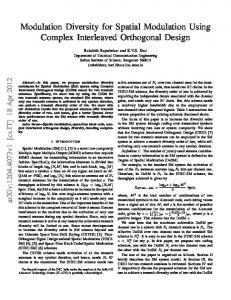
A number of modulation analysis and filtering techniques are described in literature, for example the approaches used in [2, 48, 11, 14]. These approaches first use a filter bank or a short-time Fourier transform, followed by a magnitude or Hilbert envelope to separate the modulator and carrier; then analysis or filtering is performed on the modulator. A problem with these existing methods, as reported by Ghitza [14], is that these modulation filters show considerably less stop-band attenuation than they were designed for. In this section, we propose and assess a method of modulation filtering in which the short-time Fourier transform (STFT) is again used as a filter bank. Instead of taking a subsequent magnitude, coherent demodulation is used, within each sub-band, to separate the modulator and carrier. 3.1 Coherent Modulation Filtering
x(t )
sn (t )
STFT
Coherent Demodulation
e Carrier Freq Detection
x '(t ) Inverse STFT
s 'n (t )
mn (t )
� jIc ( t )
finst (t )
LTI Filtering
Restore Carrier Freq
e
m 'n (t )
jIc ( t )
Figure 1. System for coherent modulation filtering. The thicker lines indicate the time functions are STFT sub-band signals. The superscript prime denotes output signals.
IV - 522
Referring to figure 1, the major and the most important feature distinct from the previous methods is the step of coherent demodulation, which is done independently for every STFT subband. A carrier frequency f inst (t ) is first detected for each subband; then coherent demodulation is performed on each sub-band by multiplying e � jIc ( t ) , where Ic (t ) is the integral of carrier frequency with time,
Ic (t )
³
t
0
f inst (t ) dt .
(9)
If the carrier frequency is constant, this coherent demodulation step simply shifts the sub-band signal down to a low-frequency band. In other words, the carrier frequency detection and coherent demodulation replace the magnitude or Hilbert envelope used within the previous definitions. To complete the coherent modulation filtering system an LTI filter is applied on each sub-band signal followed by restoring the carrier and then combining sub-bands via an inverse STFT. As will be shown below, all three desirable properties, as discussed in Section 2.2, are satisfied by this system. 3.2 Satisfaction of the Properties
In the worst case, where the carrier frequency of a modulation component sits right at the boundary of two sub-bands, the strength of the carrier frequency becomes zero and will be misdetected. But this sub-component only contributes relatively small energy to the reconstructed signal. Other sub-components in neighbor sub-bands contribute the bulk of the energy to the reconstruction. A demonstration of this worst case is shown in figure 2b, where the sub-band has a bandwidth of 400 Hz with 75% frequency overlap. The carrier frequency is 2200 Hz, which sites right at the boundary of two sub-bands. As it is shown, 40 dB suppression is achieved, while the filter is designed for 60 dB suppression, for low-pass modulation filtering, Although this is not perfect, 40 dB suppression in modulation is well beyond human auditory perception [3]. 3. Linear-time shift invariant for modulator property. Since the filtering step in figure 1 is LTI, the LTI property is easily satisfied for the modulator. An illustration of this property is shown in figure 2c. However it should be noted that proper window overlap in the STFT, needs to be chosen to avoid aliasing in sub-bands. For example, 75% overlap is needed for a Hann window.
1. Superposition property. As stated in section 2, this property depends on appropriate filter bank design. Superposition is achieved by adjusting the width of sub-bands, so that there is no more than one modulation component within one sub-band. Note frequency overlap of the filter bank is allowed. For example, for a speech signal, the pitch and its harmonics can be assumed to be distinct carriers. In this case, the sub-band width should be no larger than pitch frequency. A demonstration of the superposition property for a synthetic signal is shown in figure 2a. 2. Frequency shift invariant property. For a single component modulation signal, this property can be easily satisfied, since most IF estimation methods are frequency-shift invariant. In order to keep the superposition property for multiple components signals, we have to use a filter bank to break a signal into subband signals. This inevitably increases the difficulty of carrier frequency detection. In particular, when a carrier frequency is located near the boundary of two sub-bands, the carrier frequency tends to be misdetected. This misdetection problem can largely be solved by using a filter bank with overlapped sub-bands. For example, in our test implementation, an overlapping Hann window was applied within the STFT, resulting in 75% overlap in frequency between consecutive sub-bands. Each carrier component will appear in the main lobes of 4 sub-bands. Assuming the carrier frequency can be correctly detected, one modulated component will be decomposed, by the overlapping STFT, into 4 sub-components 4
s (t )
c(t )m(t )
¦ c(t )m (t ) .
(10)
i
i 1
The LTI property for the modulator, detailed below, guarantees that filtering on the sub-components in (10) yields the same result as filtering on the whole, namely
L ^s(t )` c(t )T ^m(t )`
4
¦ T ^m (t )` c(t ) i
i 1
4 ½ c(t )T ®¦ mi (t ) ¾ c(t )T ^m(t )` ¯i 1 ¿
(11)
Figure 2. Examples of property satisfaction. In all three panels, solid lines show inputs and dashed lines show modulation filtered outputs. (a) Test of the superposition property. Modulation component 1 consists of a 2120 Hz carrier and a 15 Hz modulator; component 2 consists of a 3170 Hz carrier and a 40 Hz modulator. A low-pass modulation filter at 30 Hz is applied on all sub-band signals. More than 60 dB suppression is achieved for the second component. (b) Test of the frequencyshift invariant property. The input signal consists of a 2200 Hz carrier, which falls at a boundary of two sub-bands, with a 25 Hz modulator. Low-pass modulation filtering is performed at 15 Hz and about 40dB suppression is achieved (c) Test of the modulator linear time-shift invariant property. The input signal consists of a 2120 Hz carrier and two sine wave modulators at 15 and 40 Hz. Low-pass modulation filtering is performed at 30 Hz and about 60 dB suppression is achieved for the 40 Hz modulator.
IV - 523
4. EXAMPLE
We applied our coherent modulation filtering method to a speech signal. As shown in figure 3a, a segment of speech signal has a pitch frequency of about 100 Hz. To keep the superposition property, the STFT had sub-band width of 100 Hz with 75% overlap between consecutive sub-bands. Thus the modulation frequency range is from -50 to 50 Hz. A time-varying IF was estimated in each sub-band, corresponding to the time-varying pitch frequency. Note that the speech segment in figure 3a evolves in time between three different voiced sounds. Extreme low-pass output (figure 3b) from the proposed coherent modulation filtering method yields a flat envelope and equalizes the difference for the three voiced segments as desired; while the low-pass from the incoherent method [4] does not produce an flat envelope and produces distortion in the fine structure (figure 3c). Similar problems are seen for other previous incoherent techniques.
Figure 3. Example of modulation filtering on speech. (a) The original speech signal; (b) Output of a low-pass modulation filter (coherent method) with 1.4 Hz corner; (c) Output of a low-pass modulation filter (incoherent method) with 1.4 Hz corner.
The above modulation low-pass effect seen on speech demonstrates that new types of predictable signal modifications are indeed possible with modulation filters.
5. CONCLUSION
We have defined three necessary properties for modulation filtering systems. Any modulation filtering method satisfying these three properties will potentially yield effective and distortion-free filtering results. We also implemented a new modulation filtering method, applicable to broadband signals, using a fixed STFT as a filter bank and coherent demodulation as a detection operation within each sub-band. It has been shown that the new method is able to satisfy all three properties. The preliminary test on a speech signal confirms the accuracy of this coherent approach.
Accurate modulation filters, when designed for particular applications, offer new approaches for signal separation and noise reduction. Signals which overlap heavily in standard Fourier frequency often differ in modulation frequency extent. With accurate modulation filtering, these differences could be used as a basis for modulation frequency enhancement of the desired signal or for other signal modifications. This work was supported by the Office of Naval Research. We acknowledge helpful conversations with Dr. Bishnu Atal and Steven Schimmel of the University of Washington.
6. REFERENCES
[1] R. McEachern, "How the ear really works," in Proceedings of the IEEE-SP International Symposium,Time-Frequency and Time-Scale Analysis, Victoria, BC, Canada, 1992. [2] Z. M. Smith, B. Delgutte, and A. J. Oxenham, "Chimaeric sounds reveal dichotomies in auditory perception," Nature, 416, pp. 87-90, 2002. [3] B. C. J. Moore, "Masking in the human auditory system," in Collected Papers on Digital Audio Bit-Rate Reduction, N. Gilchrist and C. Grewin, Eds., 1996, pp. 9-19. [4] L. E. Atlas and M. S. Vinton, "Modulation frequency and efficient audio coding," in Proceedings of the SPIE, 2001. [5] J. K. Thompson and L. E. Atlas, "A Non-Uniform Modulation Transform for Audio Coding with Increased Time Resolution," in Proceedings of IEEE ICASSP, Hong Kong, 2003. [6] S. Greenberg and B. E. D. Kingsbury, "The modulation spectrogram: in pursuit of an invariant representation of speech," in Proceedings of the IEEE ICASSP, 1997. [7] R. Drullman, J. Festen, and R. Plomp, "Effect of temporal envelope smearing on speech reception," J. Acoust. Soc. Am., 95, pp. 1053-1064, 1994. [8] T. Arai, M. Pavel, H. Hermansky, and C. Avendano, "Intelligibility of speech with filtered time trajectories of spectral envelopes," in Proceedings of the ICSLP, 1996. [9] L. E. Atlas, Q. Li, and J. K. Thompson, "Homomorphic Modulation Spectra," in Proceedings of the IEEE ICASSP, Montreal, Canada, 2004. [10] Q. Li and L. Atlas, "Over-Modulated AM-FM Decomposition," in Proceedings of the SPIE, Denver, 2004. [11] A. Rao and R. Kumaresan, "On decomposing speech into modulated components," IEEE Transactions on Speech and Audio Processing, 8, pp. 240-54, 2000. [12] T. F. Quatieri, T. E. Hanna, and G. C. O'Leary, "AM-FM separation using auditory-motivated filters," IEEE Transactions on Speech and Audio Processing, 5, pp. 465-80, 1997. [13] P. J. Loughlin and B. Tacer, "On the amplitude- and frequency-modulation decomposition of signals," Journal of the Acoustical Society of America, 100, pp. 1594-601, 1996. [14] O. Ghitza, "On the upper cutoff frequency of the auditory critical-band envelope detectors in the context of speech perception," Journal of the Acoustical Society of America, 110, pp. 1628-1640, 2001.
IV - 524