International Journal of Fuzzy Logic and Intelligent Systems, vol. 9, no. 4, December 2009 pp. 309-314
Neuro-Fuzzy Control of Inverted Pendulum System for Intelligent Control Education G. H. Lee and S. Jung* Intelligent Systems and Emotional Engineering(ISEE) Lab, BK21 Mechatronics Group, Chungnam National University, Daejeon, Korea 305-764 Abstract This paper presents implementation of the adaptive neuro-fuzzy control method. Control performance of the adaptive neuro-fuzzy control method for a popular inverted pendulum system is evaluated. The inverted pendulum system is designed and built as an education kit for educational purpose for engineering students. The educational kit is specially used for intelligent control education. Control purpose is to satisfy balancing angle and desired trajectory tracking performance. The adaptive neuro-fuzzy controller has the Takagi-Sugeno(T-S) fuzzy structure. Back-propagation algorithm is used for updating weights in the fuzzy control. Control performances of the inverted pendulum system by PID control method and the adaptive neuro-fuzzy control method are compared. Control hardware of a DSP 2812 board is used to achieve the real-time control performance. Experimental studies are conducted to show successful control performances of the inverted pendulum system by the adaptive neuro-fuzzy control method. Key Words: Neuro-fuzzy controller, inverted pendulum, intelligent control education
1. Introduction Recently intelligence becomes quite important terminology in various engineering applications. Intelligent systems include robot systems, Mechatronics systems, and control systems. This leads us to study intelligent algorithms and to educate students. For control engineers, intelligent control method is one of important key subjects for developing intelligent systems. Intelligent control techniques are well developed and used for controlling dynamical systems. Intelligent techniques include neural network, fuzzy logic, reinforcement learning, and genetic algorithm. Neural network and fuzzy logic are used mostly for intelligent control applications since other techniques take time and lack for real time control performance. Neural network is one of powerful tools for learning and adaptation, but it suffers from complex internal network structure. Thus, mathematical analysis of internal processing cannot be described clearly in the network [1-3]. Fuzzy logic is well known for representing human expression. Transforming expression of human intuitions into numerical representation for a low level system can be processed through fuzzy logic [4-6]. However, obtaining optimal fuzzy rules for a typical system is not easy and it requires time-consuming processes of trial and error. Once the Manuscript received Apr. 30, 2009; revised Nov. 25, 2009 *Corresponding author The contents of this paper have been presented in IEEE Conference on Mechatronics and Automation, 2008. This research was financially supported by the Ministry of Education, Science Technology (MEST) and Korea Industrial Technology Foundation (KOTEF) through the Human Resource Training Project for Regional Innovation.
optimal fuzzy rules for the system are found, the fuzzy control process can be easily implemented on the hardware with efficient cost. Genetic algorithm is a good optimization tool for finding optimal solutions through intensive iterative calculation in offline fashion. Genetic algorithm is not suitable for on-line learning and real time control applications. Therefore, a fusion method of two or three techniques together is required and preferred to compensate for defects of each intelligent tool to have the better performance. A well known combination of two tools is a combined controller of neural network and fuzzy logic. It is called a neuro-fuzzy controller that has the neural network structure whose internal function represents the fuzzy logic. Internal weights of neural network are adaptively adjusted in the way of minimizing errors by changing fuzzy rules to satisfy the specified performance. Indeed, the neuro-fuzzy control structure has advantages of both neural network and fuzzy logic[6-11]. In the framework of the adaptive neuro-fuzzy control approach, the most important concern is to develop the learning algorithm to minimize the objective function. In this paper, among many types of neuro-fuzzy control structures, the Takagi-Sugeno (T-S)neuro-fuzzy control structure is used for simple derivation of the back-propagation algorithm. The inverted pendulum system built inside the intelligent control educational kit is used as a testbed. Empirical works of controlling the inverted pendulum system by the adaptive neuro-fuzzy controller are conducted to test the performance of the controller. The inverted pendulum system has typical characteristic and evolved to various challenging types [12-16]. To achieve real-time control, a DSP 2812 board is used for the fast calculation of the backpropagation learning algorithm derived for the adaptive neurofuzzy control network. Performances of the PID control method and the adaptive neuro-fuzzy control method for balancing the
309
International Journal of Fuzzy Logic and Intelligent Systems, vol. 9, no. 4, December 2009
pendulum under disturbances are compared to evaluate the controller performance.
j j Rule j : if e i is A 1 and if Δ e i is B 1 then
y
2. Adaptive Neuro-Fuzzy Control
where
= p 1j e 1 + q 1j Δ e 1 + r1 j
j
A 1 j and B 1 j
are fuzzy sets whose shapes are
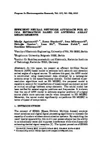
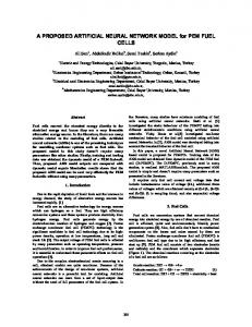
Gaussian functions and p 1j , q 1j , r1 j are weights which can be The adaptive neuro-fuzzy control structure is similar to the neural network whose function is fuzzy logic such that fuzzy rules can be changed with respect to uncertainties in the system. The adaptive neuro-fuzzy controller is getting popular since it takes benefits from merits of both neural network and fuzzy logic. To embed fuzzy logic into the multi-layered neural network, it takes more than 3 layers to process defuzzification, inference, and fuzzification procedures to complete the fuzzy controller. Fig.1 shows the general adaptive neuro-fuzzy structure consisting of 5 layers. Layer 1 takes crisp input values and layer 2 calculates the membership function. Layer 3 represents fuzzy rules. Each node performs the AND operation. Layer 4 performs the inference process by doing OR operation. Finally, layer 5 conducts the defuzzification process. Parameters in layer 2 and 4 are updated adaptively due to error minimization methods.
changed with respect to the condition. The difference from Fig. 1 is the resultant part of if-fuzzy rules which is linear. This makes the adaptation process for the parameters of the resultant part easier by applying the back-propagation algorithm. The function of each layer can be explained as below. 1) Layer 1 calculates the membership function values of inputs. μ G = G i j ( x i , m ij , σ ij ) = exp( − (
x i − m ij
σ
j
i
2 j
)2 )
(1)
where x i is the ith input, m ij is the center value of the jth unit of layer 2, and σ
ij
is the width of the jth unit of layer 2
for the ith input. Fig. 3 shows the typical 5 fuzzy sets. 2)Layer 2 produces the products of all the membership values. w
j
=
N
∏
μ
i=1
G 1
j
μ
G 2
Λ
j
μ
j G N
(2)
3) Layer 3 normalizes the output of layer 2. w
where b =
j
=
wj
(3)
b
M
∑
j =1
wj .
4) Layer 4 calculates the linear output.
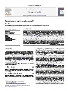
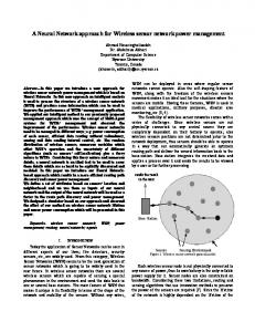
f where Fig. 1 Adaptive neuro-fuzzy structure It is true that the adaptive law is seldom obtained for the Mamdani fuzzy rule method shown in Fig 1. The linearized output representation makes the system be updated with ease by applying the back-propagation algorithm. This yields the simplified version of the adaptive neuro-fuzzy network called the Takagi-Sugeno neuro-fuzzy network structure as shown in Fig.2. The difference is that the resultant part of if rules is linear.
y
j
j
= yjw
j
= p j e + q j Δ e + r j and
(4)
p j , q j , rj
variables to be updated. 5) Layer 5 sums all outputs f j . f output =
M
∑
j =1
fj
3. T-S Neuro-fuzzy Control Scheme 3.1 Process of T-S Neuro-Fuzzy Structure The T-S neuro-fuzzy structure for the control purpose is shown in Fig.2. It takes output errors as inputs and has 5 layers to process the fuzzy algorithm. The fuzzy rule for the T-S network is described as
310
are
Fig. 2 T-S Neuro-fuzzy control structure
(5)
Neuro-Fuzzy Control of Inverted Pendulum System for Intelligent Control Education
Fig. 4 shows the 5 fuzzy sets which can be described as the Gaussian function. The same fuzzy sets are used for the error and the change of the error.
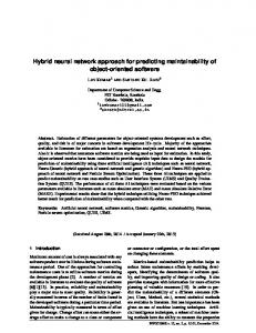
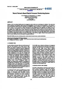
Fig. 4 Neuro-fuzzy control block diagram The pendulum angle error is defined as Fig. 3 Fuzzy membership function
eθ = θ d − θ ,
3.2 Backward Process of T-S Neuro-Fuzzy Structure The backward process is the back-propagation algorithm to update parameters. We have 5 variables to update, three for the linear output and two for the Gaussian functions. The output error is designed as
e = fd − f ,
(6)
where f d is the desired output and f is the actual output of the network. The gradient of each parameter is described as
w
Δrj = η re Δq Δp
j
j
w
= η pe
w
j
b
Δ m ij = 2η m e
Δσ
ij
= 2η σ e
desired angle is set to zero. The position error is defined as
ex = xd − x , where x d
is the desired position and x
(9) is the actual
position of the cart. The control input to the system is added together.
τ = τθ +τ x .
(10)
x2
b j
where θ d is the desired angle and θ is the actual angle. The
We expect the coupling action between the angle controller and the position controller which can be managed by the neurofuzzy controller.
j
b
= η qe
(8)
5. Experimental Studies (7)
x1
y
j
b y b
j
( x i − m ij )
σ
2 ij
( x i − m ij ) 2
σ
3 ij
N
∏ [exp(
−
i =1
N
∏ [exp( i =1
−
( x i − m ij ) 2
σ
2 ij
( x i − m ij ) 2
σ
2 ij
)]
)]
where η r , η q , η p , η m , η σ are learning rates and the inputs are x 1 = e , x 2 = Δ e in this controller.
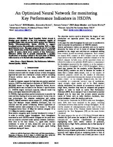
5.1 Experimental Setup Fig. 5 shows the overall inverted pendulum system kit for the educational purpose. The system consists of the pendulum, neuro-fuzzy control hardware, and a power system. The movement of the cart and the pendulum can be measured by encoders. Fig. 6 shows the block diagram of the overall system shown in Fig. 5.
4. Inverted Pendulum Control Scheme The T-S neuro-fuzzy control structure for the inverted pendulum system is shown in Fig. 4. Two neuro-fuzzy controllers are used separately, one for the pendulum angle control and another for the cart position control. Each neurofuzzy controller has the same structure shown in Fig. 2. We can expect that the controller output cannot guarantee the stability of the system at the beginning if internal weight values of the neuro-fuzzy controller are randomly selected.
Fig. 5 Overall system setup
311
International Journal of Fuzzy Logic and Intelligent Systems, vol. 9, no. 4, December 2009
Fig. 6 Overall system block diagram Control hardware of DSP and FPGA is shown in Fig. 7. The corresponding block diagram of the hardware system is shown in Fig. 8. The neuro-fuzzy control algorithm is embedded on a DSP 2812 board that communicates with the FPGA module. The FPGA module includes encoder counters and PWM generators.
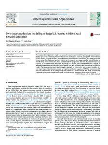
important for determining the absolute reference value for controlling the pendulum. Initial weight parameters for the neuro-fuzzy controller are randomly selected with a small magnitude less than 0.001. Initially, the pendulum is held by hands to stabilize the system since the initial control action by the neuro-fuzzy controller cannot stabilize the system with randomly selected weight values. Without holding the pendulum at the beginning may result in falling down. Thus, the randomly selected parameter values are not suitable to control and cause the instability of the system. This initial stability is a major defect of the neurofuzzy control method. Fig. 9 shows the pendulum angle error. The corresponding position error is shown in Fig. 10. Although there are large errors at the beginning, the neuro-fuzzy controller adapts parameters quickly so that the error decreases after 2 seconds. This means that newly designed fuzzy rules after 2 seconds works for controlling the pendulum system. 0.25 0.2 0.15
angle error(rad)
0.1 0.05 0 -0.05 -0.1 -0.15 -0.2
0
2
4
6
8
10 12 time(sec)
14
16
18
20
Fig. 9 Angle error of the pendulum for balancing 0.08 0.06
Fig. 7 DSP6713 + FPGA Based ICEK position error(m)
0.04 0.02 0 -0.02 -0.04 -0.06 -0.08
0
2
4
6
8
10 12 time(sec)
14
16
18
20
Fig. 10 Position error for balancing Fig. 8 Control system block diagram 5.2 Balancing task with randomly selected parameters First, the balancing control task of the inverted pendulum system is conducted. Initially the pendulum is set to zero position by positioning down and then positioned at upright position. Setting the zero angle position accurately is quite
312
5.3 Balancing task with pre-learned parameters Next test is to use pre-learned parameter values of the adaptive neuro-fuzzy controller to stabilize the system at the beginning. Figures 11 and 12 show the balancing results of the neuro-fuzzy controller. We clearly see that the errors are quite small at the beginning. The system is stable at the beginning of the control action as well. Convergence of errors becomes faster.
Neuro-Fuzzy Control of Inverted Pendulum System for Intelligent Control Education
0.01 0.18 0.16
0.005
position error(m)
0.14
angle error(rad)
0
-0.005
0.12 0.1 0.08 0.06 0.04
-0.01 0.02 0
-0.015 -0.02
-0.02
0
2
4
6
8
10 12 time(sec)
14
16
18
20
Fig. 11 Angle error of the pendulum for balancing with learned parameters 0.08 0.06
position error(m)
0.04 0.02 0 -0.02 -0.04 -0.06 -0.08
0
2
4
6
8
10 12 time(sec)
14
16
18
0
2
4
6
8
10 12 time(sec)
14
16
18
20
Fig. 14 Position error for balancing with disturbances 5.5 Comparison of balancing task between PID control method and neuro-fuzzy control method Fig. 15 shows the resulting plot of PID control performance plotted inside the GUI design. GUI panel is designed such that it has many icons to select control parameters for different control methods. Here, performances of two control methods are compared. We clearly see that sinusoidal trajectory tracking performance by the PID control method shows the oscillatory behavior although the system follows the desired trajectory. However, in Fig. 16, the performance of the neuro-fuzzy control method shows the less oscillatory behavior and quite stable performance. Thus tracking performance of inverted pendulum system by the adaptive neuro-fuzzy controller is much better than that of the PID control method.
20
Fig. 12 Position error for balancing with learned parameters 5.4 Balancing task under disturbances Next experiment is to test the robustness of the controller. Several intentional hits are impacted to the pendulum while it maintains balance. As seen in Fig. 13, the angle error becomes large when an impact applies to the pendulum. The stronger the impact is, the larger the error occurs. However, the controller is robust enough to maintain balance under several impacts. The corresponding position error is plotted in Fig. 14. Fig. 15 Tracking performance by PID control
0.12 0.1
angle error(rad)
0.08 0.06 0.04 0.02 0 -0.02 -0.04
0
2
4
6
8
10 12 time(sec)
14
16
18
Fig. 13 Angle error for balancing with disturbances
20
Fig. 16 Tracking performance by neuro -fuzzy control
313
International Journal of Fuzzy Logic and Intelligent Systems, vol. 9, no. 4, December 2009
6. Conclusion The neuro-fuzzy controller has been implemented on the DSP chip and tested for balancing the inverted pendulum system mounted on the educational kit. Learning algorithm has been derived for on-line learning and control. Experimental results show that the initialization of parameters of the neurofuzzy controller plays a very important role to stabilize the system at the beginning. At the beginning of the experiment, the system was unstable with the neuro-fuzzy controller since the output of the neuro-fuzzy controller cannot be expected. Thus, the next research topic is to study the robust control algorithm for the neuro-fuzzy controller to stabilize the system at the beginning of the control action.
References [1] S. Omatu, T. Fujinaka, and M. Yoshioka, “Neuro-pid control for inverted single and double pendulums,” IEEE Conf. On Systems, Man, and Cybernetics, pp. 8-11, 2000. [2] S. Jung, H. T. Cho, and T. C. Hsia, "Neural network control for position tracking of a two axis inverted pendulum system: Experimental studies,” IEEE Trans. on Neural Network, vol. 18, no. 4, pp. 1042-1048, 2007. [3] S. Jung and S. S. Kim, "Hardware implementation of a neural network controller with a DSP an FPGA for nonlinear systems”,,” IEEE Trans. on Industrial Electronics, vol. 54, no. 1, pp. 265-271, 2007. [4] T. H. Hung, M. F. Yeh, and H. C. Lu, “A PI-like fuzzy controller implementation for the inverted pendulum system,” Proc. of IEEE Conference on Intelligent Processing Systems, pp. 218-222, 1997. [5] M. E. Magana, and F. Holzapfel, “Fuzzy-logic control of an inverted pendulum with vision feedback,” IEEE Trans. on Education, vol. 41, no. 2, pp. 165-170, 1998. [6] F. Cheng, G. Zhong, Y Li, and Z. Xu, “Fuzzy control of a double inverted pendulum”, Fuzzy sets and systems, vol.79, pp. 315-321, 1996. [7] L. Peng and P. Y. Woo, “Neural-fuzzy control system for robotic manipulators”, IEEE Control Systems Magazine, pp. 53-63, vol. 22, no. 1, 2002. [8] S. Pletl, “Neuro-fuzzy control of rigid and flexible joint robotic manipulator”, IEEE IECON, pp. 93-97, 1995. [9] P. H. Yang, D. M Auslander, and R. N. Dave, ‘Real time neuro-fuzzy control of a nonlinear dynamic system”, North American Fuzzy Information Processing, pp. 210-214, 1996. [10] W. Wei, S. Zeng, and X. Gan, “Fuzzy and neural network control system of intelligent RLED arm manipulators for dynamic obstacles”, IEEE Conf. on Fuzzy Systems, pp. 577580, 2001. [11] J. S. Wang and C. S. Lee, “Self-adaptive recurrent neuro-fuzzy
314
control of an autonomous underwater vehicle”, IEEE Trans. on Robotics and Automations, vol. 19, no. 2, pp. 283-295, 2003. [12] M. W. Spong, P. Corke, and R. Lozano, “Nonlinear control of the inertia wheel pendulum”, Automatica, vol. 37, pp. 18451851, 2001. [13]M. W. Spong, “The swing up control problem for the acrobat”, IEEE Control Systems Magazine, vol. 15, pp. 72-79, 1995. [14] W. White and R. Fales, “Control of double inverted pendulum with hydraulic actuation : a case study”, Proc. Of the American Control Conference, pp. 495-499, 1999. [15] H. Fer and D. Enns, “An application of dynamic inversion to stabilization of a triple inverted pendulum on a cart”, IEEE Conf. on Control Applications, pp. 708-714, 1996. [16] J. Shen, A. K. Samyal, N. Chaturvedi, D. Bernstein, and H. McClamroch, “Dynamics and control of a 3 D pendulum”, IEEE Conf. on Decision and Control, 2004.
Geun Hyung Lee He received his B.S. degree in Control and Measurement Engineering from Gyungil University in 2006, and he graduated from Mechatronics Engineering, Chungnam National University in 2009. His research interests are intelligent control applications, control hardware design, and DSP systems. Phone Fax Email
: +8242-821-7232 : +82-42-823-4919 :
[email protected]
Seul Jung He received his B.S. degree in Electrical & Computer Engineering from Wayne State University in 1988, and his M.S. and Ph.D. degrees in Electrical & Computer Engineering from the University of California, Davis in 1991 and 1996, respectively. He joined the Department of Mechatronics Engineering, Chungnam National University in 1997, where he is presently a professor. His research interests include intelligent control systems, hardware implementation of intelligent controllers, robot education, and intelligent robotic systems. He is a member of Tau Beta Pi and Eta Kappa Nu. Now he is serving as a general secretary of Asian Control Association(ACA). Phone Fax Email
: +8242-821-6876 : +82-42-823-4919 :
[email protected]