Providing Full QoS Support in Clusters Using Only Two VCs at the Switches? A. Mart´ınez1 , F. J. Alfaro1 , J. L. S´anchez1 , and J. Duato2 1
2
Departamento de Inform´ atica, Escuela Polit´ecnica Superior Universidad de Castilla-La Mancha, 02071 - Albacete, Spain {alejandro,falfaro,jsanchez}@info-ab.uclm.es Dept. de Inform´ atica de Sistemas y Computadores, Facultad de Inform´ atica Universidad Polit´ecnica de Valencia, 46071 - Valencia, Spain
[email protected]
Abstract. Current interconnect standards providing hardware support for quality of service (QoS) consider up to 16 virtual channels (VCs) for this purpose. However, most implementations do not offer so many VCs because they increase the complexity of the switch and the scheduling delays. In this paper, we show that this number of VCs can be significantly reduced. Some of the scheduling decisions made at network interfaces can be easily reused at switches without significantly altering the global behavior. Specifically, we show that it is enough to use two VCs for QoS purposes at each switch port, thereby simplifying the design and reducing its cost.
1
Introduction
The last decade has witnessed a vast increase in the variety of computing devices as well as in the number of users of those devices. In addition to the traditional desktop and laptop computers, new handheld devices like pocket PCs, PDAs, and multimedia cellular phones have now become household names. The main reasons for the widespread use of computing devices are the availability of cheaper and more powerful devices and, even more importantly, the huge amount of information and services available through the Internet. These services rely on applications executed in many servers all around the world. Clusters of PCs have emerged as a cost-effective platform to implement these services and run the required Internet applications. These clusters provide service to thousands or tens of thousands of concurrent users. Many of these applications are multimedia applications, which usually present bandwidth and/or latency requirements [1]. These are known as QoS requirements. In the next section, we will be looking at some of the proposals to provide QoS in clusters and system area networks. Most of them incorporate 16 or even ?
This work was partly supported by the Spanish CICYT under grant TIC2003-08154C06, Junta de Comunidades de Castilla-La Mancha under grant PBC-05-005-1, and by the Spanish State Secretariat of Education and Universities under FPU grant.
more VCs, devoting a different VC to each traffic class. This increases the switch complexity and also prevents the use of these VCs for other purposes (for instance, to provide adaptive routing or fault tolerance). Moreover, it seems that, when the technology enables it, the trend is to increase the number of ports instead of increasing the number of VCs per port [2]. In the recent switch designs, the buffers at the ports are implemented with a memory space organized in logical queues. These queues consist in linked lists of packets, with pointers to manage them. Our experience with communications’ hardware manufacturers [3] has taught us that the complexity of the switch and the scheduling delays heavily depend on the number of queues at the ports. VCs, which can be used for many purposes, are implemented as queues of this kind. Then, a reduction of the number of VCs necessary to support QoS can be very helpful in the switch design. In this paper, we show that it is enough to use two VCs at each switch port for the provision of QoS. One of these VCs is used for QoS traffic and the other one for best-effort traffic. Although this is not a new idea, the novelty of our proposal lies in the fact that the global behavior of the network is very similar as if it had much more VCs. This can be achieved by reusing in the switches some of the scheduling decisions made at network interfaces. Simulation results show that applications achieve an adequate QoS performance, but with a reduced processing delay and using fewer VCs, which results in less chip area. The remainder of this paper is structured as follows. In the following section the related work is presented. In Section 3 we present our strategy to reduce the number of VCs required for QoS support. Details on the experimental platform and the performance evaluation are presented in Section 4. Finally, Section 5 summarizes the results of this study and identifies directions for future research.
2
Related Work
During the last decade several switch designs with QoS support have been proposed. All of them incorporate VCs in order to provide QoS support. In these proposals, different scheduling algorithms are used to arbitrate between the different existing traffic flows, providing each one with QoS according to its requirements. The Multimedia Router (MMR) [4] is a hybrid router. It uses pipelined circuit switching for multimedia traffic and virtual cut-through for best-effort traffic. Pipelined circuit switching is connection-oriented and needs one VC per connection. This is the main drawback of the proposal because the number of VCs per physical link is limited by the available buffer size and there may not be enough VCs for all the possible existing connections. Therefore, the number of multimedia flows allowed is limited by the number of VCs. Moreover, the scheduling among hundreds of VCs is a complex task. MediaWorm [5] was proposed to provide QoS in a wormhole router. It uses a refined version of the Virtual Clock algorithm [6] to schedule the existing VCs. These VCs are divided into two groups: One for best-effort traffic and the other
for real-time traffic. Several flows can share a VC, but 16 VCs are still needed to provide QoS. Besides, it is well known that wormhole is more likely to produce congestion than virtual cut-through. In [7], the authors propose a preemption mechanism to enhance MediaWorm performance, but in our view that is a rather complex solution. InfiniBand was proposed in 1999 by the most important IT companies to provide present and future server systems with the required levels of reliability, availability, performance, scalability and QoS [8]. Specifically, the InfiniBand Architecture (IBA) proposes three main mechanisms to provide the applications with QoS. These are traffic segregation with service levels, the use of VCs (IBA ports can have up to 16 VCs) and the arbitration at output ports according to an arbitration table. Although IBA does not specify how these mechanisms should be used, some proposals have been made to provide applications with QoS in InfiniBand networks [9]. Finally, PCI Express Advanced Switching (AS) architecture is the natural evolution of the traditional PCI bus [10]. It defines a switch fabric architecture that supports high availability, performance, reliability and QoS. AS ports incorporate up to 20 VCs that are scheduled according to some QoS criteria. In the AS specifications, three possible arbiters are proposed, one of them being table-based. All the proposals studied use a significant number of VCs to provide QoS support. If a great number of VCs is implemented, it would require a significant fraction of chip area and would make packet processing a more time-consuming task. Moreover, in all the cases, the VCs are used to segregate the different traffic classes. Therefore, it is not possible to use the available VCs to provide other functionalities like adaptive routing or fault tolerance when all the VCs are used to provide QoS support. On the other hand, there have been proposals which use only two VCs. For instance, the Avici TSR [11] is a well-known example of this. It is able to segregate premium traffic from regular traffic. However, it is limited to this classification and cannot differentiate among more categories. In the recent IEEE standards, it is recommended to consider seven traffic classes [12]. So, although being able to differentiate two categories is a big improvement, it could be insufficient. In contrast, the novelty of our proposal lies in that although we use only two VCs in the switches, the global behavior of the network is very similar as if the switches were using much more VCs. This is because we are reusing at the switch ports the scheduling decisions performed at the network interfaces, which have as many VCs as traffic classes. In the end, the network provides a differentiated service to all the traffic classes considered. To the best of our knowledge, only Katevenis and his group [13] have proposed something similar before. The basic idea of their architecture is to map the multiple priority levels onto the two existing queues, for each crosspoint buffer. The operation of the system is analogous to a two-lane highway, where cars drive in one lane and overtake using the other. However, this proposal is complex because it needs specific hardware and signaling. Furthermore, it is more limited
in its scope than ours, because it is aimed to a single-stage router based on a single buffered crossbar. This crossbar has small buffers at the crosspoints that the authors split into two VCs. In contrast, our proposal is a simpler and more general technique, as we will see in the next section.
3
Reducing the Number of VCs for QoS Support
In this section, we present our proposal for QoS provision with reduced resources. The basic idea consists in using only two VCs at the switch ports. One of these VCs would be used for QoS packets and the other for best-effort packets. We reuse at switches the scheduling decisions performed at network interfaces. This allows us to achieve a performance similar to that obtained by systems with much more VCs.
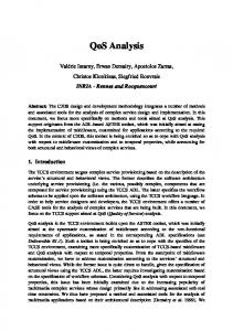
Fig. 1. QoS support at the network interface and the switch.
Figure 1 shows an example of a network interface that is connected to a switch. Note that at both the network interface and the switch input port, there are several VCs. When a packet arrives at the switch, the header is analyzed and the packet is then usually stored in a VC according to the flow or class to which it belongs to. However, packets arriving at the switch have been previously sorted by the network interface according to some criteria. If we separate the packets in different VCs, we are losing this order, which may contain enough information to simplify the scheduling at the switch. However, it is not enough to put all the packets in the same VC to reuse the scheduling decisions. It is also necessary that the arbiter implementing this technique considers the global priority level of the packets, as opposed to the traditional 2 VC design, which would only consider two categories: premium and regular. In order for our proposal to be effective we need two assumptions. The first assumption we make is that a static priority criterion exists to order packets. In this way, every packet would be stamped with a priority level. This is necessary because we will maintain the incoming order along the whole network. This is not a big deal because queuing delays for QoS traffic will be short, and therefore, the
packet ordering established at network interfaces does not need to be changed at any switch in the path. The second assumption is that there must be a connection admission control (CAC) for the traffic with QoS requirements so that no link is oversubscribed by QoS traffic. This requirement is needed to provide bandwidth guarantees and avoid starvation of the QoS traffic. The CAC is also necessary to assure that this kind of traffic will flow with short delays. Note that although we assume that QoS traffic does not oversubscribe any link, no assumption is made about best-effort traffic. Thus, if we did not separate QoS traffic and best-effort traffic, the total bandwidth demand for a given output link could exceed the available bandwidth. For this reason, we cannot use just one VC, and therefore we propose to use two VCs at the switches. It is important to note that the order of the different best-effort traffic classes is also kept with this design. Although we use only one VC for best-effort traffic, we also consider the different priorities of packets belonging to this group. This means that the switch will also differentiate among this kind of packets, as we will see in the next section. Now, we will proceed to describe in depth how our proposal works. Let us suppose that several packets arrive at a switch from a network interface. Taking into account that the interface implements a priority-based arbiter, the first packet should be the one with the highest priority. So, instead of separating the packets among several VCs according to their traffic classes, we put them all in the same queue in the arrival order. Later, when the switch must decide which packets should be transmitted, it will seek in the input queues. It is only necessary to look at the first packet in each queue, because its position at the front of the queue indicates that it had a higher priority when it left the network interface. Obviously, the network interface can only arbitrate among the packets it holds at a given moment. Therefore, when no more high-priority packets are available, a low-priority QoS packet can be transmitted. If this packet has to wait at a switch input queue, and other packets with higher priority are transmitted from the network interface, they would be stored in the same VC as the lowpriority packet, and be placed after it in the queue. Thus, the arbiter would penalize the high-priority packets, because they would have to wait until the low-priority packet is transmitted. But this situation, which we call order error, has a small impact on performance because there is bandwidth reservation for QoS packets. This means that all the QoS packets will flow with short delay. In the performance evaluation section, we will see that the order errors have a low impact on the performance. However, they make latency and jitter more variable. Although the average value will remain similar, peak values will be increased slightly. The other main limitation of this technique is the necessity of a CAC, which is not always possible or practical. However, most of the recent interconnect proposals (InfiniBand or AS) include a CAC in their specification.
4
Performance Evaluation
In this section, we show the behavior of our proposal and we compare it with the performance of traditional switches. First, we will explain the simulated network architecture. Next, we will give details on the parameters of the network and the load used for the evaluation. Finally, we present and comment the results. 4.1
Simulated architecture
Our objective is to evaluate the performance of our technique under fair conditions. In order to achieve this, we will define a complete network architecture, including all the elements necessary to work. However, many of them are not directly related with our work. We do not aim at achieving the best performance or proposing a whole new switch design, but, instead, we aim at defining a fair scenario in which compare several switch architectures. For that reason, we have not used state-of-the-art routing techniques, congestion control mechanisms, etc. We have used the most popular and well-known solutions for these issues. The network used to test the proposals is a perfect-shuffle multi-stage interconnection network (MIN) with 64 end-points. We have chosen a MIN because it is a usual topology for clusters. However, our proposal is valid for any network topology, including both direct networks and MINs. The switches use a combined input and output buffer architecture, with a crossbar to connect the buffers. No packets are dropped because we use credit-based flow control. The parameters of the network elements used in this performance study are given in Table 1. Note that we are assuming some internal speed-up (×1.5), as it is usually the case in most commercial switches. Table 1. Simulation parameters. Switch ports 8 Packet size 64 to 2048 bytes Packet header size 8 bytes Control message size 8 bytes Crossbar scheduling time 20/10 ns
Port buffer size 32 Kbytes Channel bandwidth 2 Gb/s Crossbar bandwidth 3 Gb/s Network interfaces 64 Output scheduling time 10/5 ns
Virtual output queuing (VOQ) is implemented to solve the head-of-line blocking problem at the switch level. However, this does not increase the necessary buffer memory, only the crossbar scheduling time. Note that, nowadays, the queues are implemented logically over a shared space. That means that adding more queues implies more pointers and more complex arbiters, but not more buffer space. Furthermore, most of current commercial switches include VOQ as the technique to minimize the effects of head-of-line blocking. In Table 1 we also show the amount of memory at each port. It is the minimum necessary space to achieve the peak throughput. Taking into account that
there is credit-based flow control and we are using Virtual Cut-Through switching, it would be necessary a space at each VC of one maximum packet size plus one round-trip-time. However, since it is common to use maximum packet size, we round the number up, resulting in two whole packets, which results in 4 Kbytes for each VC. Note that switches using our proposal save memory (and thus chip area) at the ports by a factor of 4 compared with the 8 VC case. The scheduling delays have been chosen to reflect the actual delays in real implementations and the use of fewer VCs with our proposal. We have considered the research in the area, like Peh’s work [14], which indicates that the arbitration time is logarithmic in the number of VCs. In Table 1, the number before the slash is the delay for 8 VC switches and the number after the slash is the delay for 2 VC switches (both traditional and using our technique). Therefore, we obtain a speed-up of 2.0 using our proposal. The CAC we have implemented is a simple one, based on average bandwidth. Each connection is assigned a path where enough resources are assured. We also use a load balancing mechanism, which consists in assigning the least occupied route among those possible. There exist more complex and powerful mechanisms, but this is enough to test our proposal. 4.2
Traffic model
In Table 2 the characteristics of the traffic injected in the network are included. We have considered the traffic classes (TCs) defined by the IEEE standard 802.1D-2004 [12] at the Annex G, which are particularly appropriate for this study. However, we have added an eighth TC, Preferential Best-effort, with a priority between Excellent-effort and Best-effort. In this way, the workload is composed of 8 different TCs. Each TC has decreasing priority, such that TC 7 has the highest priority and TC 0 has the lowest. The proportion of each category has been chosen to provide meaningful results. Our intention is to put the network in a situation where the different TCs have to compete for limited resources. We also want to have diversity between the sources, combining different packet sizes and different traffic distributions, that is, constant bit rate (CBR) flows combined with variable bit rate (VBR) flows. It is possible that this mix of traffic is not actually present in a reallife cluster, but it serves perfectly to evaluate the different architectures we are testing. The destination pattern is based on Zipf’s law [15], as recommended in [16], with k = 1. In this way, the traffic is not uniformly distributed, but, instead, for each TC and input port it is established a ranking among all the possible destinations. Therefore, there will be destinations with a higher chance of being elected by a group of flows, where this probability is obtained with the aforementioned Zipf’s law. The global effect is a potential full utilization of the network, but with a reduced performance compared with a uniform distribution. The packets are generated according to different distributions, as can be seen in Table 2. Audio, Video, and Controlled Load traffic are composed of point-topoint connections of the given bandwidth. The self-similar traffic is bursty traffic
generated with on/off sources, governed by Pareto distributions, as recommended in [17]. Table 2. Traffic injected per host. TC Name 7 Network Control 6 Audio 5 Video 4 Controlled Load 3 Excellent-effort 2 Preferential Best-effort 1 Best-effort 0 Background
4.3
% BW 1 15.625 15.625 15.625 13.031 13.031 13.031 13.031
Packet size 64 bytes 128 bytes ≤ 2 Kbytes 2 Kbytes 2 Kbytes 2 Kbytes 2 Kbytes 2 Kbytes
Notes self-similar CBR 64 Kb/s connections 750 Kb/s MPEG-4 traces CBR 1 Mb/s connections self-similar self-similar self-similar self-similar
Simulation results
In this section, the performance of our proposal is shown. We have considered three traditional QoS indices for this performance evaluation: Throughput, latency, and jitter. Note that packet loss is not considered because no packets are dropped due to the use of credit-based flow control. Maximum jitter determines the receiver’s user space for audio and video. Inappropriate results of latency or jitter may lead to dropped packets at the application level. For that reason, we also show the cumulative distribution function (CDF) of latency and jitter, which represents the probability of a packet achieving a latency or jitter equal to or lower than a certain value. We have performed the tests considering three cases. First, we have tested the performance of our proposal, which uses 2 VCs at each switch port. It is referred in the figures as New 2 VCs. Note that, with our proposal, the network interfaces still use 8 VCs. Second, we have decided to perform the test with traditional switches using 8 VCs because this number matches the number of TCs. In this case, it is referred in the figures as Traditional 8 VCs. Third, we have also tested a traditional approach with 2 VCs, noted in the figures as Traditional 2 VCs. In this case, the network interfaces also use 2 VCs. Therefore, we have two references to compare our proposal, one being the lower bound (Traditional 2 VCs) and the other the upper bound (Traditional 8 VCs). Figure 2 shows the latency results for TC 7, which corresponds to Network Control traffic. The throughput of this TC, which is not shown, is the optimum in the three cases. We can see that the three cases succeed in getting a reasonable average latency. However, the Traditional 2 VCs case achieves the worst performance when the input load is high. In Figure 2, we can also see the CDF of latency at a network load of 1.0. For the Traditional 8 VCs and the New 2
1
20 0 0
0.6
Traditional 2 CVs New 2 CVs Traditional 8 CVs
0.4 0.2 0
2000
40
1500
60
0.8
500
Jitter (µs) Average latency (µs) Maximum jitter (µs) Throughput (Gb/s) Offered load 0.2 0.4 0.6 0.8 1
Traditional 2 CVs New 2 CVs Traditional 8 CVs
0
80
1000
CDF
100
CDF
Maximum jitter (µs) Throughput (Gb/s)
PSfrag replacements Average latency (µs)
PSfrag replacements Latency (µs) Jitter (µs)
Latency (µs)
Offered load
Fig. 2. Latency results for Network Control traffic.
VCs cases, the results are quite good. However, for the Traditional 2 VCs case the results are not so suitable, because many packets have a latency far above the average. In this figure, maximum values are represented by vertical lines.
1 0.8 Traditional 2 CVs New 2 CVs Traditional 8 CVs
0.4 0.2
Latency (µs)
Offered load
2000
1500
1000
0 500
0
0.6
0
0.2
Traditional 2 CVs Average latency (µs) New 2 CVs Traditional 8 CVs Maximum jitter (µs) Throughput (Gb/s) Offered load 2000
0.4
1500
0.6
CDF
0.8
500
Traditional 2 CVs New 2 CVs Traditional 8 CVs
0
Jitter (µs) 60 Average latency (µs) 40 Maximum jitter (µs) Throughput (Gb/s) 20 0 Offered load 0 0.2 0.4 0.6 0.8 1 80
PSfrag replacements Latency (µs)
1
1000
CDF
100
CDF
Maximum jitter (µs) Throughput (Gb/s)
PSfrag replacements Average latency (µs)
PSfrag replacements Latency (µs) Jitter (µs)
Jitter (µs)
Fig. 3. Performance of Audio traffic.
In Figure 3, we show the performance of Audio traffic. According to the IEEE guidelines, this TC should achieve latency and jitter values lower than 10 ms. This is achieved in the three cases. However, the Traditional 2 VCs case yields an inadequate performance, in terms of latency and jitter, at high load. Note that our proposal increases slightly the maximum latency and jitter. However, the results are still acceptable and a significant improvement over the Traditional 2 VCs approach. PSfrag replacements Latency (µs)
1
Offered load
1 0.8 0.6
Traditional 2 CVs New 2 CVs Traditional 8 CVs
0.4 0.2
Latency (µs)
Fig. 4. Performance of Video traffic.
Jitter (µs)
2000
1500
1000
500
0 0
0
2000
0.2
Traditional 2 CVs Average latency (µs) New 2 CVs Traditional 8 CVs Maximum jitter (µs) Throughput (Gb/s) Offered load 1500
0.4
500
0.6
CDF
0.8
0
Jitter (µs) 150 Average latency (µs) 100 Maximum jitter (µs) 50 Throughput (Gb/s) 0 Offered load 0 0.2 0.4 0.6 0.8 1 Traditional 2 CVs New 2 CVs Traditional 8 CVs
1000
CDF
200
CDF
Maximum jitter (µs) Throughput (Gb/s)
PSfrag replacements Average latency (µs)
PSfrag replacements Latency (µs) Jitter (µs)
Maximum jitter (µs) Throughput (Gb/s) CDF
PSfrag replacements Latency (µs) Traditional 2 CVs Jitter (µs) New 2 CVs Traditional 8 CVs Average latency (µs) Maximum jitter (µs)
200 150 100 50 0 0
0.2
0.4
0.6
0.8
Offered load
1
CDF
Throughput (Gb/s)
PSfrag replacements Latency (µs) Jitter (µs)
Average latency (µs)
The Video traffic results (Figure 4) are very similar to the audio traffic. Again, the performance of the network using our technique is quite close to the results obtained with the Traditional 8 VCs approach. Note that the use of VBR traffic does not affect the performance of our proposal.
20 Traditional 2 CVs New 2 CVs Traditional 8 CVs
15 10 5 0 0
0.2
0.4
0.6
0.8
1
Offered load
Fig. 5. Average latency and throughput for Controlled Load traffic.
Finally, the three network models provide a maximum throughput to the Controlled Load traffic, as can be seen in Figure 5. In this case, the New 2 VCs case provides a higher average latency than the obtained by the Traditional 2 VCs case. This is due to the differentiation among the QoS TCs. With our technique, the TCs with the most priority are treated preferently from the TCs with the least priority. However, the bandwidth is guaranteed and, according to the IEEE guidelines, there is no real need for a very low latency in this case. At this point we can conclude that the performance of our proposal for QoS traffic is very similar to that obtained with a switch design with more VCs. In Figure 6 we can see the throughput for the best-effort TCs. In these cases, the Traditional 2 VCs approach produces the same performance for all the TCs, which is an inadequate behavior, because Excellent-effort and Preferential Besteffort traffic should have better performance. The reason for this inadequate behavior is that in the Traditional 2 VCs model, all the best-effort classes look the same for the schedulers at both the network interfaces and the switches. On the other hand, the arbiters using our technique take into account the priority of the packets, even if they share the same VC. For that reason, our proposal, which devotes a single VC in the switches for all the best-effort TCs, can provide a behavior similar to that of the Traditional 8 VCs approach, which uses 4 VCs for the best-effort TCs. The Best-effort and Background TCs obtain a slightly worse performance with our technique if we compare it with the performance of the Traditional 8 VCs case. This is due to a lower global throughput of the network using our technique, but it only affects the TCs with the least priority, which is alright. According to these results, we can conclude that our proposal can provide an adequate QoS. We only need two VCs at the switches, which simplifies the arbitration algorithm. The switches also incorporate 1/4 the memory at the ports and have a reduced arbitration delay, which is 50% of the necessary time
CDF
0
0.2
0.4
0.6
0.8
Throughput (Gb/s)
Throughput (Gb/s)
PSfrag replacements Latency (µs) Traditional 2 CVs New 2 CVs Jitter (µs) Traditional 8 CVs Average latency (µs) Maximum jitter (µs)
18 16 14 12 10 8 6 4 2 0
18 16 14 12 10 8 6 4 2 0
1
CDF (a) Excellent-effort PSfrag replacements 18 Latency (µs) 16 Traditional 2 CVs New 2 CVs 14 Jitter (µs) Traditional 8 CVs 12 Average latency (µs) 10 8 Maximum jitter (µs) 6
Traditional 2 CVs New 2 CVs Traditional 8 CVs
0
0.2
Offered load
4 2 0 0
0.2
0.4
0.6
0.8
Offered load
(c) Best-effort
1
CDF
0.4
0.6
0.8
1
Offered load
(b) Pref. Best-effort Throughput (Gb/s)
CDF PSfrag replacements Latency (µs) Jitter (µs) Average latency (µs) Maximum jitter (µs)
Throughput (Gb/s)
PSfrag replacements Latency (µs) Jitter (µs) Average latency (µs) Maximum jitter (µs)
18 16 14 12 10 8 6 4 2 0
Traditional 2 CVs New 2 CVs Traditional 8 CVs
0
0.2
0.4
0.6
0.8
1
Offered load
(d) Background
Fig. 6. Throughput for best-effort traffic classes. in a traditional approach with more VCs. This scheme is simpler than today’s trends but as powerful as the more complex arbiters with many more VCs.
5
Conclusions
The proposal of this paper consists in making the network elements cooperate, building together ordered flows of packets. Consequently, the switches try to respect the order in which packets arrive at the switch ports, which is probably correct. This allows a drastic reduction in the number of VCs required for QoS purposes at each switch port. This study has shown that it is possible to achieve a more than acceptable QoS with only two VCs. We reuse in the switches some of the scheduling decisions made at the network interfaces. This opens up the possibility of using the remaining VCs for other concerns, like adaptive routing or fault tolerance. Furthermore, it is also possible to reduce the number of VCs supported at the switches, thereby simplifying the design, or increasing the number of ports. The results we have presented in the previous section have shown that our proposal provides a very similar performance compared with a traditional architecture with 8 VCs, both for the QoS traffic and the best-effort traffic. Comparing our technique with a traditional architecture with 2 VCs, our proposal provides a significant improvement in performance for the QoS traffic, while for the besteffort, the traditional model is unable to provide the slightest differentiation. We are currently examining a number of possible extensions to the work here presented. First, we are preparing a study on more complex switch models that can benefit from our proposal, such as switches using EDF arbitration. Second,
we intend to use this technique in other environments, like Internet routers or networks on chip. Finally, we are considering to code the switches and network interfaces with a hardware description language, which can then be implemented in FPGAs to examine the actual reductions of delays and area.
References 1. Miras, D.: A survey on network QoS needs of advanced internet applications. Technical report, Internet2 - QoS Working Group (2002) 2. Minkenberg, C., Abel, F., Gusat, M., Luijten, R.P., Denzel, W.: Current issues in packet switch design. In: ACM SIGCOMM Computer Communication Review. (2003) 3. Duato, J., Johnson, I., Flich, J., Naven, F., Garc´ıa, P., Nachiondo, T.: A new scalable and cost-effective congestion management strategy for lossless multistage interconnection networks. In: Proceedings of the 11th International Symposium on High-Performance Computer Architecture. (2005) 4. Duato, J., Yalamanchili, S., Caminero, M.B., Love, D., Quiles, F.: MMR: A highperformance multimedia router. Architecture and design trade-offs. In: Proceedings of the 5th Symposium on High Performance Computer Architecture. (1999) 5. Yum, K.H., Kim, E.J., Das, C.R., Vaidya, A.S.: MediaWorm: A QoS capable router architecture for clusters. IEEE Trans. Parallel Distrib. Syst. 13 (2002) 1261–1274 6. Zhang, L.: VirtualClock: A new traffic control algorithm for packet switched networks. ACM Transaction on Computer Systems 9, 2 (1991) 101–124 7. Yum, K., Kim, E., Das, C.: QoS provisioning in clusters: An investigation of router and NIC design. In: Proceedings of the 28th Annual International Symposium on Computer Architecture, IEEE Computer Society (2001) 8. InfiniBand Trade Association: InfiniBand architecture specification volume 1. Release 1.0. (2000) 9. Alfaro, F.J., S´ anchez, J.L., Duato, J.: QoS in InfiniBand subnetworks. IEEE Trans. Parallel Distrib. Syst. 15 (2004) 810–823 10. Advanced switching core architecture specification. Technical report, (available at http://www.asi-sig.org/specifications for ASI SIG members) 11. Dally, W., Carvey, P., Dennison, L.: Architecture of the Avici terabit switch/router. In: Proceedings of the 6th Symposium on Hot Interconnects. (1998) 12. IEEE: 802.1D-2004: Standard for local and metropolitan area networks. http: //grouper.ieee.org/groups/802/1/ (2004) 13. Chrysos, N., Katevenis, M.: Multiple priorities in a two-lane buffered crossbar. In: Proceedings of the IEEE Globecom 2004 Conference. (2004) 14. Peh, L., Dally, W.: A delay model and speculative architecture for pipelined routers. In: Proceedings of the 7th International Symposium on High-Performance Computer Architecture. (2001) 15. Zipf, G.K.: The Psycho-biology of Languages. Houghton-Miffin, MIT (1965) 16. Elhanany, I., Chiou, D., Tabatabaee, V., Noro, R., Poursepanj, A.: The network processing forum switch fabric benchmark specifications: An overview. IEEE Network (2005) 17. Jain, R.: The art of computer system performance analysis: techniques for experimental design, measurement, simulation and modeling. John Wiley and Sons, Inc. (1991)