1
A New Cost-effective Technique for QoS Support in Clusters A. Mart´ınez, F.J. Alfaro, J.L. S´anchez, F.J. Quiles Computer Systems Department Univ. of Castilla-La Mancha 02071 - Albacete, Spain {alejandro,falfaro,jsanchez,paco}@dsi.uclm.es
Abstract—Virtual channels (VCs) are a popular solution for the provision of quality of service (QoS). Current interconnect standards propose 16 or even more VCs for this purpose. However, most implementations do not offer so many VCs because it is too expensive in terms of silicon area. Therefore, a reduction of the number of VCs necessary to support QoS can be very helpful in the switch design and implementation. In this paper, we show that this number of VCs can be reduced if the system is considered as a whole rather than each element being taken separately. The scheduling decisions made at network interfaces can be easily reused at switches without significantly altering the global behavior. In this way, we obtain a noticeable reduction of silicon area, component count, and, thus, power consumption, and we can provide similar performance to a more complex architecture. We also show that this is a scalable technique, suitable for the foreseen demands of traffic. Index Terms—Quality of Service, Switch Design, Scheduling, Virtual Channels, Clusters.
I. I NTRODUCTION The last decade has witnessed a vast increase in the variety of computing devices as well as in the number of users of those devices. In addition to the traditional desktop and laptop computers, new handheld devices like pocket PCs, personal digital assistants (PDAs), and cellular phones with multimedia capabilities have now become household names. The information and services provided through the Internet rely on applications executed in many servers all around the world. Many of those servers were originally based on personal computers (PCs), but the huge increment in the number of users worldwide quickly led to a dramatic increment in the number of clients This work was partly supported by the Spanish CICYT under CONSOLIDER CSD2006-46 and TIN2006-15516-C04-02 grants, by Junta de Comunidades de Castilla-La Mancha under grant PBC05-005, and by the Spanish State Secretariat of Education and Universities under FPU grant.
J. Duato Dep. of Computer Engineering Tech. Univ. of Valencia 46071 - Valencia, Spain
[email protected]
concurrently accessing a given server. As a result, the computing power and I/O bandwidth offered by a single processor and a few disks were not enough to provide a reasonable response time. Clusters of PCs emerged as a cost-effective platform to run those Internet applications and provide service to hundreds or thousands of concurrent users. Many of those applications are multimedia applications, which usually present bandwidth and/or latency requirements [1]. These are known as QoS requirements. In the next section, we will be looking at some proposals to provide QoS in clusters. Most of them incorporate 16 or even more VCs, devoting a different VC to each traffic class. This increases the switch complexity and required silicon area. Moreover, it seems that, when the technology enables it, the trend is to increase the number of ports instead of increasing the number of VCs per port [2]. In most of the recent switch designs, the buffers are the most silicon area consuming part (see [3] for a detailed design). The buffers at the ports are usually implemented with a memory space organized in logical queues. These queues consist of linked lists of packets, with pointers to manage them. Therefore, the complexity and cost of the switch heavily depend on the number of queues at the ports. For instance, the crossbar scheduler has to consider 8 times the number of queues if 8 VCs are implemented (greatly increasing the area and power consumed by this scheduler). Then, a reduction in the number of VCs (and in the required buffer space) necessary to support QoS can be very helpful in the switch design and implementation. In this paper, we show that it is enough to use only two VCs at each switch port for the provision of QoS. One of these VCs would be used for QoS packets and the other for best-effort packets. We also explore a switch design that takes advantage of this reduction and we evaluate it with realistic traffic models. A preliminary version of this work can be found in [4].
2
Although using just two VCs is not a new idea, the novelty of our proposal lies in the fact that the global behavior of the network is very similar as if it had many more VCs. This is easily achieved by reusing at the switches the scheduling made at network interfaces (endnodes). Simulation results show that our proposal provides a very similar performance compared with a traditional architecture with many more VCs both for the QoS traffic and the best-effort traffic. Moreover, comparing our proposal with a traditional architecture with only 2 VCs, our proposal provides a significant improvement in performance for the QoS traffic, while for the besteffort traffic the traditional design is unable to provide the slightest differentiation among packets of the same VC. The remainder of this paper is structured as follows. In the following section the related work is presented. In Section III, we present thoroughly our strategy to provide QoS support with two VCs. In sections IV and V, we study in depth the switch architecture we propose. The details on the experimental platform are presented in Section VI and the performance evaluation in Section VII. Finally, Section VIII summarizes the results of this study and identifies directions for future research. II. R ELATED
WORK
The importance of network QoS is widely accepted by both the research community and the manufacturers. However, the problem is that existing networks are not so well prepared for the new demands. Implementing QoS is still a very active research topic, with multiple possible solutions competing against each other. Depending on the network architecture, different techniques have to be taken into consideration. Many research efforts are today performed around the main aspects related to QoS in different environments. As mentioned earlier, the increasing use of the Internet and the appearance of new applications have been the dominant contributions to the need of QoS. For this reason, it is not surprising that most of the studies are focused on delivering QoS on the Internet [5], [6]. Many of the services available through the Internet are provided by applications running on clusters. Therefore, the researchers are also proposing mechanisms for providing QoS on these platforms, as we will show later. More recently, with the advent of different types of wireless technologies, wireless devices are becoming increasingly popular for providing the users with Internet access. It is possible to transmit data with them but also voice, or executing multimedia applications for which QoS support is essential. The QoS mechanisms proposed
for wired networks are not directly applicable to wireless networks, and therefore, specific approaches have been proposed [7], [8]. Therefore, QoS is a very interesting topic in network design, in all of its forms. Our proposal is focused in cluster interconnects and, thus, we focus on the work which has more relationship with the proposal in this paper. During the last decade several cluster switch designs with QoS support have been proposed. Next, we review some of the most important proposals. Multimedia Router (MMR) [9] is an hybrid router that uses pipelined circuit switching for multimedia traffic and virtual cut-through for best-effort traffic. Pipelined circuit switching is connection-oriented and needs one VC per connection. This is the main drawback of the proposal because the number of VCs per physical link is limited by the available buffer size and there may not be enough VCs for all the possible existing connections (in the order of hundreds). Therefore, the number of multimedia flows allowed is limited by the number of VCs. Moreover, the scheduling among hundreds of VCs is a complex task. MediaWorm [10] was proposed to provide QoS in a wormhole router. It uses a refined version of the Virtual Clock algorithm [11] to schedule the existing VCs. These VCs are divided into two groups: one for besteffort traffic and the other for real-time traffic. Several flows can share a VC, but 16 VCs are still needed to provide QoS. Moreover, it is well known that wormhole is more likely to produce congestion than virtual cutthrough [12]. In [13], the authors propose a preemption mechanism to enhance MediaWorm performance, but in our view that is a rather complex solution. InfiniBand was proposed in 1999 by some of the most important IT companies to provide present and future server systems with the required levels of reliability, availability, performance, scalability, and QoS [14]. Specifically, InfiniBand Architecture (IBA) proposes three main mechanisms to provide the applications with QoS. These are traffic segregation with service levels, the use of VCs (IBA ports can have up to 16 VCs), and the arbitration at output ports according to an arbitration table. Although IBA does not specify how these mechanisms should be used, some proposals have been made to provide applications with QoS in InfiniBand networks [15]. Finally, PCI Express Advanced Switching (AS) architecture is the natural evolution of the traditional PCI bus [16]. It defines a switch fabric architecture that supports high availability, performance, reliability, and QoS. AS ports incorporate up to 20 VCs that are scheduled according to some QoS criteria.
3
All the technologies studied propose a significant number of VCs to provide QoS support. However, if a great number of VCs is implemented, it would require a significant fraction of silicon area and would make packet processing slower. Moreover, in the all cases, the VCs are used to segregate the different traffic classes. Therefore, it is not possible to use the available VCs to provide other functionalities, like adaptive routing or fault tolerance, when all VCs are used to provide QoS support. On the other hand, there have been proposals which use only two VCs in communication networks, guaranteeing bandwidth for the premium traffic and also allowing regular traffic. For instance, McKeown et al. [17] proposed a switch architecture for ATM with these characteristics. Avici TSR [18], proposed by Dally et al., is also a well-known example of this. In these cases, the network is able to segregate premium traffic from regular traffic. However, this design is limited to this classification and cannot differentiate among more categories. In the recent IEEE standards, it is recommended to consider up to seven traffic classes [19]. Therefore, although the ability to differentiate two categories is a great improvement, it could still be insufficient. In contrast, the novelty of our proposal lies in the fact that, although we use only two VCs in the switches, the global behavior of the network is very similar to the performance obtained using many more VCs. This is because we are reusing at the switch ports the scheduling decisions performed at the network interfaces, which have as many VCs as traffic classes (8 VCs in our performance evaluation). As we will see, the network provides a differentiated service to all the traffic classes considered. To the best of our knowledge, only Katevenis and his group have proposed something similar before [20]. The basic idea of their architecture is to map the multiple priority levels onto the two existing queues. The mapping is such that the “lower queue” usually contains packets of the top-most non-empty priority level, while the “upper queue” is usually empty, thus being available for the high-priority packets that occasionally appear to quickly bypass the lower-priority traffic packets. The operation of the system is analogous to a two-lane highway, where cars drive in one lane and overtake using the other. This is a promising idea that could be further developed. As it is now, it presents a serious problem: the scalability. The proposal is a single switch that connects to all the line cards. However, if we need several switches, it is not trivial how to handle all the signaling between the switches and the interfaces. Moreover, the proposal is tied to a very specific switch architecture, the
buffered crossbar [21]. This provides a buffer per each combination of input and outputs, which in turn solves head-of-line blocking issues. However, this demands a lot of buffer space. Moreover, if several switches are connected, HOL blocking appears again and starvation could happen. In summary, the most important proposals to provide QoS are based on the use of VCs. Most of them use 16 VCs and those which use only two are not able to handle all the recommended traffic categories. If a large number of VCs is implemented, it would require a significant fraction of chip area and would make packet processing a more time-consuming task. III. P ROVIDING FULL Q O S SUPPORT WITH ONLY TWO VC S In [4], we have proposed a new strategy to use only two VCs at each switch port to provide QoS which achieves similar performance results to those using many more VCs. In this section, we review the need of using VCs to provide QoS, but at the same time, we justify that only two of them are enough to achieve this objective. A. Motivation In the following, we will analyze why supporting many VCs is not enough by itself to provide QoS. Moreover, we will see that it may have some negative effects. In modern interconnection technologies, like InfiniBand or PCI AS, the obvious strategy to provide QoS support consists in providing each traffic class with a separate VC. Separate VCs allow the switches to schedule the traffic in such a way that packets with more priority can overtake packets with less priority. In this way, head-of-line (HOL) blocking between packets of different traffic classes is eliminated. Moreover, buffer hogging (a single traffic class taking all the available buffer space) is also avoided, since each traffic class has its own separate credit count. However, VCs alone do not fully solve the aforementioned problems. There may be HOL blocking among the packets of a given VC if they are heading towards different destinations. This can be solved using virtual output queuing (VOQ) [18]. In this case, each input port has a queue per global destination of the network. However, this approach is generally an inefficient solution. A usual solution is to provide a separate queue per output of the switch. We will refer to this strategy as VOQSW . Although this could not solve completely the HOL blocking, it is an intermediate compromise between performance and cost. In that case, the number of queues
50
Average latency (µs)
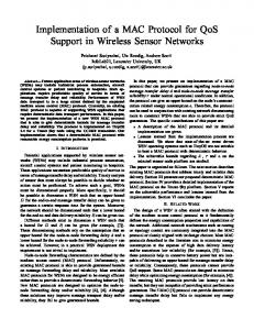
required at each input port would be the number of traffic classes multiplied by the number of output ports of the switch. On the other hand, it is necessary to employ some kind of regulation on the traffic to provide strict guarantees on throughput and latency. Toward this end, a connection admission control (CAC) can guarantee that at no link the load will be higher than the available bandwidth. Finally, providing QoS with the scheduling at switches is not enough, there must be some scheduling at the output of the network interfaces as well. Thereby, these devices also need to implement queues to separate the traffic classes. Therefore, we can conclude that to devote a VC per traffic class at the switches is not enough to provide adequate QoS and other techniques and mechanisms are necessary. More specifically, a CAC is needed to provide QoS support, network interfaces have to implement VCs, and at least VOQSW is needed to mitigate HOL blocking and buffer hogging. On the other hand, we have observed that once the traffic is regulated using a CAC, it flows seamlessly through the network. Congestion, if any, only happens temporarily. Therefore, regulated traffic flows with short latencies through the fabric. Given these conditions, to devote a different VC to each traffic class might be redundant. Most of the problems the additional VCs address are already solved by the rest of the mechanisms. For instance, bandwidth guarantees are achieved because the CAC assures that no link is oversubscribed and the VOQSW mitigates the HOL-blocking. Moreover, implementing a different VC per traffic class is not usually possible because final switch implementations do not incorporate so many VCs due to the associated cost in terms of silicon area. Finally, let us talk about buffer requirements. When using store and forward or virtual cut-through switching, the minimum buffer space that is needed to achieve maximum throughput is one packet size plus a roundtrip time (RTT) of data [22]. However, depending on the characteristics of traffic, like burstiness or locality, more memory at the buffers is necessary to obtain acceptable performance. As we have mentioned before, VCs produce a static partition of buffer memory. That means that traffic of one VC cannot use space devoted to another VC, even if it is available. For that reason, although VCs provide traffic isolation, they may degrade overall performance under bursty traffic. At Figure 1 we can see a little experiment to illustrate this. We inject 8 service levels of bursty traffic into a network. We evaluate two alternatives, one with eight
Average latency (µs)
4
8 VCs 2 VCs
40 30 20 10 0 8
16
32
64
128
Buffer space (Kbytes)
(a) Synthetic (self-similar)
50
8 VCs 2 VCs
40 30 20 10 0 8
16
32
64
128
Buffer space (Kbytes)
(b) Multimedia (MPEG-4)
Fig. 1. Average latency of QoS traffic with different buffer sizes per port (Input load = 100% link capacity; 64 end-nodes MIN; 16 port switches).
VCs (one per traffic class) and another with only two VCs. The total buffer space per port in both alternatives is the same, only the management changes1 . In the plot, we see the average latency of the four top-most priority service levels. We can see that the two VC design requires only 16 Kbytes of buffer per port to achieve the best performance, while the eight-VC alternative needs as much as 128 Kbytes per port to achieve the same performance. B. New proposal Our intention is to propose a switch architecture that uses only two VCs but still achieves traffic differentiation as if more VCs were used. Based on all the previous observations, we propose that all the regulated traffic that arrives at a switch port uses the same VC. In this way, we put most of the effort of the QoS provision on the network interfaces and in a proper CAC strategy, keeping the switches as simple as possible. Using the CAC, we achieve two goals: firstly, we can guarantee throughput. Secondly, as a consequence of the admission control, there is a bound on the latency of QoS packets. Note that the CAC and the complex network interfaces are needed anyway to provide strict QoS guarantees. We need a second VC at the switches for unregulated traffic, which should also be supported. That VC is used by the best-effort traffic, which can suffer from congestion. In order to avoid any influence on the regulated traffic, we give the latter absolute priority over best-effort traffic. Using just two VCs at the switches and provided that there is regulation in the traffic, we will obtain very similar performance as if we were employing many more VCs. At the end-points, there are schedulers that take into account the QoS requirements of traffic classes. 1
Packet size is tuned so there is always one packet size plus a RTT of buffer per VC. On the other hand, latency results are at message level, which in all the cases involves several packets.
5
Therefore, packets leaving the interfaces are ordered by the interface’s scheduler. If packet i leaves earlier than packet i + 1, it is because it was the best decision (with this scheduling strategy) to satisfy the QoS requirements of both packets, even if packet i + 1 was not at the interface when packet i left. Therefore, we can assume that the order in which packets leave the interfaces is correct. For the purposes of the switches, it is safe to assume that in all the cases packet i has more priority than packet i + 1. In this case, the switch is receiving at its input ports ordered flows of packets. Now, its task is analogous to the sorting algorithm: it inspects the first packet at each flow and chooses the one with the highest priority, building another ordered flow of packets. Note that what “priority” means will depend on the actual scheduling at the network interfaces. For instance, if absolute priority between traffic classes is applied, then the scheduler at the switches has to consider the original priority of the packets at the head of the queues, instead of just whether they are regulated traffic or not. If, for instance, the switch has four ports, the scheduler looks at the first packet of the four buffers and chooses the one with the highest priority. This is not very complex because very efficient priority encoder circuits have been proposed [23]. Note that this cannot lead to starvation on the regulated traffic because the CAC assures that there is enough bandwidth for all the regulated flows. Thereby, by using this scheduler, the switches achieve some reutilization of the scheduling decisions made at network interfaces. This is because the order of the incoming messages is respected, but at the same time, the switches merge the flows to produce a correct order at the output ports. Note that a different scheduler, like round-robin or iSLIP, would not merge the packets in the best way and the latency of the packets with the highest priority would be affected. A drawback of our technique is that the switches are not able to reschedule traffic as freely as they would be with a technique where a different VC for each traffic class were implemented. This problem is attenuated by the connection admission, because connections are only allowed if we can satisfy their bandwidth and latency requirements all along the path of packets. That means that the connections are established as if all the VCs were implemented at the switches and there were also the same schedulers as in the switches with all the VCs. In this way, we ensure that the required QoS load is feasible. We will not obtain exactly the same performance, but it will be very similar. On the other hand, the best-effort traffic classes only receive coarse-grain QoS, since they are not regulated.
However, the interfaces are still able to assign the available bandwidth to the highest priority best-effort traffic classes and, therefore, some differentiation is achieved among them. If stricter guarantees were needed by a particular best-effort flow, it should be classified as QoS traffic. Therefore, although best-effort traffic can obtain a better performance using more VCs, the results do not justify the higher expenses. Note that this proposal does not aim at achieving a higher performance but, instead, at drastically reducing buffer requirements while achieving similar performance and behavior of systems with many more VCs. In this way, a complete QoS support can be implemented at an affordable cost. Summing up, our proposal consists in reducing the number of VCs at each switch port needed to provide flows with QoS. Instead of having a VC per traffic class, we propose to use only two VCs at switches: one for QoS packets and another for best-effort packets. In order for this strategy to work, we guarantee that there is no link oversubscribed for QoS traffic by using a CAC strategy. IV. S WITCH
ARCHITECTURE
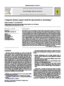
In this section, we describe thoroughly the proposed switch architecture. We study a 16 port, single-chip, virtual cut-through switch intended for clusters/SANs and for a 8 Gb/s line rate. We assume QoS support for distinguishing two traffic categories: QoS-requiring and best-effort traffic. Credit-based flow control is used to avoid buffer overflow at the neighbor switches and network interfaces. For the rest of the design constraints, like packet size, routing, etc. we take PCI AS [16] as a reference model. The block diagram in Figure 2 (a) shows the switch organization. We consider a combined input/output queued (CIOQ) switch because it offers line rate scalability and good performance [24]. Moreover, it can be efficiently implemented in a single chip. This is necessary in order to offer the low cut-through latencies demanded by current applications. Moreover, this also allows to provide some internal speed-up, without the need of faster external links. In the CIOQ architecture, output conflicts (several packets requesting the same output) are resolved by buffering the packets at the switch input ports. Packets are transferred to the switch outputs through a crossbar whose configuration is synchronously updated by a central scheduler. To cope with the inefficiencies of the scheduler and packet segmentation overheads2 , the 2 Crossbars inherently operate on fixed size cells and thus external packets are traditionally converted to such internal cells.
6
(a) Switch organization Fig. 2.
(b) Switch input port organization
Switch architecture.
crossbar core operates faster than the external lines (internal speed-up). Thus, output buffers are needed, resulting in the CIOQ architecture. In this architecture, the memory access rate needed (including input and output accesses) is (S + 1) × L, where L is the external line rate and S is the speed-up factor (1 means no speedup). By contrast, the required memory access rate is (N + 1) × L for output queuing architecture and (N + N ) × L for shared memory switches, where N is the number of switch ports. These access rates make these architectures less adequate for our design with the performance and technology we are aiming at. On the other hand, the buffered crossbar architecture has good performance and the memory access rate matches the line rate. However, with the technologies we are considering, it would be expensive to implement the required buffer space at the crosspoints. Detailed information on these alternative architectures can be found in [22], [25]. The organization that we propose for a switch input port can be seen in Figure 2 (b). There are only two VCs: VC 0 is intended for QoS traffic, while VC 1 is intended for best-effort traffic. Each VC is further dynamically divided into 16 queues, which correspond to each switch output port. These are logical queues which share the same physical memory and implement virtual output queuing (VOQ) at the switch level [26]. The output ports of the switch are simpler: there are only three queues, one per VC plus one for the outgoing credits. These queues, although sharing the same memory, are implemented in a static partition of the memory. Since this design is intended for a network with multiple switches, some head of line blocking [27] may appear on the VC 1 (best-effort traffic), although it would only affect the non-regulated traffic classes. Note that congestion in VC 0 (QoS-requiring traffic) is avoided by the CAC. In the evaluation section, we will use weighted round-
robin for the end-nodes. In this case, the best way to schedule our switches is the following. There is a strict precedence of VC 0 (QoS traffic) over VC 1 (best-effort traffic). Among the queues inside each VC, a simple FIFO algorithm is applied. The scheduling algorithm is very similar to iSLIP [28]. However, iSLIP was proposed as a cell-mode scheduler: external packets are split into fixed size internal cells which are scheduled ignoring which cell belongs to which packet. In that case, packet reassembly is required at the switch output, and cutthrough cannot be used. Since we want to provide virtual cut-through switching, our scheduling decisions are made for whole packets (packet-mode scheduling [29]). In this way, once a packet is selected by the scheduler, the crossbar connection is kept until all cells of the packet have been delivered to the output. This allows the output port to start transmitting the packet on the line as soon as the first cell of the packet arrives at the switch output. V. D ESIGN
EVALUATION
In the following, we study the silicon area, the power consumption, and the expected cut-through latency of the switch architecture proposed in the previous section. We consider 0.18 µm and 0.13 µm technologies, because they are popular in interconnection components and plenty of information is available. A. Silicon area In order to find out the area requirements of this design, we consider the individual components of the switch core. These are the buffers, the crossbar and the scheduler. Table I shows area estimates for each module. The internal clock of the system is 250 MHz and the datapath is 64 bits wide. This provides a crossbar speed of 16 Gbit/s, which is twice the speed of the external links. That means there is an internal speed-up of 2.0.
7
TABLE I A REA CONSUMPTION BY COMPONENTS .
Module Buffers (32 × 16KB ) Crossbar and datapath Scheduler Total
T. 0.18 µm T. 0.13 µm 64 mm2 32 mm2 2 10 mm 5 mm2 5 mm2 3 mm2 79 mm2 40 mm2
The number of buffers at the switch comes from 16 ports per input and output. We chose 16 Kbytes per port (which are shared between the two VCs, 8 Kbytes each) as a compromise between silicon area and performance. The memory area estimates are based on datasheets of typical ASIC technologies available to European Universities. The crossbar and datapath estimates come from the actual numbers of the switch design in [3]. Finally, we base our estimates for the scheduler area on the data provided by McKeown in [28]. Note that usually there is not a full utilization of the available area in an ASIC design [30] and, therefore, the final chip would be larger. In order to find out more accurate estimates, all the design flow should be performed. However, these area estimates are very helpful to compare the alternative architectures. B. Power consumption In order to figure out the power consumed by this design, we follow a similar methodology to that of the previous section: we will analyze the power consumption of each individual component. Note that power consumption heavily depends on the activity of the different components and, therefore, on the load of the system. In the following, we consider worst-case power consumption. TABLE II P EAK POWER CONSUMPTION BY COMPONENTS .
Module T. 0.18 µm T. 0.13 µm Transceivers 9.0 Watt 6.4 Watt Buffers 4.0 Watt 2.6 Watt Crossbar and datapath 3.0 Watt 1.8 Watt Scheduler 0.9 Watt 0.5 Watt Total 16.9 Watt 11.3 Watt In Table II, we see the estimates for the different elements (since these are estimates, we round the results to one decimal). Serializer-Deserializer circuits (also known as transceivers) are the most power consuming part of the switch [2]. According to [31], the transceivers
consume 175 mW per 2.5 Gb/s of full duplex bandwidth, in 0.18 µm technology. The figure drops to 125 mW in 0.13 µm technology. As our switch design provides an aggregate throughput of 128 Gb/s, we obtain the results shown at Table II. We also consider power consumed by the memory at the ports. The worst case would happen when all the memory ports are accessed simultaneously. The buffers that we assume (250 MHz, 64 bits wide, two access ports) typically consume 0.5 mW per MHz in 0.18 µm and 0.32 mW per MHz in 0.13 µm. For the crossbar and datapath, and for the scheduler, we obtain our numbers from the theoretical study in [32], using the appropriate parameters for the equations in [33]. Moreover, we have compared these figures with those in [3], confirming that the results are quite reasonable. C. Cut-through latency Finally, we calculate the expected delay of the header of a packet crossing our switch. We assume a pipelined design of the switch, as is usually the case in current high performance switches. The stages of our design to process a message are: • Header decoding/Routing/VC allocation. Routing is very quick since we use source routing (as in PCI AS). We can assume that this is partially performed in conjunction with the next stage. • Block allocation. Since we are using dynamic queues, blocks at the memory of the input ports must be allocated for the incoming data. This allocation involves the management of linked lists of these blocks. For a detailed description of these algorithms, consult [22], [25]. • Writing and scheduling. Scheduling of a block can take place in parallel with its storage at the input buffer. • Crossbar traversal. This operation consists in transferring the blocks through the crossbar to the output buffers. • Output scheduling. Since there are two queues at output ports, some scheduling is needed. VC 0 and VC 1 statically share the memory space at the outputs to avoid buffer hogging. In addition to these VCs, there is a third queue for the outgoing credits, since we assume that there are no special lines for flow control. We can see in Figure 3 the stages of processing a message. The first and the last operations are performed very quickly, while the operations in the shaded box have to process whole blocks of 64 bytes. These three
8
Fig. 3.
Packet processing at the switch.
block-size operations form the pipeline stages. Taking this into account, our switch model differs from other canonical models [34], [35] in the output buffering and the corresponding scheduling. The latency of the first operation would be 1 cycle, which translates to 4 ns. The time to process a block of 64 bytes with a clock cycle of 4 ns and with a datapath of 64 bits would be 32 ns. The latency of the three stages operating over these blocks is 3×32 ns = 96 ns. Finally, the output scheduling could also be performed in a single cycle, since very efficient priority encoder circuits have been proposed [23]. Therefore, the total latency would be 4+96+4 = 104 ns. In addition to this, the latency of the transceiver should be added. This would depend on the specific circuit used, but in [36] there is a very detailed timing analysis of one that would take around 40 ns; a complete implementation process would be necessary for more accurate delays. Finally, we have confirmed these results using the theoretical analysis in [35], which is itself based on the theory of logical effort [37]. This theory provides a simple and broadly applicable method for estimating the delay of high-speed integrated circuits. The results we obtain in this way are in the same order of magnitude of the 104 ns value.
D. Final remarks In conclusion, our design is feasible with the current technology. Note that if we were to implement a full number of VCs, like it is proposed in the specifications of PCI AS or InfiniBand, then much more buffer space per port would be needed: each VC should have an amount of memory proportional to the round trip time (RTT). With the trend of increasing RTT and line rate [2], this amount would be large and, therefore, the number of ports of the switch would have to be reduced to keep within reasonable limits of area, power, and latency. Note that, as technology improves, this problem persists: less ports can be implemented in the chip if a lot of VCs/buffer are needed at each port.
After this hardware characteristics study, we procede to examine, through simulation, the performance of this switch architecture in the following section. VI. S IMULATION
CONDITIONS
In this section, we will explain the simulated network architecture. We will also give details on the parameters of the network and the load used for the evaluation.
A. Simulated architecture We have performed the tests considering four cases. First, we have tested the performance of our proposal, which uses 2 VCs at each switch port (the network interfaces still use 8 VCs). There are two variants of this proposal, depending on the number of ports of the switches. We have evaluated 32 Kbytes/port and 16 ports/switch, and 64 Kbytes/port and 8 ports/switch. In both cases, the total buffer memory in the switch is the same. These cases are noted New 2 VCs-P (more ports) and New 2 VCs-B (larger buffers). We have also performed tests with switches using 8 VCs (as many VCs as traffic classes). In this case, it is referred to in the figures as Traditional 8 VCs. However, we have also included the same two variants as with our proposal. Therefore, we have Traditional 8 VC-P (32 Kbytes/port and 16 ports/switch) and Traditional 8 VC-B (64 Kbytes/port and 8 ports/switch). These switches have the same memory per port as their 2 VC counterparts. Therefore, the four switch models would use the same total memory and roughly the same silicon area. Note that, actually, Traditional 8 VC cases are more complex and would take higher delays, but this is not taken into account in our performance evaluation for the sake of clarity. In this paper we have not shown results of traditional 2 VC architectures, with only 2 VCs at the end-nodes and the switches. There are results in [4] that show that these architectures behave very poorly if more that 2 traffic classes are used.
9
The network used to test the proposals is a butterfly multi-stage interconnection network (MIN) with 64 endpoints. The actual topology is a folded (bidirectional) perfect-shuffle. We have chosen a MIN because it is a usual topology for clusters. However, our proposals are valid for any network topology, including both direct networks and MINs. The network interfaces have the same structure as the output ports of their switch counterparts, with some variations: they implement the full number of VCs in all the cases (including the New 2 VC cases), there is a queue per end-point and VC combination, and the length of those host-interface queues is infinite, to simulate the large buffers at these devices. Our proposal is based on reusing the scheduling performed at network interfaces. We have to configure them properly to achieve the desired results. Depending on the scheduler used at the interfaces, the results will vary. In [4] we used absolute priorities among 8 traffic classes. We also guaranteed throughput by using a CAC. In this paper we show a different set of results, based on weighted round-robin scheduling [38] similar to the proposals of InfiniBand and PCI AS. However, note that our proposal of simplifying the switch ports, reusing the decisions taken in the network interfaces, is independent of the specific scheduling algorithm used at the output of these interfaces. How to configure this scheduler is out of the scope of this paper. We followed the methodology at [15]. In this way, we can provide similar throughput and latency guarantees to that of the aforementioned standards. The CAC we have implemented for QoS-requiring traffic is a simple one, based on average bandwidth. Each connection is assigned a path where enough bandwidth is assured. The CAC guarantees that less than 70% of bandwidth is used by QoS traffic at any link. The other 30% of available bandwidth will be used by non-regulated traffic. We also use a load-balancing mechanism when a QoS connection is stablished, which consists in assigning the least occupied route among the possible paths. To build the 64-port MIN, we need 48 switches and 192 links with the 8 port architectures. The final cost of the interconnect greatly depends on the number of switches used, while the power consumption comes mostly from the transceivers needed to drive the links, and thus, depends on the actual number of links [39]. On the other hand, the 16 port designs would implement more ports in the chip by reducing the amount of buffer space per port. Note that using these switch models, it takes just 16 switches (67% less than the Traditional 8 VC-B case) and 128 links (33% less than the Traditional 8 VC-B case) to build the 64 ports MIN.
This greatly reduces the cost and power-consumption of the network.
B. Traffic model Table III presents the characteristics of the traffic injected in the network. We have considered the traffic classes (TCs) defined by the IEEE standard 802.1D2004 [19] at the Annex G, which are generally accepted for interconnection networks. However, we have added an eighth TC, Preferential Best-effort, with a priority between Excellent-effort and Best-effort. In this way, the workload is composed of 8 different TCs: four QoS TCs and four best-effort TCs. TABLE III T RAFFIC INJECTED PER HOST.
Name Network Control Audio Video Controlled Load Excellent-effort Pref. Best-effort Best-effort Background
% BW 1.0 16.33 16.33 16.33 12.5 12.5 12.5 12.5
Notes self-similar CBR 64 KB/s conns. 750 KB/s MPEG-4 CBR 1 MB/s conns. self-similar self-similar self-similar self-similar
The proportion of each category has been chosen to provide meaningful results. Our intention is to lead the network to a situation where the different TCs have to compete for limited resources. We also want to have diversity between the sources, combining different packet sizes and different traffic distributions, that is, constant bit rate (CBR) flows combined with variable bit rate (VBR) flows. It is possible that this mix of traffic is not actually present in a real-life cluster, but it serves perfectly to show the advantages of the different architectures we are testing. Real-life packet destinations are not uniformly distributed; rather, traffic tends to be focused on preferred or popular destinations. This being so, a flexible destination distribution model based on Zipf’s law has been proposed [40]. Therefore, the destination pattern we have used is based on Zipf’s law [41], as recommended in [42]. Zipf’s law states the frequency of occurrence of certain events, as a function of the rank. In this way, the probability that an arriving packet is heading toward a destination with rank i is given by Equation 1, where i is the rank of packet destination, k is the Zipf order and N is the number of addresses.
10
6 4 2 0 0.2
0.4
0.6
0.8
1
Normalized load
10
6 4 2 0 0
0.2
0.4
0.6
0.8
1
Normalized load 1
30 20 10 0 0
50
0.6
0.8
1
Trad. 8VC−P Trad. 8VC−B New 2VC−P New 2VC−B
40 30 20 10 0 0
1
0.4
0.6
0.8
Trad. 8VC−P Trad. 8VC−B New 2VC−P New 2VC−B
0.4 0.2
0
0
Results for Audio traffic.
0.4
0.6
0.2
Latency (µs)
0.2
Normalized load 0.8
0.6
Fig. 5.
0.4
Normalized load
Trad. 8VC−P Trad. 8VC−B New 2VC−P New 2VC−B
0.8
0.2
Results for Network Control traffic.
Trad. 8VC−P Trad. 8VC−B New 2VC−P New 2VC−B
8
Trad. 8VC−P Trad. 8VC−B New 2VC−P New 2VC−B
40
10
Fig. 4.
50
1
0
Maximum latency (µs)
Trad. 8VC−P Trad. 8VC−B New 2VC−P New 2VC−B
8
0.1
In this section, the performance of our proposals is shown. We have considered three traditional QoS indices for this performance evaluation: throughput, latency, and jitter. Note that packet loss is not considered because no packets are dropped due to the use of credit-based flow control. Maximum jitter determines the receiver’s user space for audio and video. Inappropriate results of latency or jitter may lead to dropped packets at the application level. For that reason, we also show the cumulative distribution function (CDF) of latency and jitter, which represents the probability of a packet achieving a latency or jitter equal to or lower than a certain value.
10
Maximum latency (µs)
RESULTS
In this scenario, there is the same proportion of QoS traffic as best-effort traffic. We first study the results of QoS traffic. In Figure 4, we show the performance of Network Control traffic. This TC demands very little bandwidth but a latency as short as possible. In this case, average results are very similar using our proposal, compared with their traditional counterparts. That is, the New 2VC-B case behaves like the Traditional 8VC-B case, and the same happens with the New 2VC-P and Traditional 8VC-P cases. On the other hand, maximum latency is increased, for Network Control, approximately 50%. Note that maximum latencies are still aceptable in all the cases.
CDF
VII. S IMULATION
A. Initial scenario
10
In this way, the traffic is not uniformly distributed, but, instead, for each TC and input port a ranking is established among all the possible destinations. Therefore, there will be destinations with a higher chance of being elected by a group of flows, where this probability is obtained with the aforementioned Zipf’s law. The global effect is a potential full utilization of the network, but with a reduced performance compared with a uniform distribution. If the Zipf order k is fixed to 0, then the destination distribution would be uniform. On the other hand, experimental research [40] has found that the value of k = 1 is the closest to real traffic. In our tests, the packets are generated according to different distributions, as can be seen in Table III. Audio, Video, and Controlled Load traffic are composed of point-to-point connections of the given bandwidth. Note that Audio traffic models both the audio part of the video transmissions and plain audio connections. The self-similar traffic is composed of bursts of packets heading to the same destination. In that case, the packets’ sizes are governed by a Pareto distribution, as recommended in [43]. In this way, many small size packets are generated, with an occasional large size packet. The periods between bursts are modelled with a Poisson distribution. With this distribution, if the burst size is long (60 packets, approximately 10 Kbytes), there is a lot of temporal and spatial locality and should show worst-case behavior because at a given moment, many packets are grouped going to the same destination. The length of the bursts will be noted as the B parameter in the figures.
1
j=1
0.1
j −k
Average latency (µs)
(1)
Average latency (µs)
N X
In the following, we will see several experiments. Firstly, we evaluate an initial scenario where the input QoS load is equal to the best-effort load. Afterwards, we will study which amount of QoS traffic can be allowed at each architecture before its performance is unacceptable. We consider QoS performance to be unacceptable when the bandwidth and maximum latency requirements are not achieved. Finally, we vary the size of the network, from 64 to 512 end-nodes, to study the scalability of our proposal.
CDF
Zipf (i) =
i−k
Jitter (µs)
1
100
Trad. 8VC−P Trad. 8VC−B New 2VC−P New 2VC−B
80 60 40 20 0
0.2
0.4
0.6
0.8
1
Normalized load 1
CDF
0.4
0 100
0 10
0.6
0.8
1
Trad. 8VC−P Trad. 8VC−B New 2VC−P New 2VC−B
Trad. 8VC−P Trad. 8VC−B New 2VC−P New 2VC−B
CDF
4
0.6 0.4 0.2
2
0.2
0.4
0.6
0.8
1
Normalized load
Fig. 7.
10
0
1
0
0
0.1
Average latency (µs)
1 0.8
60 40 20
1
0
0.2
0.4
0.6
0.8
1
Normalized load (b) Pref. Best-effort
Trad. 8VC−P Trad. 8VC−B New 2VC−P New 2VC−B
80 60 40 20
100
Trad. 8VC−P Trad. 8VC−B New 2VC−P New 2VC−B
80 60 40 20 0
Fig. 8.
Results for Video traffic.
6
0.8
0.2
0.4
0.6
0.8
1
Normalized load (c) Best-effort
Jitter (µs)
Trad. 8VC−P Trad. 8VC−B New 2VC−P New 2VC−B
8
100
0
The Video traffic is very bursty, since it involves the transmission of large video frames (around 40 Kbytes). This characteristic increases the latency and jitter results compared with the Audio traffic performance for all the architectures studied as can be seen in Figure 6. However, note that even in this case, our proposal offers results very similar to those of the Traditional 8 VCs architectures. 10
0.6
0
0.4 0.2
Fig. 6.
0.4
0.6
0.2
Latency (µs)
0.2
Normalized load 0.8
0.6
1
CDF
0
1
Trad. 8VC−P Trad. 8VC−B New 2VC−P New 2VC−B
0.8
20
0
0.4
Throughput (%)
0
Throughput (%)
0
40
Trad. 8VC−P Trad. 8VC−B New 2VC−P New 2VC−B
80
0
0.2
0.4
0.6
0.8
1
Normalized load (d) Background
Performance of best-effort traffic classes.
100
5
60
10
10
0.2
Normalized load (a) Excellent-effort
Trad. 8VC−P Trad. 8VC−B New 2VC−P New 2VC−B
80
1
Maximum latency (µs)
15
100
0.1
Average latency (µs)
Trad. 8VC−P Trad. 8VC−B New 2VC−P New 2VC−B
100
0 0
20
Throughput (%)
Figure 5 shows the performance of Audio traffic for the four cases of study. The latency results are almost the same when using our New 2VC proposals, compared with the Traditional 8VC cases. This is true for both average and maximum latency, and for jitter as well.
Throughput (%)
11
Latency (µs)
Results for Controlled Load traffic.
The three architectures we are studying also offer 100% throughput to the Controlled Load traffic (Figure 7) due to the CAC. Although this is the unique requirement of this TC, note that also in this case our proposals behave very similar to ther coounterparts with 8 VCs. Regarding the best-effort TCs, results are almost the same in the four cases. However, we can see at Figure 8 that maximum throughput is achieved with the New 2VC-B architecture while the worst results correspond to the Traditional 8VC-P case. This is because buffer memory can be used more efficiently when it is only splitted in 2 VCs instead of 8 VCs.
We can conclude at this point that the four studied architectures offer similar performance: 8 VC architectures have some advantage on the latency of Network Control traffic due to their better traffic isolation, whereas 2 VC architectures reduce the number of VCs required and increase global throughput due to the improved buffer management. B. QoS traffic acceptance In this section we evaluate which amount of QoS traffic can be accepted by each architecture before QoS requirements are not satisfied. In this section we do not use the limitation of 70% maximum load of the links when establishing connections. In this scenario we vary the proportion of QoS traffic, from 10% to 90% of the total available network load. We fill in the remaining bandwidth with best effort-traffic. Therefore, input links are injecting at 100% of their capacity. We can see that the different TCs saturate at different points when using the four architectures. In this way, QoS requirements are satisfied only up to a certain level of QoS traffic load. We consider that acceptable maximum latency for Network Control and Audio is 500 µs, while for Video is 1000 µs, as recmmended in [1]. We can observe in Figure 9 the maximum latency results. On the other hand, we find throughput results in Figure 10. We can see at Table IV which is the maximum QoS load at which the different architectures yield acceptable results. For instance, performance of Audio traffic with the architecture Traditional 8VC-P is only acceptable up to a QoS load of 70%. If more QoS traffic were injected, it would cause the maximum latency bound to be traspassed.
100
Trad. 8VC−P Trad. 8VC−B New 2VC−P New 2VC−B
80 60 40 20 0 0
20
40
60
80
100
Maximum latency (µs)
Average latency (µs)
12
500
TABLE IV
Trad. 8VC−P Trad. 8VC−B New 2VC−P New 2VC−B
400
M AXIMUM Q O S
300
100 0 0
20
% of QoS traffic
40
60
80
100
% of QoS traffic
60 40 20 0 0
20
40
60
80
100
Maximum latency (µs)
Average latency (µs)
Trad. 8VC−P Trad. 8VC−B New 2VC−P New 2VC−B
80
500
Trad. 8VC−P Trad. 8VC−B New 2VC−P New 2VC−B
400
200 100 0 0
20
40
60
80
100
% of QoS traffic
Trad. 8VC−P Trad. 8VC−B New 2VC−P New 2VC−B
60 40 20 0 0
20
40
60
80
100
Maximum latency (µs)
Average latency (µs)
(b) Audio 80
Network Control Audio Video Controlled Load All QoS
Trad. 8VC-B 90% 80% 90% 70% 70%
New 2VC-P 80% 80% 90% 80% 80%
New 2VC-B 90% 80% 90% 90% 80%
300
% of QoS traffic
100
Trad. 8VC-P 90% 80% 80% 60% 60%
Traffic Class
200
(a) Network Control 100
LOAD WITH ACCEPTABLE PERFORMANCE .
1000
Trad. 8VC−P Trad. 8VC−B New 2VC−P New 2VC−B
800 600 400 200 0 0
% of QoS traffic
20
40
60
80
100
% of QoS traffic
the QoS requirements can be satisfied. We can see that both architectures using our proposal can accept up to 80% of QoS traffic, whereas the Traditional 8VC-P and Traditional 8VC-B cases can only accept 70% and 60%, respectively. This is because of the buffer management efficency issue we have discussed before. Taking into account these results, our proposal is able to cope with more QoS traffic while keeping QoS guarantees. This is due to a more flexible buffer management. We also conclude that the New 2VC-P architecture is better than the New 2VC-B because performance is similar but the first greatly reduces component count.
100
Trad. 8VC−P Trad. 8VC−B New 2VC−P New 2VC−B
80 60 40 20 0 0
20
40
60
80
% of QoS traffic
100
Maximum latency (µs)
Average latency (µs)
(c) Video 1000
Trad. 8VC−P Trad. 8VC−B New 2VC−P New 2VC−B
800
C. Scalability and power consumption
600 400 200 0 0
20
40
60
80
100
% of QoS traffic
To finish with the experiments, we perform a scalability study. We observe the results of varying network size from 64 to 512 end-nodes. In addition to the performance of the network, we analyze the power consumption at each configuration.
Performance of QoS traffic varying QoS load.
100
100 80 60 40 20 0
Trad. 8VC−P Trad. 8VC−B New 2VC−P New 2VC−B 128
256
512
End nodes (a) Global throughput
80 60
Average latency (µs)
Throughput (%)
64
40 Trad. 8VC−P Trad. 8VC−B New 2VC−P New 2VC−B
20 0 0
Fig. 10.
Average latency (µs)
Fig. 9.
Throughput (%)
(d) Controlled Load
20
40 60 % of QoS traffic
80
100
Aggregated throughput of QoS traffic varying QoS load.
The last row of the table contains the minimum of the column, which means the maximum QoS load where all
50 40
14 12 10
Trad. 8VC−P Trad. 8VC−B New 2VC−P New 2VC−B
8 6 4 2 0 64
128
256
512
End nodes (b) Average latency of Network Control traffic
Trad. 8VC−P Trad. 8VC−B New 2VC−P New 2VC−B
30 20 10 0 64
128
256
512
End nodes (c) Maximum latency of Network Control traffic
Fig. 11.
Scalability of our proposal.
In Figure 11, we show the scalability of the four cases studied attending to different parameters. Global
13
throughput is very similar in the four cases, although our New 2VC-B architecture offers better results due to buffer design. Regarding latency of Network Control traffic, the most delay-sensitive TC of all studied, it scales well both in terms of average and maximum latency for the four architectures.
Variation (in %)
100
Switches reduction Links reduction Power con. reduction
80 60 40 20 0 64
128 256 End nodes
512
Fig. 12. Advantages of New 2VC-P proposal, compared with Traditional 8VC-B case.
Figure 12 summarizes the trade-offs of using our New 2VC-P proposal against Traditional 8VC-B case. As can be seen, there is a very noticeable reduction in chip3 and link counts and, therefore, in the associated power consumption of the interconnection network. This is due to the extra ports in New 2VC-P switches. Note that Traditional 8VC-P switches, offer much worse performance than New 2VC-P switches, as we have seen in the previous section. According to these results, we can conclude that our proposal can provide an adequate QoS performance. Using our switches, we greatly decrease the cost and power-consumption of the interconnection with excellent performance.
opens up the possibility of using the remaining VCs for other concerns, like adaptive routing or fault tolerance. Furthermore, it is also possible to reduce the number of VCs supported at the switches, thereby simplifying the design, or increasing the number of ports. We have proposed a switch design which benefits from that proposal. We have examined its feasibility as a single-chip switch and the hardware constraints that would have. We also have compared, through simulation, the performance of this design with that of more traditional architectures. The proposed design outperforms the traditional design in overall throughput, due to better buffer utilization, while lagging behind in some latency results, because an 8 VC switch can do a better job in preserving packet ordering than a 2 VC switch. We believe this is an advantageous trade-off, as we have seen in the performance evaluation. Finally, in this paper we have also shown that our proposal is able to scale properly. The results with large network sizes are almost as good as with smaller networks and the difference keeps constant. We have also examined the power consumption for different interconnects, ranging from 64 to 512 end nodes. For all of them, we cut half of the power consumed by the interconnect. We are currently examining a number of possible extensions to the work here presented. We are preparing a study on more complex switch models that can benefit from our proposal, such as switches using EDF arbitration. We also intend to use this technique in other environments, like Internet routers or networks on chip. IX. ACKNOWLEDGMENTS The authors would like to thank Manolis Katevenis and Georgios Passas, from ICS-FORTH (Heraklion, Crete, Greece), for their contribution to the development of the ideas presented. R EFERENCES
VIII. C ONCLUSIONS In [4], we presented briefly our proposal that consists in making the network elements cooperate, building together ordered flows of packets. Consequently, the switches try to respect the order in which packets arrive at the switch ports, which is probably correct. This allows a drastic reduction in the number of VCs required for QoS purposes at each switch port. This study has shown that it is possible to achieve a more than acceptable QoS performance with only two VCs. We reuse at the switches the scheduling decisions made at the network interfaces. This VC reduction 3 Remember that both New 2VC-P and Traditional 8VC-B switches take equivalent silicon area.
[1] D. Miras, “A survey on network QoS needs of advanced internet applications,” Internet2 - QoS Working Group, Tech. Rep., 2002. [2] C. Minkenberg, F. Abel, M. Gusat, R. P. Luijten, and W. Denzel, “Current issues in packet switch design,” in ACM SIGCOMM Computer Comm. Review, vol. 33, Jan. 2003, pp. 119–124. [3] D. Simos, “Design of a 32x32 variable-packet-size buffered crossbar switch chip,” Inst. of Computer Science, FORTH, Tech. Rep. FORTH-ICS/TR-339, July 2004. [4] A. Mart´ınez, F. J. Alfaro, J. L. S´anchez, and J. Duato, “Providing full QoS support in clusters using only two VCs at the switches,” in Proceedings of the 12th International Conference on High Performance Computing (HiPC), Dec. 2005, pp. 158–169, available at http://investigacion.uclm.es/portali/ documentos/it 1131561750-HiPC05.pdf. [5] P. Ferguson and G. Huston, Quality of service: delivering QoS on the Internet and in corporate networks. John Wiley & Sons, Inc., 1998.
14
[6] X. Xiao and L. Ni, “Internet QoS: A Big Picture,” IEEE Network Magazine, pp. 8–18, Mar. 1999. [7] D. Chalmers and M. Sloman, “A survey of quality of service in mobile computing environments,” IEEE Communications Surveys and Tutorials, vol. 2, no. 2, 1999. [Online]. Available: citeseer.ist.psu.edu/chalmers99survey.html [8] D. Bull, N. Conagarajah, and A. Nix, Insights into Mobile Multimedia Communications. Academic Press, 1999. [9] J. Duato, S. Yalamanchili, M. B. Caminero, D. Love, and F. Quiles, “MMR: A high-performance multimedia router. Architecture and design trade-offs,” in Proceedings of the 11th Symposium on High Performance Computer Architecture (HPCA), Jan. 1999. [10] K. H. Yum, E. J. Kim, C. R. Das, and A. S. Vaidya, “MediaWorm: A QoS capable router architecture for clusters,” IEEE Transactions on Parallel Distributed Systems, vol. 13, no. 12, pp. 1261–1274, Dec. 2002. [11] L. Zhang, “VirtualClock: A new traffic control algorithm for packet switched networks,” ACM Transaction on Computer Systems, vol. 9, 2, pp. 101–124, 1991. [12] J. Duato, A. Robles, F. Silla, and R. Beivide, “A comparison of router architectures for virtual cut-through and wormhole switching in a NOW environment,” J. Parallel Distrib. Comput., vol. 61, no. 2, pp. 224–253, 2001. [13] K. Yum, E. Kim, and C. Das, “QoS provisioning in clusters: An investigation of router and NIC design,” in Proceedings of the 28th Annual International Symposium on Computer Architecture (ISCA). IEEE Computer Society, July 2001. [14] InfiniBand architecture specification volume 1. Release 1.0, InfiniBand Trade Association, Oct. 2000. [15] F. J. Alfaro, J. L. S´anchez, and J. Duato, “QoS in InfiniBand subnetworks,” IEEE Transactions on Parallel Distributed Systems, vol. 15, no. 9, pp. 810–823, Sept. 2004. [16] ASI SIG, Advanced switching core architecture specification, 2005. [17] A. Hung, G. Kesidis, and N. Mckeown, “ATM input-buffered switches with guaranteed-rate property,” in Proceedings of IEEE Symposium on Computers and Communications, 1998. [18] W. Dally, P. Carvey, and L. Dennison, “Architecture of the Avici terabit switch/router,” in Proceedings of the 6th Symposium on Hot Interconnects, 1998, pp. 41–50. [19] IEEE, “802.1D-2004: Standard for local and metropolitan area networks,” 2004, http://grouper.ieee.org/groups/802/1/. [20] N. Chrysos and M. Katevenis, “Multiple priorities in a two-lane buffered crossbar,” in Proceedings of the IEEE Globecom 2004 Conference, Nov. 2004, cR-ROM paper ID “GE15-3”. [21] D. C. Stephens and H. Zhang, “Implementing distributed packet fair queueing in a scalable switch architecture,” in INFOCOM (1), 1998, pp. 282–290. [22] J. Duato, S. Yalamanchili, and N. Lionel, Interconnection networks. An engineering approach. Morgan Kaufmann Publishers Inc., 2002. [23] C. Huang, J. Wang, and Y. Huang, “Design of high-performance CMOS priority encoders and incrementer/decrementers using multilevel lookahead and multilevel folding techniques,” IEEE Journal of Solid-State Circuits, vol. 1, no. 37, pp. 63–76, Jan. 2002. [24] S.-T. Chuang, A. Goel, N. McKeown, and B. Prabhakar, “Matching output queueing with a combined input output queued switch,” in INFOCOM (3), 1999, pp. 1169–1178. [25] W. J. Dally and B. Towles, Principles and Practices of Interconnection Networks. Morgan Kaufmann Publishers Inc., 2003. [26] T. Anderson, S. Owicki, J. Saxe, and C. Thacker, “High-speed switch scheduling for local-area networks,” ACM Transactions on Computer Systems, vol. 11, no. 4, pp. 319–352, November 1993.
[27] M. J. Karol, M. G. Hluchyj, and S. P. Morgan, “Input versus output queueing on a space-division packet switch,” IEEE Trans. on Commun., vol. COM-35, pp. 1347–1356, 1987. [28] N. W. McKeown, “The iSLIP scheduling algorithm for inputqueued switches,” IEEE/ACM Transactions on Networking, vol. 7, pp. 188–201, 1999. [29] M. A. Marsan, A. Bianco, P. Giaccone, E. Leonardi, and F. Neri, “Packet-mode scheduling in input-queued cell-based switches,” IEEE/ACM Trans. Netw., vol. 10, no. 5, pp. 666–678, 2002. [30] N. H. E. Weste and D. Harris, CMOS VLSI Design: A Circuits and Systems Perspective. Addison-Wesley, 2005. [31] A. Younis, C. Boecker, K. Hossain, F. Abughazaleh, B. Das, Y. Chen, M. Robinson, S. Irwin, and B. Grung, “A low jitter, low power, cmos 1.25-3.125gbps transceiver,” in Proceedings of the 27th European Solid-State Circuits Conference (ESSCIRC 2001), 2001. [32] H.-S. Wang, L.-S. Peh, and S. Malik, “A power model for routers: Modeling Alpha 21364 and InfiniBand routers,” in HOTI ’02: Proceedings of the 10th Symposium on High Performance Interconnects HOT Interconnects (HotI’02). Washington, DC, USA: IEEE Computer Society, 2002, p. 21. [33] H.-S. Wang, “A detailed architectural-level power model for router buffers, crossbars and arbiters,” Department of Electrical Engineering, Princeton University, Tech. Rep., 2004. [34] J. Duato and P. L´opez, “Performance evaluation of adaptive routing algorithms for k-ary-n-cubes,” in PCRCW ’94: Proceedings of the First International Workshop on Parallel Computer Routing and Communication. London, UK: Springer-Verlag, 1994, pp. 45–59. [35] L. Peh and W. Dally, “A delay model and speculative architecture for pipelined routers,” in Proceedings of the 7th International Symposium on High-Performance Computer Architecture. IEEE Computer Society, 2001, p. 255. [36] “Virtex-4 RocketIO multi-gigabit transceiver,” Xilinx, Inc., User Guide UG076 (v2.0), 2006. [37] I. Sutherland, B. Sproull, and D. Harris, Logical effort: designing fast CMOS circuits. San Francisco, CA, USA: Morgan Kaufmann Publishers Inc., 1999. [38] M. Katevenis, S. Sidiropoulos, and C. Courcoubetis, “Weighted round-robin cell multiplexing in a general-purpose ATM switch,” IEEE J. Select. Areas Commun., pp. 1265–1279, Oct. 1991. [39] L. Shang, L. S. Peh, and N. K. Jha, “Dynamic voltage scaling with links for power optimization of interconnection networks,” in Proceedings of the 9th Symposium on High Performance Computer Architecture (HPCA), February 2003, pp. 91–102. [40] L. Breslau, P. Cao, L. Fan, G. Phillips, and S. Shenker, “Web caching and zipf-like distributions: Evidence and implications,” in INFOCOM (1), 1999, pp. 126–134. [41] G. K. Zipf, The Psycho-biology of Languages. HoughtonMiffin, MIT, 1965. [42] I. Elhanany, D. Chiou, V. Tabatabaee, R. Noro, and A. Poursepanj, “The network processing forum switch fabric benchmark specifications: An overview,” IEEE Network, pp. 5–9, Mar. 2005. [43] R. Jain, The art of computer system performance analysis: techniques for experimental design, measurement, simulation and modeling. John Wiley and Sons, Inc., 1991.
15
Alejandro Mart´ınez Alejandro Mart´ınez received the MS degree in computer science from the University of Castilla-La Mancha in 2003 and is currently working toward the PhD degree. He is currently a research assistant in the Computer Systems Department at the Castilla-La Mancha University. His research interests include high-performance interconnections, quality of service, design of highperformance switches, and high-performance computing.
Francisco J. Alfaro Francisco J. Alfaro received the MS degree in computer science from the University of Murcia in 1995 and the PhD degree from the University of Castilla-La Mancha in 2003. He is currently an assistant professor of computer architecture and technology in the Computer Systems Department at the Castilla-La Mancha University. His research interests include high-performance local area networks, quality of service, design of high-performance routers, and design of on-chip interconnection networks for multicore systems.
Jos´e L. S´anchez Jos´e L. S´anchez received the PhD degree from the Technical University of Valencia, Spain, in 1998. Since November 1986 he is a member of the Computer Systems Department (formerly Computer Science Department) at the University of Castilla-La Mancha. He is currently an associate professor of computer architecture and technology. His research interests include multicomputer systems, quality of service in high-speed networks, interconnection networks, parallel algorithms, and simulation.
Francisco J. Quiles Francisco J. Quiles received the degree in Physics (Electronics and Computer Science) and the PhD degree from the University of Valencia, Spain, in 1986 and 1993, respectively. In 1986 he joined the Computer Systems Department at University of Castilla-La Mancha, where he is currently a Full Professor of Computer Architecture and Technology and Vice-rector of Research of the University of Castilla-La Mancha. He has developed several courses on computer organization and computer architecture. His research interests include high-performance networks, parallel algorithms for video compression, and video transmission. He has published over 120 papers in international journals and conferences.
Jos´e Duato Jos´e Duato is Professor in the Department of Computer Engineering (DISCA) at UPV, Spain. His research interests include interconnection networks and multiprocessor architectures. He published over 350 papers. His research results have been used in the design of the Alpha 21364 microprocessor, and the Cray T3E and IBM BlueGene/L supercomputers. Dr. Duato is the first author of the book ”Interconnection Networks: An Engineering Approach”. He served as associate editor of IEEE TPDS and IEEE TC, and is serving as associate editor of IEEE CAL. He was General Co-Chair of ICPP 2001, Program Chair of HPCA-10, and Program Co-Chair of ICPP 2005. Also, he served as Co-Chair, Steering Committee member, Vice-Chair, or Program Committee member in more than 55 conferences, including HPCA, ISCA, IPPS/SPDP, IPDPS, ICPP, ICDCS, Europar, and HiPC.