IEEE TRANSACTIONS ON WIRELESS COMMUNICATIONS, VOL. X, NO. X, XXXX 200X
1
Providing Group Tour Guide by RFIDs and Wireless Sensor Networks Po-Yu Chen, Student Member, IEEE, Wen-Tsuen Chen, Fellow, IEEE, Yu-Chee Tseng, Senior Member, IEEE, and Chi-Fu Huang
Abstract— This paper proposes a new application framework for group tour guiding services based on RFIDs and wireless sensor networks. We consider a sensing field mixed with multiple independent tourist groups, each with a leader and several members. Members of a group will follow the moving path of their leader, but may occasionally roam around randomly on their own interests. Sensor nodes have to track leaders’ locations and maintain guiding paths from members to leaders. A member may inquire where his/her leader is, and a leader may “recall” his/her members. We propose a feasible solution to such an application by using existing technologies and off-the-shelf components. A group guiding protocol is presented. The design enables reliable group guiding at low cost and low traffic load. Our prototyping system is reported and system performance is discussed.
Keywords: navigation, pervasive computing, RFID, tour guiding, wireless sensor network. I. I NTRODUCTION Recently, a great deal of interests have directed to RFIDs and wireless sensor networks (WSNs). Based on passive or active radio frequency technologies, RFIDs can support identification at low cost [2]. On the other hand, a WSN consists of many tiny, multi-functional, low-power, autonomous nodes with integrated sensing, processing, and communication capabilities [3], [4]. Combining WSNs and RFIDs seems to be a prospective direction. Tour guiding in the real world can be by individuals or in groups. Traditional individual guiding is done by human or by portable audio device [5], [6]. Recently, guiding by mobile devices, such as WiFi-enabled PDAs, has become possible. For example, information of an exhibition item can be pushed to a user’s mobile device via wireless networks when he/she approaches the item. Such systems are expensive and need extra management efforts. Also, only individual information is provided. They do not consider tourists as groups. This work considers group guiding where a set of tourists can be regarded as a group with similar behaviors and may Manuscript received May 1, 2008; revised Nov. 26, 2008; accepted March 10, 2009. The associate editor coordinating the review of this paper and approving it for publication was Prof. Randall Berry. Po-Yu Chen is with the Institute of Communications Engineering, National Tsing Hua University, Hsinchu, Taiwan (email:
[email protected]). Wen-Tsuen Chen is with the Department of Computer Science, National Tsing Hua University, Hsinchu, Taiwan (email:
[email protected]). Yu-Chee Tseng is with the Department of Computer Science, National Chiao Tung University, Hsinchu, Taiwan (email:
[email protected]). Chi-Fu Huang is with the Department of Computer Science and Information Engineering, National Chung Cheng University, Chiayi, Taiwan (email:
[email protected]).
inquire similar information. The problem requirements are as follows. (1) Tourists in the same group may have similar behaviors, but with a certain degree of freedom. For example, they are likely to be in proximity but not necessarily always so. (2) The tour guide can broadcast instructions to members. Reversely, a member may also ask for information from the guide. (3) A member may get lost and need to locate the tour guide from time to time. (4) Multiple groups may coexist and their members may mix in the same physical environment. Although many navigation applications have been discussed for WSNs [7]–[11], such a group guiding application has not been well addressed. Our goal is to look for economical and feasible solutions to the group guiding problem by using RFIDs and WSNs. We propose a group guiding framework as follows. In the sensing field, a WSN is deployed for the purpose of location tracking by measuring signals emitted by user badges. Each tourist group has one tour guide and some members. Only the tour guide carries a badge, which can emit signals for the location-tracking purpose. For economical purpose, each member simply carries a ticket tagged with a passive RFID tag. Therefore, only the locations of tour guides can be tracked. Since the system must have some user interfaces, each node in the WSN is equipped with a “direction board”, which contains a LED panel that can show some basic information. Also, some sensor nodes are designated as “help centers”, each of which is connected to a RFID reader and a laptop, to provide more in-depth guiding services. Our design goal is to reduce the management efforts. So most work will be done at the infrastructure side, and only a minimum amount of devices need to be carried by users. This paper is organized as follows. Section II reviews related works. Section III presents our system architecture. Section IV introduces our group guiding protocol. Section V shows our performance evaluation results. Our prototyping results are given in Section VI. Finally, Section VII concludes this work. II. R ELATED W ORKS Centralized navigation protocols are proposed in [7] to construct guiding paths for robots. Base stations are deployed to monitor states of sensors and to provide guiding paths. Such centralized methods can not adjust the guiding paths adaptively and quickly. Distributed guiding algorithms are proposed in [8]–[10]. Reference [8] proposes a distributed algorithm to construct safe guiding paths that are as far away from danger events as possible. Artificial forces, including
IEEE TRANSACTIONS ON WIRELESS COMMUNICATIONS, VOL. X, NO. X, XXXX 200X
attractive potentials and repulsive potentials, to pull and push the moving objects, respectively, are developed. These potential values indicate the degrees of danger. A distributed navigation algorithm is proposed in [9]. To reduce communication costs, the WSN is reduced into many sub-graphs, called skeletons, which are rectangular graphs. Guiding paths are constructed from the skeleton graphs. Reference [10] proposes a distributed navigation algorithm for emergency applications. The algorithm supports multiple exits and multiple emergency events in the sensing field. These works are all designed for emergency navigation applications, which assume that the destinations (exits) are fixed, so all guiding paths will be modified toward these exits. In our group guiding problem, the tracked objects, which can be seen as exits in the previous methods, are mobile. In order to track objects and modify the guiding paths, methods in [8], [10] continuously broadcast updating messages in the networks, which will cause high message overhead. The graph-based method [9] is designed for only the emergency scenario because the sub-graphs are used to isolate the dangerous areas. Furthermore, all these methods have no concept of groups. People are guided for the same guiding paths. So these results can not be directly applied to our group guiding problem because they assume different models, have no concept of groups, or do not consider mobility. In [11], the concept of groups in guiding applications is introduced. A TOTA (Tuples On The Air) middleware programming model to support adaptive context-aware activities in pervasive computing scenarios is proposed. The goal is to locally and distributedly update information between application components. The navigation application is a case study in this paper, which assumes that each tourist holds a wireless device and can communicate with each other to form a MANET, and it does not focus on the design of guiding algorithms. This method has three drawbacks: (1) There could exist serious contentions between nodes in both intra- and inter-MANET. (2) There is a high probability of connection failure because a tourist may not always find a connected neighbor to joint the network. (3) Having each tourist carry a wireless device incurs high hardware cost. Our group guiding scheme can adopt any localization scheme, but does not focus on the localization algorithm itself. Localization is addressed in [12]–[15]. A radio interferometric localization method is proposed in [12], where two radio waves at different frequencies are used simultaneously. In [13], a time difference of arrival (TDOA) model based on sound sources is developed. In [14], an acoustic-based localization system is implemented to track the trajectory of a projectile shot by a rifle. A scrambling method to improve fingerprintbased localized schemes is proposed in [15]. The object tracking addressed in [16], [17] has different goals as ours. In [18], a novel pheromone-based object tracking method is proposed, where tracking paths are built through a RFID system. RFID tags are attached on the ceiling and readers and writers are carried by objects and trackers. However, we observe that it is still quite difficult to use RFID alone to implement the idea. First, since a RFID tag can not proactively propagate messages, the distribution of pheromone
2
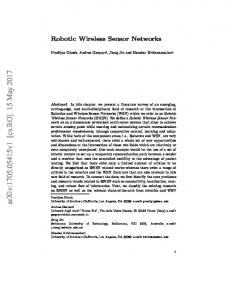
Leader
Help Center
Member
Help Request
Direction Board Guiding Path
N
K
[1, clkA] F
[0, clkA] A
[3, clkA]
[2, clkA]
P
Bi Move
B
[4, clkA]
E
[2, clkA]
J [3, clkA]
[1, clkA]
D
I
[2, clkA]
[3, clkA]
M
G
C
[3, clkA]
O
[2, clkA]
L
H
[5, clkA]
[4, clkA]
[3, clkA]
Fig. 1: System architecture.
information heavily relies on writers to write information into tags. If trackers can not gather correct pheromone information, they can not track objects correctly. Similarly, the evaporation of pheromone should be adaptively modified according to the network situations. But it also relies on objects’ and trackers’ mobility. Furthermore, since each object and tracker needs a RFID reader and writer, the hardware cost is quite high. Finally, since RFID tags have no communication capability, the concept of directions, which is realized by pheromone levels, has to be implemented at trackers’ side. These all make realizing the pheromone concept on RFID systems difficult, not to mention providing tracking services for multiple groups. III. S YSTEM A RCHITECTURE Consider a WSN deployed in a sensing field with one or multiple tourist groups. Each group has one leader and some members. Our goal is to provide the following services: (i) tracking the locations of leaders, (ii) maintaining the guiding paths to each leader, (iii) showing guiding paths for lost members, (iv) broadcasts tourist information from leaders to their members, and (v) helping leaders to recall their members. The system architecture is shown in Fig. 1. Each group leader carries a badge that can periodically emit some signals to allow the WSN to track its location. Each group member simply carries a ticket with a passive RFID tag containing his/her group ID. Each sensor node is attached to a direction board which can display simple guiding and tourist information. Some nodes in the WSN are designated as help centers, each connected to a laptop and a RFID reader. A group guiding protocol is run at each sensor node. Below, we present four service scenarios in our system: 1) Leader tracking: At normal time, each badge will broadcast signals periodically. Sensor nodes cooperate to track the locations of group leaders and maintain the guiding path from each sensor node to each leader. Examples of tracking paths are in Fig. 1. 2) Help service: When a member gets lost, he/she can go to any help center and simply present his/her ticket to the
IEEE TRANSACTIONS ON WIRELESS COMMUNICATIONS, VOL. X, NO. X, XXXX 200X
RFID reader. Then guiding directions can be shown on the screen of the help center as well as the direction boards of those sensors which form a guiding path toward the sensor that is tracking the leader. Fig. 1 shows two guiding paths from M to A and G to A. 3) Member-Recall: A group leader can also call his/her members back by pushing a button on the badge. A broadcast message will be flooded to the network. All sensors’ direction boards will show the guiding directions to the sensor which is tracking the leader. 4) Push-Message: When there is an important exhibition of presentation given by a group leader, he/she can simply push a PUSH-MSG button and related information can be flooded to the screen of all sensors. This is feasible because we track the leader’s location and thus predict his/her behaviors. Such a solution is quite feasible because only group leaders need to carry more complicated devices. RFIDs add little extra cost to our system. Our design philosophy is to reduce the management efforts. So most work is done at the infrastructure side, and only the minimum amount of devices need to be carried by users. The infrastructure cost are fixed, which include sensor nodes, direction boards, RFID readers, and help centers. The management effort only happens at the ticket booth, which includes writing group IDs into RFID tags. IV. G ROUP G UIDING P ROTOCOL (GGP) Consider a WSN deployed in an indoor environment. Each sensor knows its own location and can form wireless links with its neighbors. We also use these wireless links as guiding paths in our system. One or more tourist groups may coexist in the WSN. Each group has one leader and multiple members. Our protocol emphasizes on constructing group guiding paths and managing group mobility. We adopt a potential-based method to form guiding paths. For each wireless link, the guiding direction is from the node with a higher potential to the node with a lower one. Our design avoids using broadcast-based methods for information update. We propose a local update method to reduce the message overhead. The group guiding protocol has three basic functions: tracking group leaders, managing mobility, and providing navigation services. A. Tracking Group Leaders Our location tracking scheme relies on measuring the strengths of the signals transmitted by badges. As a result, it incurs very low complexing and low cost at users’ side. A badge only transmits signals and does not need a receiver; most work is done at the WSN side. A badge works in three states: hello, recall, and push. The recall and push states are used to activate the Member-Recall and PUSH-MSG services, respectively, which will be introduced in later section. The state transition diagram of a badge is shown in Fig. 2. In the hello state, a badge will periodically transmit HELLO packets. For each badge Bi , we will elect one sensor to monitor Bi . Each sensor in the WSN has three states: tracker, non-tracker and candidate. The sensor that is monitoring Bi is called Bi ’s tracker. (For each badge Bi , only one sensor serves
3
0
1
2
3 sec
HELLO
tracker
Ttracker, Thello, Tbid Talive, Twin
broadcast TRACKED every Ttracker sec. no BID with better RSSI is received & no TRACKED is heared & no HELLO is lost within Twin sec.
candidate
no HELLO for Talive sec.
no TRACKED within Talive sec. & continuous HELLO
non-tracker
broadcast BID every Tbid sec. TRACKED or HELLO BID with better RSSI is received || TRACKED is heared || HELLO is lost within Twin sec.
Fig. 2: State transition diagram of sensor nodes.
as its tracker, but a sensor can serve as a tracker for multiple badges.) The other sensors are non-trackers or candidates. A sensor in the candidate state is one which is trying to become a tracker. The protocol run by each sensor node Sj is outlined below. 1. When Sj is in the tracker state with respect to Bi , it will periodically broadcast a packet TRACKED(Bi , Sj ) every Ttracker seconds as long as it has heard a HELLO packet from Bi within the past Talive seconds. If Sj does not hear HELLO packet from Bi for Talive seconds, it will move to the nontracker state. 2. When Sj is in the non-tracker state with respect to Bi , it will keep on monitoring the TRACKED(Bi , Sj ) packets from Sj and the HELLO packets from Bi . However, it will move to the candidate state when the following conditions are satisfied: (i) it did not hear TRACKED(Bi , Sj ) packet for Talive seconds, and (ii) it heard bTalive /Thello c continuous HELLO packets from Bi in the past Talive seconds. Otherwise, it remains as a non-tracker. 3. When Sj is in the candidate state, it will periodically broadcast a BID(Sj , RSSI, Bi ) packet every Tbid seconds, where RSSI is the average signal strength of the HELLO packets that it heard recently. It will move to the tracker state if the following conditions are true within the past Twin seconds: (i) no BID(∗, RSSI 0 , Bi ) packet is heard such that RSSI 0 > RSSI, (ii) no TRACKED(Bi , ∗) packet is heard, and (iii) no HELLO packet from Bi is lost, where ∗ is any sensor other than Sj . If any of the above three conditions is false, Sj will move itself back to the non-tracker state. The above protocol tries to maintain at most one tracker in the network for each badge. Timers are important to maintain the correctness of the protocol. The suggested timer values are shown in Fig. 2. B. Mobility Management The above protocol can elect a tracker sensor for each badge. Next, we will develop a protocol for other sensors to trace the location of the tracker. With respect to each badge Bi , each sensor Sk will keep a potential value P oti,k . From the potentials of sensors, we can locate the tracker. Our scheme
IEEE TRANSACTIONS ON WIRELESS COMMUNICATIONS, VOL. X, NO. X, XXXX 200X
is modified from TORA [19], which is originally designed for distributed routing in mobile ad hoc networks. However, ours differs from TORA in two ways. First, tracker sensors are not static; they may change locations frequently. Second, in TORA, route requests are initiated by destination nodes, but in our system, the requests can be triggered by both group leaders and group members. Below, we will focus on one badge Bi . Each sensor keeps a neighbor table, which has six fields: badge ID, tracker ID, potential, neighbor ID, direction, and timestamp. The following protocol is executed by each sensor Sk : 1) When Sk is newly elected as the tracker of Bi , it will set its timestamp clki,k = the current clock value of Sk and its potential P oti,k = 0 and periodically transmit an UPDATE(Bi , Sk , P oti,k , clki,k ) packet, which has four fields: badge ID, tracker ID, potential and timestamp. 2) On Sk receiving an UPDATE(Bi , Sj , P ot, clk) packet from a neighbor Sb , the following steps will be executed: a) If Bi does not exist in any badge ID field of Sk ’s neighbor table, this means that Bi is a new badge entering the WSN. So Sk will add a new entry (Bi , Sj , P ot, Sb , dir, clk) into its neighbor table, where dir = Sb , which means that the direction from Sk to Sb is on the tracking path leading to Bi . Sk then updates its potential P oti,k = P ot+1 and rebroadcasts an UPDATE(Bi , Sj , P oti,k , clk) packet to its neighbors. b) If Bi already exists in one of the badge ID field of Sk ’s neighbor table but no such entries have field neighbor ID = Sb , this means that this is the first time that Sb transmits an UPDATE packet to Sk . Sk will add a new entry (Bi , Sj , P ot, Sb , dir, clk) into its neighbor table, where dir is decided as follows. If the received P ot from Sb is less than P oti,k of Sk , then dir = Sb and we set P oti,k = P ot+1. If the received P ot is larger than P oti,k , then dir = Sk and P oti,k is kept unchanged. In both cases, Sk will rebroadcast an UPDATE(Bi , Sj , P oti,k , clk) packet to its neighbors. However, if the received P ot is equal to P oti,k , then dir is set to one of Sb and Sk with a smaller ID and no broadcast will be sent. c) If an entry already exists such that badge ID = Bi and neighbor ID = Sb , Sk will compare the received clk value against the timestamp field (denoted by t) of the corresponding entry. Three cases may happen. i) If clk < t, it means that the UPDATE packet is out of date, so no action will be taken. ii) If clk = t, it means that Sb may have changed its potential value, so Sk will do the following: A) Update the corresponding entry by setting field potential = P ot and setting field direction = Sb if P ot < P oti,k and direction = Sk if P ot > P oti,k . B) Execute step 4 (the local minimum check procedure).
4
iii) If clk > t, it means that Bi has moved to a new tracker Sj , so Sk will do the following: A) Update the corresponding entry by setting field tracker ID = Sj , field potential = P ot, field direction = Sb , and field timestamp = clk. B) Set P oti,k = P ot + 1. C) Broadcast an UPDATE(Bi , Sj , P oti,k , clk) packet if field direction has been changed in the previous update. 3) We assume that each sensor node will periodically exchange BEACON(sender ID) packets with neighbors. So appearance and disappearance of links can be detected. This may trigger the following events. a) When Sk finds that its link with a neighbor Sb disappears, it will delete all entries in its neighbor table such that the field neighbor ID = Sb . This may cause Sk to become a local minimum if Sb is the only link leading to Bi . Then Sk will execute step 4. b) When Sk finds a new link to a neighbor Sb , it will broadcast an UPDATE(Bi , Sj , P oti,k , clkmax ) packet to its neighbors, where clkmax is the maximum clock value known to Sk in its neighbor table with respect to badge Bi . 4) (Local Minimum Check Procedure) If Sk which is not a tracker of Bi finds that for all entries in its neighbor table with respect to Bi , the field direction = Sk , this means that Sk is at a local minimum position. Sk will wait a random backoff time Tback seconds. In the time duration, if Sk receives no UPDATE packet that changes its local minimum situation, it will raise its potential to a local maximum by setting P oti,k = P otmax +1, where P otmax is the maximum of the potential values of all its neighbors with respect to Bi , and broadcast an UPDATE(Bi , Sj , P oti,k , clkmax ) packet, where clkmax is the maximum clock value known to Sk in its neighbor table with respect to badge Bi . Otherwise, Sk will exit this procedure. However, there is an exception in the above potential-raising procedure as noted below. In case that Bi disappears or Bi moves too fast such that no tracker can be elected during the transient period, it is impossible to find a way leading to Bi . If so, local minimum node will appear repeatedly. To solve this problem, we can set an upper bound = N on potentials, where N is the total number of nodes in the WSN. When Sk finds that P oti,k = N , it means that the network has lost the tracker. So Sk will delete all the entries with respect to Bi in its neighbor table, broadcast a CLEAN(Bi , clkmax ) packet, and stop raising the potential P oti,k until an UPDATE packet with a longer timestamp is received. We make some remarks about the above protocol. First, the guiding direction always goes from a higher potential to a lower one. So the tracker always has the lowest potential. Second, to save communication cost, this protocol does not conduct global update when a badge changes its tracker. So, a
IEEE TRANSACTIONS ON WIRELESS COMMUNICATIONS, VOL. X, NO. X, XXXX 200X
node only rebroadcasts an UPDATE packet when any direction field in its neighbor table is changed. Third, the protocol always converges as long as the badge continuously exists and a new tracker is elected to monitor this badge in the WSN (The termination of this recursion has been proved in [20].); otherwise, when any node’s potential reaches N , a CLEAN packet will be flooded to the network to clear all entries with respect to Bi at all nodes. Fig. 1 is an example when a badge Bi moves from node A to node B. Initially, node A is the tracker. The 2-tuple associated with each node is its potential and the clk value for Bi. After the movement, node B becomes the new tracker. This will cause both node A and B to send UPDATE packets. Only the direction fields of node A and B are changed. So, on receipt of the UPDATE packets, none of nodes C, D, and F will rebroadcast. C. Group Guiding Services Our system provides three services: Help service, MemberRecall, and Push Message. The Help service is to locate a member’s leader, while the Member-Recall service is for a leader to call his/her group members back. The Push Message can deliver important announcement information to members. To get Help service, a member can go to any help center, say Sk , and present his/her ticket to the RFID reader. On receiving such a request, the help center will identify the member’s group ID, say Bi , and broadcast a HELP(Bi , Sk , P ath) packet, where P ath is a null list. Any node Sj receiving a HELP(Bi , Sk , P ath) packet will look up its neighbor table. Two cases may happen. (1) If Sj can find a node Sb with the smallest potential leading to Bi , then Sj will append its ID to the P ath field of the packet and rebroadcast a HELP(Bi , Sk , P ath) packet. When the first HELP packet reaches the tracker of Bi , it will send a HELP REPLY(Bi , Sk , P ath) packet to Sk along the reverse direction of P ath. On the way back to Sk , the HELP REPLY will also trigger each node on P ath to show guiding information on its direction board. Finally, when Sk receives the HELP REPLY, guiding directions can also be shown on the help center’s screen. (2) If node Sj can not find any node Sb leading to Bi (this may happen due to packet loss), Sj will broadcast a HELP REQUEST(Bi , Sj , P ath) packet to search for leader Bi . After broadcasting the HELP REQUEST, if Sj still can not find leader Bi , there is a high probability that the leader Bi has left the network. Then Sj will send a HELP Fail(Bi , Sk ) packet back to the help center. Then the searching result also shows on the help center’s screen. The Member-Recall service is quite simple. A RECALL command will be sent to its tracker when the RECALL button of a badge is clicked. On receiving a RECALL command from a badge, the tracker of the badge will flood a SHOW(Bi ) packet throughout the network. Any node receiving such a packet for the first time will show guiding information on its direction board based on its neighbor table (which is the neighbor node with the smallest potential with respect to this badge). The Push Message is triggered by clicking on the PUSHMSG button of a badge. Then a PUSH-MSG command will be
5
sent to the badge’s tracker. The system will infer what activity the group leader is doing by his/her current location and past roaming paths. Then related announcement will be flooded to the direction boards of sensors as in the Member-Recall case. The above design is to reduce the complexity of the badges. V. S IMULATION R ESULTS To verify the effectiveness of our scheme, we have simulated a 100m × 100m area with 10×10, 30×30, and 50×50 regularly deployed nodes. The transmission range of each node is 15m. Each node has four navigation links to its neighbors, unless an out-of-boundary situation is encountered. The data rate of each node is set to 250 kbps. We also simulate different packet loss rates in our simulations. Each group has one leader and multiple randomly distributed members. Leaders will move constantly. In each move, a leader will choose one random direction and then move a pre-defined number of hops. Members will request for the group guiding service in a random manner. We compare our GGP against the shortest-path-based guiding (SP) algorithm [8], [10]. In each experiment, each case is run 50 times. In our simulation, three performance metrics are considered: • Message overhead: It involves two factors: (1) the messages required to track leaders and (2) the messages to support group guiding services. We will evaluate these two factors with different leader mobility. • Scalability: It is used to evaluate the performance of the proposed protocol in different network sizes. • Length of guiding path: This is to evaluate the routing property of the proposed protocol, which uses local updates to handle leader mobility. We first investigate the effect of leader mobility on message overhead to track group leaders. Fig. 3 shows the amount of messages needed to update leaders’ locations under different packet loss rates with 10×10 nodes. Each group has ten members, and each group leader moves 1 hop each time. For the SP method, which uses broadcast to update information, the number of packets required is equal to the network size times the number of groups (which are about 100, 200, 300, 400, and 500 messages, respectively). So the proposed protocol can significantly reduce the message overhead due to its local update property. However, the amount of packets decreases when the packet loss rate increases because a higher packet loss rate will cause some nodes to fail to receive update packets. Note that since the message overhead grows linearly with the number of groups, we will ignore this factor in the rest of our presentation. Fig. 4 investigates the effect of leader mobility on message overhead under different network sizes. We vary the number of hops that a leader can move each time when an update is conducted. The packet loss rate is set to 5%. It shows that our GGP significantly outperforms SP, especially when the network size enlarges. For example, in a 30×30 network, SP incurs 900 messages while GGP incurs about 200 messages only. Also, the gap between GGP and SP will reduce as the mobility of leaders increases, which is reasonable because our local update scheme can not handle very high mobility. These results show the scalability of our scheme.
IEEE TRANSACTIONS ON WIRELESS COMMUNICATIONS, VOL. X, NO. X, XXXX 200X
6
Fig. 5: Response time vs. Packet loss rate. Fig. 3: Message overhead vs. Number of groups.
Fig. 4: Message overhead vs. Leader mobility.
Next, we try to use some simulation technologies to change the network topology. Specifically, we randomly generate some rectangles as obstacles in our grid network, where each rectangle is of size 2×4 or 4×2. More obstacles mean a higher possibility that a packet has to route-around obstacles to reach it destination. Note that our simulations will ignore those cases which obstacles partition the network. First, we compare the request response time in different network sizes and packet loss rates. The request response time is calculated from the time from a member sending a request packet to a search result coming back. Since more obstacles and a higher packet loss rate will cause longer guiding paths, we see higher response time in networks with obstacles, as shown in Fig. 5. The packet loss rate is set to 5%. However, as shown in Fig. 6, the number of messages for tracking leaders actually decreases as the number of obstacles increases because obstacles will decrease the number of nodes in the network. Since our scheme uses only local update, it could lead to non-optimal guiding paths. We define the average excess hops (AEH) as the average difference of GGP’s path length and SP’s path length. In Fig. 7, we simulate different network sizes with various packet loss rates and numbers of obstacles (each as a 2×4 or 4×2 rectangle). Each group has five members. Members may need to route-around obstacles to find their leaders. Generally, a higher packet loss rate will increase the
Fig. 6: Impact of obstacles on message overhead.
lengths of guiding paths because a missing UPDATE packet may further detour some guiding paths. However, as there are more obstacles, the effect is less significant because SP will also suffer from packet loss. With more obstacles in smallscale network, the SP may even find larger paths than GGP because it always tries to update the whole paths as leader move around; therefore, as there are more and more obstacles it is more likely to incur non-optimal route-around paths. From Fig. 7, we see that the values of AEH are all quite small, which further shows the scalability of our results. Because our scheme broadcasts HELP REQUEST to find leaders when a node’s neighbor table is out-of-date due to packet loss, we further include such overhead in our comparison. In Fig. 8, we vary network size, packet loss rate, and number of obstacles to observe the effect. Note that here we include all leader-tracking and group-guiding messages. We see that GGP outperforms SP except when the network is very large and the packet loss rate is very high. We summarize three points from the above performance results: (1) The local update mechanism is quite effective. (2) The proposed scheme scales well to number of groups, size per group, and network size. (3) Even under packet loss situations, the proposed protocol sill works quite efficiently.
IEEE TRANSACTIONS ON WIRELESS COMMUNICATIONS, VOL. X, NO. X, XXXX 200X
7
Leader location Leader badge
Fig. 7: Impact of packet loss rate on AEH.
Fig. 9: A prototyping system: an example of Member-Recall services. Power Supply
Control Buttons
Switch Circuit
LED Matrix Buzzer
XC2C128 commands Control Module
XC2C128 Buzzer
Control Buttons
MICAz LED Matrix
Fig. 10: Design of leader badge and direction board. Fig. 8: Overall message overhead vs. Packet loss rate. VI. P ROTOTYPING E XPERIENCES We have developed a small-scale prototype of the proposed system with 16 MICAz motes, one help center, and one leader badge, as Fig. 9 shows. The network control module and our group guiding protocol are realized by motes. The group guiding protocol can be verified by checking the LEDs on sensor nodes. The DIP switches on the leader badge are to change its states. A. Leaders’ Badges Each badge will periodically broadcast signals for the WSN to track its location. Our implementation adopts audio signals to keep cost low, but it can be easily extended to other signal sources. A badge is composed of a buzzer, a switch circuit, a control module, some control buttons, and a power supply, as shown in Fig. 10. The buzzer can transmit 4 kHz sound in a certain pattern specified by the control module. The switch circuit passes control messages from the control module to the buzzer. The control module is implemented by a Xilinx XC2C128 chip, a low power chip operating at 1.5V. The overall cost per badge is less than 10 US dollars. We also use audio signals to carry digital data based on a simple amplitude modulation (AM) at a rate of 2 bits/sec. Each packet has three fields: preamble, command, and group ID. There are three commands, HELLO, RECALL, and PUSHMSG. A badge also works in three states: hello, recall, and push. In the hello state, it will periodically transmit a HELLO
command for sensors to locate it. When the group leader needs to recall its members or push messages, he/she can push a control button and the badge will switch to the recall/push states, transmit RECALL/PUSH-MSG commands for a short period of time, and then go back to the hello state. Since the control module is programmable, more commands can be added easily. B. Sensor Nodes and Direction Boards The sensor nodes are realized by MICAz motes, which can sense sounds through their microphones. Audio signals received by a microphone can be fed into a tone detector, which can identify whether the audio signal is 4 kHz or not and then respond a digital high or low output, by which digital data is decoded. Each sensor node is connected to a direction board, which contains an 8×8 LED panel, as shown in Fig. 10. Implemented by a Xilinx XC2C128 chip, the control module is connected to the sensor node via a 51-pin connector. LEDs has two colors: red is for lost members and green is for recalling members and pushing messages. Direction boards can support “on-site” visualization. Our current implementation can display group IDs, guiding directions, and simple information interchangeably, as shown in Fig. 11. Since the control module is programmable, further extensions can be added easily. This is quite attractive as opposed to traditional guiding devices, which can only show fixed directions. In fact, it is the information from the WSN that enriches the displayed contents.
IEEE TRANSACTIONS ON WIRELESS COMMUNICATIONS, VOL. X, NO. X, XXXX 200X
Leader location
GUI Member/Group information
Group ID
Direction
Fig. 11: Help service and GUI. Group X Database
Group Y 1xxx
2xxx
1xxx
2xxx
1xxx
2xxx
SQL Server Network Help Center RFID Tag command
RFID Reader
location
WSN Mote
Laptop
Fig. 12: Help center.
C. Help Centers A help center is a laptop connected to a sensor node and a RFID reader, as shown in Fig. 12. We adopt the A9280-B RFID reader by AMIC Tech. Inc. [21], which is compatible with ISO 15693 standard. The mappings between tags and group IDs are stored in a Microsoft SQL server. We design two user interfaces. One is the administrative interface (for use in ticket booths) for managing the mapping between group ID and tag ID. Each RFID tag has a storage capacity of 1024 bits to record group information, such as group ID, group name, leader name, and member name. The other is the user interface (for use in the help centers), as shown in Fig. 11. The lower part contains the member/group information and the upper part shows the navigation information. Help centers provide two major services. First, given a group ID, it will find the location of the group leader and then request sensors on the path toward the leader to display instructions on their direction boards. Therefore, a lost member can easily find his/her leader. Second, the navigation paths will also be shown on its screen so that the user can have a global view on the leader location. Traditional help centers are usually located in limited areas such as entrances. Enabled by pervasive sensing and communication technologies, our system can virtually deploy help centers everywhere.
8
D. Experimental Experiences We have developed a small-scale prototype on a floor in a campus building, as shown in Fig. 9. The prototype consists of 16 MICAz motes, one leader, and one help center. Each node is connected with a direction board. Sensor nodes can be deployed on walls or corridors with real-time guiding directions on their direction boards. Note that some manual processing is needed to match physical links with navigation links (which means that some physical links have to be removed on purpose). After deployment, we can start the system. The help center is located at the lower part of the map. Each leader badge and RFID tag are synchronized in the ticket booth to form a group before entering the system. Below, we show two services. The first one is the user-based guiding service. When a user triggers the Help service at the help center, guiding information will be shown on the direction boards of nodes along the guiding paths and the GUI on the help center, as shown as Fig. 11. The LED panel shows group ID and guiding direction interchangeably and periodically, where the period is set to one second. The tracker node of the leader will interchangeably show its group ID and a letter L, which means leader. The second one is the MemberRecall service, as shown in Fig. 9, where all nodes are pointing toward the leader. VII. C ONCLUSIONS We have proposed a framework to support group guiding services based on existing RFID and WSN technologies. Such new services can be applied to group tourist activities and enrich tourists’ experiences. Simulation results show that the proposed protocol can reduce the message overhead when updating the network management information and can support different number of groups. The framework places special emphasis on the feasibility of the model, so what a member needs to carry is only a RFID-tagged ticket and what a group leader needs to carry is a badge with some simple buttons. This could minimize the management efforts and simplifies the user interface part. Although our current prototyping only contains very brief guiding information, we believe that it can trigger more services with richer contents. The group guiding system can be extended to provide more services. Potential challenges for future study include people/object searching and emergency guiding services. People/object searching is an interesting problem, which should consider the people-topeople, people-to-object, and people-to-group relations. And the People/object searching problem can be intra-group or inter-group. We believe that our work can be a fundamental block to further research in these directions. ACKNOWLEDGMENT The authors would like to thank Cheng-Han Wu and LiChun Chen for their supports in system implementation, and Chi-Han Lin for his support in simulation. This work is supported in part by NSC Grants 97-2219-E-007-004, 97-2219-E007-001, and 97-2221-E-007 -037. Y.-C. Tseng’s research is co-sponsored by MoE ATU Plan, by NSC grants 95-2221-E009-058-MY3, 96-2218-E-009-004, 97-3114-E-009-001, 972221-E-009-142-MY3, and 97-2218-E-009-026, by MOEA
IEEE TRANSACTIONS ON WIRELESS COMMUNICATIONS, VOL. X, NO. X, XXXX 200X
under grant 94-EC-17-A-04-S1-044, by ITRI, Taiwan, and by III, Taiwan. R EFERENCES [1] P. Y. Chen, W. T. Chen, C. H. Wu, Y.-C. Tseng, and C.-F. Huang, “A group tour guide system with rfids and wireless sensor networks,” in Int’l Conference on Information Processing in Sensor Networks (IPSN), 2007, pp. 561–562. [2] R. Weinstein, “RFID: a technical overview and its application to the enterprise,” IEEE IT Professional, vol. 7, no. 3, pp. 27–33, May 2005. [3] I. Akyildiz, W. Su, Y. Sankarasubramaniam, and E. Cayirci, “A survey on sensor networks,” IEEE Communications Magazine, vol. 40, no. 8, pp. 102–114, Aug. 2002. [4] M. Tubaishat and S. Madria, “Sensor networks: an overview,” IEEE Potentials, vol. 22, no. 2, pp. 20–23, Apr/May 2003. [5] Louvre Museum, “Frence,” http://www.louvre.fr. [6] Nation Palace Museum, “Taiwan,” http://www.npm.gov.tw. [7] P. Corke, R. Peterson, and D. Rus, “Localization and navigation assisted by cooperating networked sensors and robots,” Int. Journal of Robotics Research, vol. 24, no. 9, pp. 771–786, Oct. 2005. [8] Q. Li, M. Rosa, and D. Rus, “Distributed algorithms for guiding navigation across a sensor network,” in ACM Int’l Conf. on Mobile Computing and Networking (MobiCom), 2003, pp. 313–325. [9] C. Buragohain, D. Agrawal, and S. Suri, “Distributed navigation algorithms for sensor networks,” in IEEE INFOCOM, 2006. [10] Y.-C. Tseng, M.-S. Pan, and Y.-Y. Tsai, “A Distributed Emergency Navigation Algorithm for Wireless Sensor Networks,” IEEE Computers, vol. 39, no. 7, pp. 55–62, July 2006. [11] M. Mamei and F. Zambonelli, “Programming pervasive and mobile computing applications with the tota middleware,” in Proceedings of the Second IEEE International Conference on Pervasive Computing and Communications (PerCom’04), Washington, DC, USA, 2004, p. 263. ´ [12] M. Mar´oti, P. V´olgyesi, S. D´ora, B. Kusy, A. N´adas, Akos L´edeczi, G. rgy Balogh, and K. Moln´ar, “Radio interferometric geolocation,” in ACM Int’l Conf. on Embedded Networked Sensor Systems (SenSys), Nov. 2005, pp. 1–12. [13] K. D. Frampton, “Acoustic self-location in a distributed sensor network,” IEEE Sensor Journal, vol. 6, no. 1, pp. 166–172, Feb. 2006. ´ [14] Akos L´edeczi, P. V´olgyesi, and M. Mar´oti, “Multiple simultaneous acoustic source localizationin urban terrain,” in Int’l Conference on Information Processing in Sensor Networks (IPSN), 2005, p. 69. [15] S.-P. Kuo and Y.-C. Tseng, “A scrambling method for fingerprint positioning based on temporal diversity and spatial dependency,” IEEE Trans. on Knowledge and Data Engineering, vol. 20, no. 5, pp. 78–684, 2008. [16] ExSal mote, “www.cast.cse.ohio-state.edu/exscal/index.php.” [17] VigiNet, “www.cs.virginia.edu/wsn/vigilnet/index.html.” [18] M. Mamei and F. Zambonelli, “Pervasive pheromone-based interaction with rfid tags,” ACM Trans. Auton. Adapt. Syst., vol. 2, no. 2, p. 4, 2007. [19] V. D. Park and M. S. Corson, “A highly adaptive distributed routing algorithm for mobile wireless networks,” in IEEE INFOCOM, 1997, pp. 1405–1413. [20] E. M. Gafni and D. P. Bertsekas, “Distributed algorithms for generating loop-free routes in networks with frequently changing topology,” in IEEE Trans. Commun., vol. 29, no. 1, Jan. 1981, pp. 11–18. [21] AMIC Tech. Inc., “http://www.amictechnology.com/.”
Po-Yu Chen received his B.S. degree from the Department of Electrical Engineering, Chang Gung University (CGU), Taiwan in 2001 and M.S degree from the institute of communications engineering, National Tsing-Hua University, Taiwan in 2003. He is now a Ph.D. candidate. He was a summer intern at Telcordia Technologies, Piscataway, NJ, USA in 2007. His research interests include wireless communication, protocol and algorithm design, and mobile computing, especially in Ad Hoc and Sensor Networks.
9
Wen-Tsuen Chen received the B.S. degree in nuclear engineering from National Tsing Hua University, Taiwan, Republic of China, and the M.S. and Ph.D. degrees in electrical engineering and computer sciences both from University of California at Berkeley, in 1970, 1973, and 1976, respectively. He has been with the National Tsing Hua University since 1976 and is currently a Distinguished Chair Professor of the Department of Computer Science and the President of the University. He has served as Department Chairman, Dean of College of Electrical Engineering & Computer Science, Director of Science & Technology Advisory Office, Ministry of Education, Taiwan, and Vice Chancellor (Research) of the University System of Taiwan. He has consulted in various levels of Taiwan Government and served as a member of many planning and technical review boards. For 14 years, Professor Chen has served as CoChairman and Chairman of the Technical Evaluation Board of the Ministry of Economic Affairs for Promoting High-Tech Products and Technologies, which is recognized as most pivotal in promoting industrial technologies in Taiwan. His research interests include computer networks, wireless Internet, multimedia communications, and parallel algorithms. Professor Chen pioneered the design of computer networks and parallel systems in early 1980s. He is currently leading a project for design and applications of advanced information networks. He has received numerous awards for his achievements in computer networking and parallel processing, including Outstanding Research Awards of the National Science Council, Academic Award and National Chair of the Ministry of Education, and Technical Achievement Award of the IEEE Computer Society. In 1984, 1993, and 1995, he served as an IEEE Distinguished Visitor in region 10. He has also served as a member of the Board of Directors of the IEEE Taipei Section. Professor Chen was the General Chair of the 2000 IEEE International Conference on Distributed Computing Systems and the Founding General Chair of the IEEE International Conference on Parallel and Distributed Systems. He is an IEEE Fellow and a Fellow of the Chinese Society for Management of Technology.
Yu-Chee Tseng obtained his Ph.D. in Computer and Information Science from the Ohio State University in January of 1994. He is Professor (2000preset), Chairman (2005-present), and Associate Dean (2007-present) at the Department of Computer Science, National Chiao-Tung University, Taiwan. He is also Adjunct Chair Professor at the Chung Yuan Christian University (2006-present). Dr. Tseng received the Outstanding Research Award, by National Science Council, ROC, in both 2001-2002 and 2003-2005, the Best Paper Award, by Int’l Conf. on Parallel Processing, in 2003, the Elite I. T. Award in 2004, and the Distinguished Alumnus Award, by the Ohio State University, in 2005. His research interests include mobile computing, wireless communication, and parallel and distributed computing. Dr. Tseng serves on the editorial boards for Telecommunication Systems (2005-present), IEEE Trans. on Vehicular Technology (2005-2009), IEEE Trans. on Mobile Computing (2006-present), and IEEE Trans. on Parallel and Distributed Systems (2008-present).
Chi-Fu Huang is currently an Assistant Professor in the Department of Computer Science and Information Engineering, National Chung Cheng University, Taiwan, since Feb. 2009. Prior to joining CCU, he was a Research Assistant Professor at the Department of Computer Science, National Chiao-Tung University, 2005 - 2009. Dr. Huang received his B.S. and M.S. degrees from the Feng-Chia University and the National Central University in 1999 and 2001, respectively. He obtained his Ph.D. in Computer Science and Information Engineering from the National Chiao-Tung University in Sep. 2004. He was a visiting scholar in the Ohio State University, USA (Sep. 2006 - Nov. 2006). His research interests include wireless communication and mobile computing, especially in Ad Hoc and Sensor Networks.