Providing Time- and Space- Efficient Procedure Calls for
Recommend Documents
Sep 8, 2009 - implemented as part of a wireless Local Area Network (LAN) or Metropolitan ...... computer-readable storag
Sep 8, 2009 - âChannel Estimation for OFDM Systems With Transmitter Diversity in Mobile Wireless .... transmission lin
Jun 2, 1987 - WEISS AND ALLAN: NBS CALIBRATION PROCEDURE schedule tells ..... [3] J. E. Gray and D. W. Allan, âA method for estimating the frequency.
dure Calls (TPC), a runtime system for supporting task-based program- ming models ... information for efficient execution and runtime optimization. Thus ...... Center (BSC) and the Polytechnic University of Catalonia (UPC) for making available ...
It also describes how interrupts and exceptions are handled from the perspective
of an ..... See Chapter 15, 8086 Emulation, in the Intel Architecture Software ...
transfers, exceptions, process switches) in a uniform way. ... This cost depends on three things: ... general control transfers (§ 3), and then describe several.
programmer explicitly coding the details for this remote interaction." .... BSD socket API. Argus, a language/system for
Jun 28, 2006 - Simi- lar variations in the level of accuracy required are seen in analyzing massive data streams: for example, in monitoring performance in.
Abstractâ This paper presents a solution to efficiently explore the design space of communication adapters. In most digital signal processing (DSP) applications, ...
Nov 29, 2017 - Law Group, to John J. Canary and Jeffrey J. Turner,. Office of Regulations and .... changed since then to
May 28, 1997 - and allows the programmer to use the familiar shared memory model. However, this ease of ..... responsibility for the application programmer.
May 28, 1997 - To this end we have evaluated and compared the three paradigms. .... passing; remote procedures are called in a similar way to local ...
The least median of squared residuals regression line (or LMS line) is that line y = ax + ..... the LMS regression line l...a is that the number K of points between L1 ...
Abstract. String editing problem is one of the most fundamental problems in
computer science ... However it does not address the problem of computing the
edit.
Page 1 ... with n characters, building a suffix tree takes O(n) time, then a pattern P can be located in O(|P| + occ) time, where occ is the number of occurrences.
on compressed suffix arrays, which reduces the space requirement from ... Arrays (CSA) proposed by Grossi and Vitter [7], and the FM-index proposed ...... Ψ function of T, we can construct the FM-index of T in O(n) time using O(n log|Σ|) bits in.
probabilities also act as a measure of soft error susceptibility (an increased threat in nano-domain logic block) that depends on the structural correla- tions of the ...
Sep 11, 2015 - for tetrahydropyranylation, peroxy-λ 3-iodane/ CCl4. [14] for tetrahydrofuranylation, I2 [15], α-Zr(O3. PCH3)12(O3PC6H4SO3H)0.8 [16] and ...
formation of diazonium salt was confirmed by a test with β-naphthol. When the diazotization was complete, potassium iodide (5 mmol) was added to the paste- ...
of the EDF calculations in spatially homogeneous RF fields. moving .... If it is possible to neglect the energy losses in elastic collisions eo ... right-hand side of (4) (it's determined by slow electrons that ..... Surprising is the close coinciden
Mobile technologies and the cultural patterns of their usage have evolved at a tremendous speed .... actual differences between landline and mobile calls (see Arminen ...... Paper presented at the ISA World Conference, Durban, July 22-29.
Mobile Time-Space â Arena for New Kinds of Social Actions. Ilkka Arminen, University of Tampere. At the millennium, when I became involved with research on ...
initialization requirements undermine the central goal of RPC programming: transpar- ent distributed computing. We present a remote procedure call package ...
space-time codes (STC) have been introduced to use space as a second dimension of coding. Layered space-time (LST) codes are a special kind of STC.
Providing Time- and Space- Efficient Procedure Calls for
Sep 22, 2004 - choosing a subset of calls to inline and to remove the timing .... secondary thread, ensuring that running any segment of the .... The tight coupling of input and output ...... transition-diagram compiler,â Communications of the.
Providing Time- and Space- Efficient Procedure Calls for ∗ Asynchronous Software Thread Integration Vasanth Asokan and Alexander G. Dean Center for Embedded Systems Research, Department of Electrical and Computer Engineering, North Carolina State University, Raleigh, NC 27695-7256 alex [email protected] ABSTRACT
General Terms
Asynchronous Software Thread Integration (ASTI) provides fine-grain concurrency in real-time threads by statically scheduling (integrating) code from primary threads into secondary threads, reducing the context switching needed and allowing recovery of fine-grain idle time. Unlike STI, ASTI allows asynchronous thread progress. Current ASTI techniques do not support procedure calls in the secondary thread because they lead to timing conflicts during static scheduling. ASTI requires knowing the secondary thread’s instruction execution schedule to guide placement of real-time instructions from the primary thread. A secondary thread procedure called from multiple sites will have ambiguous timing at compile time. In this paper we remove this constraint using both procedure inlining and cloning. We present a formal approach to choosing a subset of calls to inline and to remove the timing conflicts in the remaining call sites in an efficient fashion. Excessive inlining and cloning both lead to code size explosion, while poor choices in timing conflict elimination slow program execution. The cloned threads show a significant speedup when compared to non-cloned versions yet have low code expansion. The techniques presented here have been implemented in our post-pass compiler Thrint and demonstrated on a benchmark suite of secondary threads representative of low-end embedded systems.
Algorithms, Design, Experimentation
Categories and Subject Descriptors D.3.4 [Programming Languages]: Processors—code generation/compilers/optimization; D.4.1 [Operating Systems]: Process Management—concurrency/multitasking/scheduling/ threads; D.4.7 [Operating Systems]: Organization and Design—real-time systems and embedded systems ∗Sponsored by NSF CAREER award CCR-0133690
Permission to make digital or hard copies of all or part of this work for personal or classroom use is granted without fee provided that copies are not made or distributed for profit or commercial advantage and that copies bear this notice and the full citation on the first page. To copy otherwise, to republish, to post on servers or to redistribute to lists, requires prior specific permission and/or a fee. CASES’04, September 22–25, 2004, Washington, DC, USA. Copyright 2004 ACM 1-58113-890-3/04/0009 ...$5.00.
Keywords Asynchronous software thread integration, hardware to software migration, fine-grain concurrency, software-implemented communication protocol controllers, J1850
1. INTRODUCTION The problem of efficiently allocating a number of concurrent potentially real-time tasks onto one or a few processors is important to the fields of real-time and multiprocessor scheduling, hardware/software co-synthesis and compilation. Dynamically scheduling and then performing each context switch consume time, reducing system throughput. However, embedded systems designers can sometimes take advantage of application information to statically schedule or even eliminate context switches. This reduces the instruction throughput required, allowing the use of a slower processor clock or even a less complex and less expensive processor. Slower processors have a lower demand for instruction and data throughput, potentially averting the need for memory hierarchies, superscalar instruction issue and branch prediction. Using a processor without such features simplifies system design, performance prediction and analysis. Lower clock rates lead to benefits such as reduced power and energy consumption, reduced electromagnetic emissions and susceptibility, easier hardware design and debugging, and simplified power supplies and distribution networks. One example of an embedded application subsystem with frequent context switches which can be reduced significantly is a dedicated communication protocol controller. Hardware to software migration of such a device can improve system cost, size, weight, power, time to develop and upgradeability. For example, although the CAN automotive protocol [1] has been standardized since 1991, it has taken a decade for it to become a common peripheral on low-cost microcontrollers. Until recently designers had to buy dedicated CAN controllers which often cost at least as much as the microcontroller to which it was a peripheral. The processing needed per bit for common embedded network protocols is typically quite small, ranging from 10 to 200 instruction cycles [2–6]. Given the means to achieve adequate concurrency, a simple and inexpensive microcon-
troller running at a clock frequency of tens to hundreds of times the network bit rate could implement these protocols and perform other processing as well. 8 and 16 bit microcontrollers with clock rates of 1 MHz to 100 MHz are quite inexpensive, with prices ranging from $0.25 (US) to $5.00 (US). ASTI can make it possible to use these MCUs efficiently enough for this application, eliminating the need for faster processors and their determinism-sapping microarchitectural features such as caches, superscalar execution and branch prediction. These microcontrollers are low in cost in comparison with discrete network interface ICs or network processors, offering cost savings on top of flexibility. We call such migrated devices software-implemented communication protocol controllers (SWICPCs); they feature one or more real-time threads which access to the network bus and are characterized by fine grain idle time imposed upon them due to the bit rate of the protocol. Although this paper concentrates on SWICPCs, these methods are applicable to the other fields mentioned earlier, especially hardware/software co-synthesis.
1.1 ASTI Software Thread Integration (STI) [7] and Asynchronous STI (ASTI) [8] are compiler methods which interleave functions from separate program threads at the assembly language level, creating implicitly multithreaded functions which provide low-cost concurrency on generic hardware. STI provides synchronous thread progress, requiring the software developer to gather work to ensure an integrated function is frequently data-ready. ASTI provides asynchronous thread progress through the use of lightweight context switches (coroutine calls [9]) between primary and secondary threads. Each thread has its own call stack. The primary thread has hard-real-time constraints, unlike the secondary thread. (We leave analysis of a secondary thread’s real-time characteristics for future work.) In ASTI, the cost of context switching is mitigated by reducing the number of these switches, as shown in Figure 1. ASTI uses the idle time TIdle within a frequently-called primary thread function as a window in which to execute a segment of a secondary thread via a coroutine call (or cocall ). There will be TSegmentIdle = TIdle − 2 ∗ TCocall of that time available, given that two cocalls (TCocall long each) must execute for each segment. After padding to equalize timing of conditionals and loops modulo TSegmentIdle , the entire secondary thread is broken into segments of duration TSegmentIdle . Intervening primary code within the idle time window is removed and integrated into each segment of the secondary thread, ensuring that running any segment of the secondary thread will still result in the proper intervening primary code executing at the correct times. In addition, coroutine calls are integrated in the secondary thread to ensure that it yields control back to the primary thread at the end of the segment, just before the available idle time expires. The coroutine calls are responsible for saving the context of one thread before switching to the other during the idle time slots. These two types of code are integrated by copying them into each path of control flow in a location which ensures they execute at the correct times regardless of the primary and secondary thread’s progress. Conditionals in the primary code and secondary thread segments are padded to eliminate timing jitter, the code is statically analyzed for
timing behavior, and then the primary code regions are inserted at the appropriate times. Integration involves controldependence graph traversal, and transformations are cumulative. Non-looping primary code regions are handled individually. Moving a region into a conditional requires replicating it into both sides, while entering a loop requires either guarding the execution with a conditional which triggers on a specific loop iteration or else splitting and peeling the loop. Looping primary function regions are unrolled and treated as non-looping regions unless they overlap with secondary function loops. In the latter case the overlapping iterations of the two loops are unrolled as needed to match the secondary function loop body work to available idle time in the primary function loop body. This increases efficiency. In certain cases, integrated code may be guarded by a conditional test to allow execution based upon mode flags in a status register. More details appear in [8]. We assume that instructions take a predictable number of cycles to execute. We target applications with only one hard real-time thread (the primary thread, used for the communication protocol), although recent extensions to STI [13] support multiple hard-real-time primary threads. During message transmission or reception, any other (secondary) threads will only run in the available idle time, slowing them from their original speed. (Note that this is an improvement over the non-integrated case, where threads may be completely blocked). These methods eliminate most of the context switches needed to share the processor, enabling recovery of finergrain idle time for use by the secondary thread. The two benefits of these recovered compute cycles are improved performance of the secondary thread and reduced minimum clock speed for the microprocessor. The former allows more work to be done, while the latter enables the use of a lower cost processor or a more power-efficient operating frequency. These benefits enable embedded system designers to use existing processors more efficiently with less software development effort. Designers can implement their communication software methodically without resorting to ad hoc solutions which are brittle and difficult to change.
1.2 Motivation Procedure calls in the secondary thread code complicate the insertion of cocalls at periodic intervals. This is illustrated in Figure 2. Performing a pass through the secondary thread’s control flow, cocalls are inserted in the secondary thread every TSegmentIdle cycles, based upon the staticallydetermined schedule. The number of cycles remaining before the next cocall is called the phase Φ at that point. Each procedure call site will have a certain Φ. If there are multiple call sites to a procedure, then there could be multiple values of Φ at the start of the procedure’s control flow, depending upon the origin of the call. Thus there is a conflict in the schedule inside the body of the procedure. Referring to Figure 2, given a TSegmentIdle of 50 cycles and two calls to SampleProc, then Φ1 is 10 and Φ2 is 30. Correspondingly, a cocall needs to be placed at either 40 cycles or 20 cycles into the procedure, based on the origin of the call. The same conflict extends to placing the intervening primary code (removed earlier) that follows a certain offset from each cocall. Existing ASTI methods constrain the secondary thread from having procedures and procedure calls. This paper’s methods remove this limitation.
Executive ReceiveMessage ReceiveBit
Idle time
Check for errors, save bit, Return update CRC
Prepare message Read bit from bus Sample bus for buffer 3 times and vote resynchronization a) Timeline of original primary thread execution
Primary Thread Secondary Thread
Executive ReceiveMessage ReceiveBit
Coroutine calls
b) Idle time recovered with coroutine calls ASTI Primary Thread Integrated Secondary Thread
Executive ReceiveMessage ReceiveBit c) Idle time recovered with coroutine calls and integration
Figure 1: Traditional method for sharing processor incurs two context switches per idle time fragment. ASTI eliminates most context switches and also recovers finer grain idle time.
A statically predictable schedule can be derived for procedurized code by adding padding cycles at each call site to pad the Φ at the call site to the worst case. Referring to the same example, adding 20 cycles of padding before the first call site would bring both the Φs to the same value (30), thus removing the conflict. Padding cycles waste time and get progressively worse when there are many call sites. The effect of padding cycles during run-time depends on the dynamic invocation frequency of the call site and could be much worse (e.g. a call site in a loop). Procedure inlining can be used to remove the timing conflict problem; with inlining, each call site is replaced with the body of the procedure. We have adopted an approach that removes procedure calls efficiently while adhering to a code expansion limit. For those procedures where inlining is not a viable alternative, the phase Φ at each call site is padded to the worst case. At this stage, procedure cloning can be applied. Cloning creates multiple versions of a procedure, each optimized differently to match a calling site’s characteristics better. We use cloning to cluster call sites to minimize the amount of padding cycles added, and therefore improve secondary thread throughput over non-cloned versions. We apply these methods to three different benchmark secondary threads representative of the high-volume, low-cost portion of the embedded market - a host microcontroller-toprotocol controller interface thread, a “smart node” thread and a closed loop PID controller thread. The tradeoffs between code size and wasted processor cycles, are analyzed and speed-ups due to cloning are evaluated. We use static rather than dynamic heuristics to guide our inlining and cloning for two reasons. First, gathering profile information for low-end embedded systems is not as straightforward as with workstations. One problem is the limited writeable memory (e.g. 4 kilobytes of RAM in our application) and the lack of a file system. A bigger problem is that embedded systems interact closely with their environments, often requiring a closed-loop approach. For example, embedded network protocols with bitwise arbitration require the
Figure 2: Where should a coroutine call be placed in a procedure called by multiple program locations? Inlining bloats code size while padding slows down thread progress. Our approach leverages cloning to balance the two.
controller to sample a bus after each transmission to detect lost arbitration. Error flags may also need to be detected while transmitting. The tight coupling of input and output operations makes the stimulus/log file approach of typical simulators excessively constraining, due to the overwhelming number of files which must be generated and managed. Second, this work is our initial solution to the problem of allowing procedure calls in secondary threads. Future work may optimize it by using profile guidance. We expect the performance penalty is acceptable; recent work showed a mean performance penalty of 24.4% when inlining based on static rather than dynamic call graphs [10]. Although this figure is large, it is moderate considering the secondary thread speedup acheived using ASTI (e.g. 100%) [8].
1.3 Paper Overview This paper is organized as follows. Section 2 discusses the new methods for efficent inlining, cloning and padding. Section 3 describes the experiments performed and their results. Section 4 describes related work in compiler methods to cut context switching overhead and also methods for procedure inlining and cloning. Section 5 describes the impact of the results and future opportunities.
2. METHODS Procedures are supported using two processing phases. In the first phase, a set of call sites is chosen to be removed through procedure inlining. This is because, typically, there will be some amount of code expansion that can be tolerated by the system at hand. Call sites which are not inlined have to be cloned and handled. Therefore, for a given code size constraint, the initial phase will have to remove as many call sites as possible through procedure inlining. The second phase will transform the remaining procedures and calls so that cocalls and primary thread code can be integrated. Procedure calls with similar timing characteristics are clustered together to call a single procedure clone, minimizing the time wasted in padding.
Set 1
2.1 Phase One The goal of the first phase is to minimize the number of call sites while meeting a code expansion limit. From the point of view of the inlining decision, all call sites have the same relative benefit. This reduces the problem to the easy 0/1 knapsack problem, for which a linear time solution exists. In this case, the optimal solution is to sort the items in order of increasing cost and insert them into the knapsack in this order until nothing fits. But such an easy solution cannot be adopted because of the problem of mutual dependence of call sites. Choosing to inline a particular call site may produce new call sites, which essentially changes the number of items in the knapsack formulation. Also, while inlining call sites which are nested, the code size (cost) of the outer procedure will grow. These issues are not addressed in traditional knapsack formulations. Procedure inlining under a code expansion constraint for embedded systems is discussed in [11]. The core of the solution is a branch and bound algorithm for minimizing the number of dynamic calls, while satisfying a code expansion constraint using procedure inlining. The algorithm allows an exploration of the entire solution space in a comparatively shorter time. Branch and bound algorithms work by starting at the root problem and applying known lower and upper bounds. If the problem exceeds the bounds, then it is cut off from the search space. If the solution space satisfies either of the bounds the solution space is partitioned into two and the two spaces are recursively examined in the same way. The technique presented in [11] seeks to minimize the dynamic call frequency. This method is adapted here to use static call information (N (fi ), the number of static calls to a given function) to guide inlining rather than dynamic information (D(fi )) in that work. A Boolean inlining decision is reached for each procedure – either the procedure is inlined or it is not. If each procedure forms a bit in a bit vector, then the algorithm attempts to assign values to each bit such that the total number of static call sites is minimized. As stated earlier, we use static rather than dynamic call information due to the complexity of profiling deeply-embedded, tightly-I/O-coupled code on small microcontrollers. There are several factors to note about this approach. First, either all calls to a procedure are inlined or none are. This is an acceptable simplification for our purposes. Second, traditional algorithms for the Knapsack problem cannot be used because of the previously described mutual interdependence of the call sites. Third, the modified algorithm aims to minimize the number of static call sites. Based on the current configuration of the inlining vector IV , new static call sites could be created. Hence changes in IV will have a global effect not only on total code size (S(IV )) but also on the number of static calls (N (IV )). To counter this, IV represents the procedures in the system in reverse topological order.
2.2 Phase Two Some procedures may have not been inlined after phase one due to code size limits. Calls to these procedures must “share” them and hence may need to be delayed so that the desired cocall location overlaps, avoiding the conflict shown in Figure 2. The naive approach is to pad each call site to occur at the same worst-case time. The goal of phase two is to minimize the time executing such padding by grouping
Figure 3: Phase Φi of procedures vary with time since last cocall before call site. Clustering reduces variance and time wasted in padding.
calls with similar phases and cloning the procedure for each group. We define the phase Φi of a procedure call site i as the number of cycles between the procedure entry and when the next coroutine call must be executed. The worst-case phase ΦW C of a given procedure’s call sites is the minimum Φi ; other call sites must be padded to match this one. The mean phase cannot be chosen, as the calls with later phases will have incorrect timing. Figure 3 shows an example of the phases of six call sites to a given procedure. If all call sites target the same procedure, they will all be padded to match the worst case phase ΦW C1 of 20 cycles. As a result the total padding needed is 275 cycles (static). However, we can group the calls into one set, padded to ΦW C1 , and another set, padded to ΦW C2 . A clone to service the second set can then be created, reducing the total padding required to 105 cycles. Grouping the calls into three sets and creating a second clone would reduce the total padding to 45 cycles, at the expense of additional code expansion. The amount of clones generated for each procedure can be controlled by the Clone Ratio (CR). Given that Nc is the number of clones created and Ncs is the number of call sites which target the procedure, each procedure’s clone ratio can be defined: Nc CR = Ncs Thus the clone ratio can vary from a maximum of 1, which indicates there is a clone for each call site to the procedure, to 1/Ncs , which indicates that there is a single copy of the procedure to handle all the incoming calls. A clone ratio of one will mean that no padding cycles need to be generated, while the minimum cloning ratio for a procedure will result in the maximum amount of padding cycles generated. The effects of the clone ratio on the padding cycles produced and the resultant code expansion depend on the Φ distribution and the size of the procedure. Since it is not convenient to algorithmically determine the best tradeoff between clones created (code size) and the reduction in padding cycles obtained for a particular clone ratio, the clone ratio is allowed to be tuned for each procedure during phase two. Therefore by examining the results for a variety of clone ratios, the best values are chosen and the corresponding cloning operation performed.
2.2.1 Partitioning Call Sites Efficiently Efficiently clustering the incoming calls to a procedure to reduce padding involves grouping the data set of phases so that similar phases are placed in the same data set. Each set will have a representative phase Φ to which the rest of
Input A(S1 , S2 , ..Sn ), where Si is set i containing the ith incoming call to procedure P, which has n incoming calls. Output A(S1 , S2 , ..Sm ), where Si is the set of calls that must be retargeted to the ith clone of the procedure and where m = CEIL(CR ∗ n), the desired number of clones. CR is the desired clone ratio.
Table 1: Breakdown of automatic and manual tasks
Automatic x x x
Algorithm .
x x
1. Form an n ∗ n table Link, where Link[i, j] contains the within group linkage of the resultant set when set i and set j are merged. Link[i, i] contains the within group linkage of set i.
x
2. While number of sets in current iteration j, nj , is not equal to m, the desired number of partitions, do
x
(a) For i, j, i j, pick an i and a j such that Link[i, j] is minimum. (b) Merge sets i and j into set i. Update column i of table Link with new within group linkage. Set all entries in column j of Link to ∞. (c) Delete set (row) j. (d) Repeat 2.
x x x x x x
Figure 4: Algorithm for Minimal Spanning Tree Clustering the set’s phases will be padded. The algorithm used appears in Figure 4 and uses minimal spanning tree (MST) clustering, with a Euclidean-like metric to evaluate the distance between any two points and within group linkage. Two phases Φ1 and Φ2 can be plotted on a circle of circumference TSegmentIdle . The distance d between the two phases is: d = M IN (dstraight , dcircular ) We define the straight and circular distances as: dstraight = |Φ1 − Φ2 | dcircular =
The length of the clockwise arc between Φ1 and Φ2 is dstraight , while the length of the counter-clockwise arc is dcircular . These two distances correspond to two different ways of inserting padding code to bring the phases to the same value. The minimum distance of the two is always chosen during padding. Initially each element in the distribution has its own set. In each merge step, the algorithm picks the two sets that have the minimum resultant within group linkage. Linkage between two sets defines how distance between the sets is calculated. Within group linkage is the variance of the distance of all the elements in the set from a single representative element. This translates to the amount of padding needed when two sets are agglomerated. The algorithm then merges these two sets. This merge phase continues until the number of sets is brought down to the required number as controlled by the clone ratio for the procedure. The merge phase is comparable to forming an edge between the two sets being merged. This edge is also the minimal edge at that step, so the forest formed is a minimal spanning forest.
2.2.2 Call Graph Processing Order The call graph is processed top-down. Timing information (start times in particular) is readily available only for
Manual
Description of Task Form the call graph of secondary thread. Topologically sort the call graph. Phase 1 Apply Min IV algorithm for various code expansion limits. Choose an inlining plan. Inline procedures chosen in plan using gcc. Measure code expansion and static call site reduction. Phase 2 Pad jitter in each procedure’s CDG. Pad blocking I/O loops to TSegmentIdle . Calculating durations of each procedure in reverse topological order. Obtain timing information on Φ distribution for each procedure. Apply minimal spanning tree clustering algorithm for each procedure and get cloning plans. Choose desired cloning plan. Measure padding cycles inserted and code expansion due to clones.
the call sites at the first topological level of the call graph. Start times for nested calls cannot be determined until transformations for the parent procedure have been performed. Interleaved call sites also complicate the procedure of ordering. If call site CSA for procedure PA is interleaved between two call sites CSB1 and CSB2 to procedure PB , then a circular dependency arises. Timing information for CSB2 will depend upon how PA is processed, yet the timing information for CSA will depend upon how PB is processed. Although it may be possible to solve this problem by applying a partial ordering withing each level of the call graph (considered in more detail in [12]), we choose the expedient approach of padding each procedure so that it lasts a multiple of TSegmentIdle . This makes a cocall return exactly at the end of each procedure, allowing all call sites for a procedure P to be handled at the same time even if the timing of intervening called procedures is unknown. This is a reasonable simplification which provides a feasible solution to the processing of the call graph, albeit at the expense of reduced secondary thread performance.
2.2.3 Implementation in Thrint The bulk of the algorithms described have been implemented in the post pass compiler Thrint; a breakdown of the manual and automated tasks is given in Table 1. We start with a secondary thread containing procedures and procedure calls. At the end of phases one and two, the secondary thread code is flattened and regularized from the point of view of timing with respect to cocalls – i.e. it can be directly passed to the implementation of [8], which takes the assembly code of primary and secondary threads and integrates them as co-routines. This is now possible because the thread has been padded at the end of phase two so that all calls to a procedure occur at the same time relative to the last cocall. Code expansion and wasted cycles are profiled during each phase of the algorithm. The only code transformation required in phase one is the inlining of procedures according to the derived plan. The inlining decision made in phase one can be executed by adding inline keywords or similar constructs to direct the
compiler to do the inlining transformations. However, for this paper the inlining operation was performed manually. Certain code transformations are needed in phase two before the minimal spanning tree clustering algorithm can be run. First, the entire CDG is padded to eliminate jitter modulo TSegmentIdle . This is described in detail in [8]. For example, predicates produce jitter in the execution path based on whether the branch is taken or not taken. Padding code is added to either side of the branch such that the cycles left before the next cocall becomes equal irrespective of which side was taken. Similarly loops are transformed such that the cycles left before a cocall must be inserted is equal irrespective of whether the loop is entered for the first time or in subsequent iterations. Loops with unknown iteration counts (e.g. blocking I/O loops) are padded so each iteration lasts an integer multiple of TSegmentIdle . These transformations eliminate timing variability in the CDG, after which the algorithm for phase two can proceed. Although this padding slows the secondary thread, this penalty has been acceptable in our experience [6, 13–15]. Furthermore, many of these loops are blocking I/O loops which spin on a flag (e.g. UART data received) and pause the processor. Slowing down a paused thread has a diluted effect on the overall thread progress. In phase two, when a call site is handled, the cocall insertion process is carried over into the body of the corresponding clone (if any) which is most efficient for this call site. Each clone makes some assumption about its starting time relative to the last cocall. Padding code is added at the call site, as needed, to make sure that the call to the clone occurs at the right time. The actual call is re-written to transfer control to the appropriate clone. The code is now ready for integration or analysis (for this paper).
3.
EXPERIMENTS
We target an 8-bit microcontroller (the ATmega103 [16]) with the AVR architecture which was used in our previous work [8] to implement the J1850 protocol [17]. AVR devices have 32 general purpose registers, a load-store architecture, a two-stage pipeline, separate on-chip program and data memories, no cache memory and easily predictable timing characteristics. Most instructions take one cycle to execute, and there is no multiply instruction in this device. Coroutine calls take 153 cycles, as all registers must be swapped explicitly and there is no hardware support for faster switches. (If used on a system with single cycle cocalls, ASTI would still help by providing automated static scheduling of context switches.) Our target device has a clock rate of 8 MHz, resulting in a 125 ns cycle time. C source code for the secondary threads is compiled to AVR assembly code with avr-gcc 3.2 [18]. The assembly code is then processed by Thrint and the developer as described in Section 2.2.3.
3.1 Experiments We apply the proposed techniques to three possible ASTI scenarios, shown in Figure 5 and explained in greater detail in [8]. Figure 5a shows the simple “I/O expander” (or “Serially Linked I/O”) device, which connects discrete analog and digital inputs and outputs to a network [19–22]. Figure 5b shows a discrete protocol controller, which acts as a bridge between the communication bus and the system’s microcontroller. Figure 5c shows a microcontroller with an
Table 2: Benchmark characteristics before processing Program
# of Procs.
Code Size
24 8 11
5216 bytes 1618 1472
Smart Node PID Controller Host Interface
# of Static Call Sites 49 19 18
Analog & Digital I/O
Analog & Digital I/O
Analog & Digital I/O
Analog & Digital I/O
System MCU
System MCU
Optional System MCU
I/O Expander
Discrete Protocol Controller
On-Board Protocol Controller
Generic MCU with ASTI S/W Protocol Controller
Physical Layer Transceiver
Physical Layer Transceiver
Physical Layer Transceiver
Physical Layer Transceiver
a) I/O Expander
Communication Network c) MCU with b) Discrete on-board protocol protocol controller controller with MCU
d) Generic MCU with ASTI SW protocol controller
Figure 5: Overview of three dedicated protocol controller designs and applications which ASTI replaces.
on-board protocol controller. Figure 5d shows the architecture of the system based on ASTI. A benchmark suite of the three separate secondary threads, summarized in Table 2 and Figures 6, 7 and 8, was developed for evaluating the techniques presented in earlier sections. Smart node is a software implementation of typical functionalities found in serial I/O expanders [19–22], including individually configurable I/O ports, PWM channels, ADC channels and fan control. The host interface thread acts as one side of a J1850-UART bridge [8]. It receives messages from the host microcontroller (via UART) for transmission on the bus and relays messages received from the bus to the host microcontroller. The PID controller application provides a simple closed loop proportional/integral/derivative control system. The feedback input is FIR-filtered for noise cancellation and then linearized before entering the PID control computation. As in [8], our applications are structured with two threads. A primary thread which performs protocol processing and communicates with the secondary thread through shared message buffers. Interrupts are disabled to ensure proper timing is maintained. Each secondary thread is structured as a cyclic executive, with an infinite loop to handle activities. Typical activities include acting upon received messages from the buffer, sampling and responding to inputs, computing outputs (PID controller), driving output signals, and servicing the UART. Both phases one and two were applied to each of the secondary threads. In phase one, the inlining algorithm was executed for different values of the code expansion limit. The code expansion limit was specified as a percentage of
the original, and was varied from 100% to 150%. During each run of the experiment, a naive and straightforward approach was used to calculate an upper bound for code expansion due to an inlining operation - i.e. code expansion due to inlining a call site is assumed to be equal to the size of the procedure. In an actual implementation this will be much less due to the elimination of the procedure’s epilogue and prologue. The inlining decision was implemented manually and the resulting actual code size was measured. Thrint is a backend compiler stage, it does not currently inline calls and cannot predict the size of the results; this paper presents its first activities in this direction. In phase two, each set of source files, with certain procedures inlined according to phase one, was run through the phase two algorithm. The sensitivity of padding cycles and code size to both TSegmentIdle and the cloning ratio was examined. TSegmentIdle was varied from 50 to 400 cycles. This corresponds to realistic values for actual protocols as observed in [8]. The cloning ratio for each source file was varied from 0 to the maximum possible ratio of 1 by steps of 0.1 and the resulting static padding cycles saved and code expansion due to each procedure and the application as a whole were measured. Dynamic speed-up was calculated based upon static cycle counts and typical paths in the code based upon controller activities.
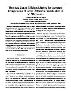
cnt_interface_fsm
receive_data_from_int transmit_data
Figure 7: Host Interface call graph
3.2 Results We find that our methods provide an efficient method to support calls in ASTI, allowing the developer to trade off speed for code size. The inlining of phase 1 is surprisingly effective, due to small procedure bodies. The grouping and cloning of phase 2 are also effective, significantly cutting padding cycles with marginal amounts of code expansion.
3.2.1 Phase 1
shutdown_fan handle_fan set_fan_speed
handle_error enqueue
handle_event
modulo_increment
send_acknowledgement handle_message
handle_adc change_power_mode handle_power
handle_ioport
get_bit_value write_data_register
handle_pwm read_data_register
write_bit_value
get_port_and_bit
Figure 9 presents the result of inlining the three applications. The amount of inlining increases going to the right on the graph. The inlining of Phase 1 was extremely effective for the benchmarks examined due to their small sizes, specifically the procedures are short, few and not deeply nested. Prologs and epilogs are large compared to the procedure bodies, so extensive inlining can be performed without increasing code size significantly. Our inlining approach did not take into account the impact of removing the prologs and epilogs and hence overestimated the cost of inlining. We expect that larger applications with more and longer procedures with deeper call graphs will not be as amenable to inlining. Keeping this in mind, and in order to examine the impact of Phase 2’s clustering, we choose code which has a moderate amount of inlining (105% expansion limit) as the input code for the next phase.
configure_bit enable_pwm disable_pwm
Figure 8: Smart Node call graph detail. Main also calls three other functions of much less complexity than handle message.
3.2.2 Phase 2 Figure 11 presents the impact of applying the cloning of Phase 2 to the Smart Node application with a clone ratio of 0.5. Padding cycles needed fall significantly, leading to improved performance. Note that this is a static measure of padding cycles, rather than dynamic; later in this analysis we examine the dynamic performance. The impact of cloning is emphasized at large values of TSegmentIdle , where the variance in Φ values is larger. Figure 12 shows how Phase 2 reduces the total number of padding cycles needed
Impact of Inlining
PID Controller Static Padding Cycles vs. Clone Ratio 1200
Figure 11: Phase 2 reduces static padding cycles needed for Smart Node. Impact rises with increasing TSegmentIdle .
Figure 12:
100
150
200 250 300 T Segment Idle
350
400
Static padding cycle reduction for all three benchmarks.
Normalized Code Size
2.2
PID Smart Node Host Interface
2 1.8 1.6 1.4
0.2 0.2 0.2 0.1 0.1
1.2 1 0
0.1 Clone Ratio=0
0.2 0.4 0.6 0.8 Normalized Static Padding Cycles
1
Figure 13: Raising clone ratio CR cuts padding cycles but adds code size. TSegmentIdle = 50 cycles
Static Padding Cycles vs. Code Size at TSegmentIdle = 400 cycles
Normalized Code Size
2.2
PID Smart Node Host Interface
2 1.8 1.6 1.4 0.2 0.2 0.1
1.2 1 0
0.1 0.2 0.1 Clone Ratio=0
0.2 0.4 0.6 0.8 Normalized Static Padding Cycles
1
Figure 14: With TSegmentIdle = 400 cycles, a small CR is more effective at reducing cycles.
Speed-up Relative to Non-Cloned Version
Static Padding Cycles vs. Code Size at TSegmentIdle = 50 cycles
Dynamic Speed-Up 1.7
PID Controller Host Interface Smart Node
1.6 1.5 1.4 1.3 1.2 1.1 1 0.9 50
100
150
200 250 TSegmentIdle
300
350
400
Figure 15: Speed-up of secondary thread varies with TSegmentIdle
the Smart Node requires a higher clone ratio to acheive similar reduction in padding cycles. This is due in part to the larger call graph size, as well as the distribution of Φ for the procedures. Finally, Figure 15 shows the speed-up of applying Phase 2 versus not applying it, while holding the amount of inlining constant. The speed-up is based on dynamic instruction count, through the body of each secondary thread’s cyclic executive loop. The CR is 0.5. Figure 15 shows speedups for all applications, which rise as TSegmentIdle grows, as expected. Smart Node and Host Interface have large speed-ups because the many of the padding cycles eliminated are in a frequently executed loops, magnifying the performance impact of cloning. PID Controller speedup is lower because only two calls appear in loops, reducing the penalty of padding. Furthermore, the body of the PID loop is long due to a lengthy fixed-point multiply procedure (recall the processor used lacks a hardware multiply, though more recent devices in the ISA do).
4. RELATED WORK for the three applications, with a clone ratio CR 0.5. The cycles needed fall to 0.27 to 0.05 of the original values. Figure 10 shows how padding cycles in the PID controller depend upon both clone ratio CR and TSegmentIdle . The other benchmarks have similar characteristics. As before, the impact is highest with large values of TSegmentIdle . Now we see that moderately small values of CR can significantly cut the padding cycles. Recall that CR is the ratio of clones to call sites. A CR of 1 indicates a clone is made for each call site and is equivalent to complete inlining. A CR of 0.2 indicates that five calls are clustered together for each clone. For the applications examined, a CR of 0.2 or 0.3 eliminates more than half of the padding cycles. Figures 13 and 14 examines how adjusting CR affects both padding cycles and total code size (relative to each application before phase 2), allowing an evaluation of the tradeoffs. The first figure has TSegmentIdle = 50 cycles while in the second it is 400.The first clones cut padding cycles the most. Again, a CR of 0.2 or 0.3 provides the majority of the padding cycle reduction with small code bloat. However,
Both compiler and design automation researchers have sought to reclaim idle time by interleaving code of multiple threads. Gupta [23] introduces interleaving of busy-idle profiles for reclaiming idle time but relies upon context switching. A fine-grain coroutine called software multithreading uses a compiler to insert coroutine call instructions immediately after long latency instructions, with the goal of increasing performance rather than providing increased concurrency [24]. Another technique called interval scheduling [25] enables static scheduling of operations with delay intervals, and guarantees that all fine grained max/min timing constraints for all combinations of actual delay values are met. This scheme avoids a run-time executive for scheduling. The design automation community has investigated compiling concurrent descriptions (e.g Esterel, Petri networks, SDL, Verilog, flow graphs, communicating sequential processes) of systems into software which runs efficiently on a generic processor despite context switching and scheduling overhead. Event-driven approaches require a dispatcher, al-
lowing dynamic execution at the expense of context-switching overhead. VULCAN [26] uses either a coroutine call or a large switch statement to perform the switching. Compiling Esterel to C requires generating context-switching code [27], as does compiling code for event-driven Verilog simulation [28]. This overhead has been reduced with quasi-static or compile-time scheduling [29–35], in which a model (e.g. Petri net) of a concurrent system’s specification is converted into a set of concurrent tasks, which in turn are dynamically scheduled (e.g. by a real-time operating system). For example, Picasso [33] provides a theoretic approach which begins with Petri nets and converts them to control-flow graph segments which follow Petri net firing rules. These fragments are generated in C and then compiled for the target machine. Ptolemy [31] uses quasi-static scheduling of dataflow graphs for multiprocessors. Lin [33] converts C-like code into Petri nets, then joining concurrent processes and extracting acyclic fragments to produce control-flow graph fragments in C, which can then be compiled and optimized. Procedure inlining is a well-known optimization technique [36] which works by replacing a procedure call with the actual body of the procedure and trades off code size for execution speed. Inlining may lead to three kinds of benefits which reduce execution time [10]. Direct effects include as the reduction in the number of call and return operations leading to increase in execution speed. There may be indirect effects upon the cache and virtual memory. Whole program optimization opportunities are broadened by allowing the compiler to use data flow properties of the calling context to specialize the inlined body or optimize the caller due to data flow properties in the inlined procedure [37, 38]. Procedure cloning is an inter-procedural optimization technique that works by creating specialized copies of a procedure. Procedures impose a barrier on the compiler’s potential regions of optimization; procedure cloning can expose larger regions. Cloning can implement multiple versions of each procedure, each tailored to suit some particular data flow or control flow path. It can be used as an alternative to inlining in this context, as there can be comparatively less code expansion with cloning. Procedure cloning has been applied [39] to the matrix300 program from release one of the SPEC benchmarks to reduce the amount of inlining needed before an optimization could be applied. Selective specialization [40] corresponds to using procedure cloning to reduce dynamic dispatch overhead in object-oriented languages. Procedure cloning has also been applied along with STI to create clones that have procedure level parallelism converted to instruction level parallelism [41].
5.
CONCLUSIONS AND FUTURE WORK
We present methods for efficiently supporting procedure calls in ASTI. Procedure calls are inlined and then clustered together according to similar timing characteristics. Code size and execution time can be traded off by adjusting the clone ratio. Adding procedure call support greatly increases the usefulness and applicability of ASTI. The techniques presented provide an algorithmic basis for trading off code size and processor efficiency. Clustering procedure calls results in significant savings in the amount of wasteful padding code that is required. These savings appear in the dynamic execution of the secondary thread, thus allowing more secondary work to be performed as compared to the approach which
does not use cloning. This is highly desirable as it will allow system designers to avoid raising clock speeds to improve the real-time performance of the secondary threads. These methods allow code writers to be freed from details of the later STI phase. The methods presented can be generalized by relaxing some assumptions made. The optimal inlining algorithm presented takes an all or none approach towards inlining a procedure - i.e. either all calls are inlined or none are. This can be relaxed to allow the algorithm to distinguish and choose between individual incoming calls of a procedure based on some other guiding criteria, like dynamic call frequency information, nesting under loops etc. This will lead to better code as a result of traditional inlining benefits. As a bonus to applying phase one to the secondary threads, a Partial Redundancy Elimination (PRE) phase at the end of phase one allows us to recover the traditional optimization potential benefit of inlining. Currently, due to the interdependence of call sites on each other due to vertical nesting in the call graph and occurrence in the control flow (dependence), timing information for call sites cannot be holistically determined. Our technique requires that procedures get padded to the multiple of a cocall which allows us to assume durations of procedures even before they are fully transformed. Padding to a multiple of a cocall represents a step in the backward direction and finding techniques to work around this will produce code that has improved real-time performance. Such a solution, though, requires an approach which looks at call sites one by one in the control dependence order, rather than holistically as done in this research.
6. REFERENCES
[1] “CAN specification version 2.0,” Robert Bosch GmbH, 1991. [Online]. Available: http://www.motsps.com/csic/techdata/refman/can2spec.pdf [2] AVR304 Half Duplex Interrupt Driven Software UART, Atmel Corporation, Aug 1997. [3] “Application note: Software lin slave,” Atmel Corporation, Feb. 2000. [4] AVR320 Software SPI Master, Atmel Corporation, May 2002. [5] AVR410 RC5 IR Remote Control Receiver, Atmel Corporation, May 2002. [6] A. G. Dean and R. R. Grzybowski, “A high-temperature embedded network interface using software thread integration,” in Second Workshop on Compiler and Architectural Support for Embedded Systems, Washington, DC, October 1999. [7] A. G. Dean, “Software thread integration for hardware to software migration,” Ph.D. dissertation, Carnegie Mellon University, February 2000. [8] N. J. Kumar, S. Shivshankar, and A. G. Dean, “Asynchronous software thread integration for efficient software implementations of embedded communication protocol controllers,” in Proceedings of the 2004 ACM SIGPLAN/SIGBED Conference on Languages, Compilers and Tools for Embedded Systems. ACM Press, June 2004. [Online]. Available: http://www.cesr.ncsu.edu/agdean/TechReports/p55kumar.pdf [9] M. E. Conway, “Design of a separable
[10]
[11]
[12]
[13]
[14]
[15]
[16]
[17] [18] [19]
[20] [21] [22] [23]
[24]
[25]
transition-diagram compiler,” Communications of the ACM, vol. 6, no. 7, pp. 396–408, 1963. M. Arnold, S. J. Fink, V. Sarkar, and P. F. Sweeney, “A comparative study of static and profile-based heuristics for inlining,” in ACM SIGPLAN Workshop on Dynamic and Adaptive Compilation and Optimization (DYNAMO’00). ACM, Jan. 2000, pp. 52–64. R. Leupers and P. Marwedel, “Function inlining under code size constraints for embedded processors,” in ICCAD, 1999, pp. 253–256. [Online]. Available: citeseer.ist.psu.edu/leupers99function.html V. Asokan, “Relaxing control flow constraints in asti,” Master’s thesis, North Carolina State University, Jul 2003. B. Welch, S. Kanaujia, A. Seetharam, D. Thirumalai, and A. G. Dean, “Extending sti for demanding hard-real-time systems,” in Proceedings of the International Conference on Compilers, Architectures and Synthesis for Embedded Systems. ACM Press, November 2003, pp. 41–50. P. Ganesan and A. G. Dean, “Enhancing the avrx kernel with efficient secure communication using software thread integration,” in Proceedings of the 10th IEEE Real-Time and Embedded Technology Applications Symposium. IEEE Press, May 2004. A. G. Dean, “Compiling for concurrency: Planning and performing software thread integration,” in Proceedings of the 23rd IEEE Real-Time Systems Symposium, Austin, TX, Dec 2002. Atmega 128: 8-Bit AVR Microcontroller with 128K Bytes In-System Programmable Flash, Atmel Corporation. [Online]. Available: http://www.atmel.com/dyn/resources/prod documents/doc2467.pdf SAE J1850 Class B data communication network interface, Society of Automotive Engineers, 1992. avr-gcc 3.2. [Online]. Available: http://www.avrfreaks.net/AVRGCC/index.php P82C150 CAN Serial Linked I/O Device (SLIO) with Digital and Analog Port Functions Data Sheet, Philips Semiconductors, JUn 1996. MCP2502X/5X CAN I/O Expander Family Data Sheet, Microchip Technology, Inc., Aug 2000. MIC74 2-Wire Serial I/O Expander and Fan Controller, Micrel, Inc., Aug 2000. PCF8574 Remote 8-bit I/O Expander for I2C-bus, Philips Semiconductors, Nov 2002. R. Gupta and M. Spezialetti, “Busy-idle profiles and compact task graphs compile-time support for interleaved and overlapped scheduling of real-time tasks,” in 15th IEEE Real Time Systems Symposium, 1994. C. J. Beckmann, “Hardware and Software for Functional and Fine Grain Parallelism,” Ph.D. dissertation, North Carolina State University, April 1993. [Online]. Available: citeseer.nj.nec.com/beckmann93hardware.html P. Chou and G. Borriello, “Interval scheduling: Fine grained code scheduling for embedded systems,” in
[26]
[27]
[28]
[29]
[30]
[31]
[32]
[33]
[34]
[35]
[36] [37]
[38]
[39]
Proceedings of the Design Automation Conference, June 1995, pp. 462–467. R. K. Gupta and G. De Micheli, “A co-synthesis approach to embedded system design automation,” Design Automation for Embedded Systems, vol. 1, no. 1-2, pp. 69–120, 1996. S. A. Edwards, “Compiling esterel into sequential code,” in Design Automation Conference, 2000, pp. 322–327. [Online]. Available: citeseer.nj.nec.com/edwards00compiling.html R. S. French, M. S. Lam, J. R. Levitt, and K. Olukotun, “A general method for compiling event-driven simulations,” in Design Automation Conference, 1995, pp. 151–156. [Online]. Available: citeseer.nj.nec.com/french95general.html E. A. Lee, “Recurrences, iteration, and conditionals in statically scheduled block diagram languages,” in VLSI Signal Processing III, R. W. Brodersen and H. S. Moscovitz, Eds. IEEE Press, 1988, pp. 330–340. C.Loeffler, A.Lightenberg, H.Bheda, and G. Moschytz, “Hierarchical scheduling systems for parallel architectures,” in Proceedings of Euco, September 1988. S. Ha and E. Lee, “Compile-time scheduling of dynamic constructs in dataflow program graphs,” 1997. [Online]. Available: citeseer.ist.psu.edu/ha97compiletime.html M. Sgroi, L. Lavagno, Y. Watanabe, and A. L. Sangiovanni-Vincentelli, “Quasi-static scheduling of embedded software using equal conflict nets,” in ICATPN, 1999, pp. 208–227. [Online]. Available: citeseer.nj.nec.com/sgroi95quasistatic.html B. Lin, “Efficient compilation of process-based concurrent programs without run-time scheduling,” in Proceedings of the conference on Design, automation and test in Europe. IEEE Computer Society, 1998, pp. 211–217. E. A. Lee and D. G. Messerschmitt, “Static scheduling of synchronous data flow graphs for digital signal processing,” IEEE Transactions on Computers, January 1987. J. Cortadella, A. Kondratyev, L. Lavagno, C. Passerone, and Y. Watanabe, “Quasi-static scheduling of independent tasks for reactive systems,” Design Automation Conference, June 2000. [Online]. Available: citeseer.nj.nec.com/541753.html F. Allen and J. Cocke, A Catalogue of Optimizing Transformations, P. Hall, Ed. Prentice Hall, 1972. S. Richardson and M. Ganapathi, “Code optimization across procedures,” Computer, vol. 22, no. 2, pp. 42–50, 1989. P. P. Chang, S. A. Mahlke, W. Y. Chen, and W. mei W. Hwu, “Profile-guided automatic inline expansion for c programs,” Software - Practice and Experience, vol. 22, no. 5, pp. 349–369, 1992. [Online]. Available: citeseer.ist.psu.edu/chang92profileguided.html K. D. Cooper, M. W. Hall, and K. Kennedy, “A methodology for procedure cloning,” Computer Languages, vol. 19, no. 2, pp. 105–117, 1993. [Online]. Available:
citeseer.ist.psu.edu/cooper93methodology.html [40] J. Dean, C. Chambers, and D. Grove, “Selective specialization for object-oriented languages,” in SIGPLAN Conference on Programming Language Design and Implementation, 1995, pp. 93–102. [Online]. Available: citeseer.ist.psu.edu/dean95selective.html [41] W. So and A. G. Dean, “Procedure cloning and integration for converting parallelism from coarse to fine grain,” in Proceedings of the Seventh Workshop on Interaction between Compilers and Computer Architectures, Feb 2003.