simulation between a specialist modeling tool called PSIM and the popular Matlab software ..... [9] Kjaer, S. B. (2012). Evaluation of the âhill climbingâ and the.
(IJACSA) International Journal of Advanced Computer Science and Applications, Vol. 7, No. 8, 2016
PSIM and MATLAB Co-Simulation of Photovoltaic System using ―P and O‖ and ―Incremental Conductance‖ MPPT ANAS EL FILALI
EL MEHDI LAADISSI
MALIKA ZAZI
Laboratory LM2PI, ENSET, Mohamed V University Rabat, Morocco
Laboratory LM2PI, ENSET, Mohamed V University Rabat, Morocco
Laboratory LM2PI, ENSET, Mohamed V University Rabat, Morocco
Abstract—The photovoltaic (PV) generator shows a nonlinear current-voltage (I-V) characteristic that its maximum power point (MPP) differs with irradiance and temperature. by employing simple maximum power point tracking algorithms, we can track this MPP and increase the efficiency of our photovoltaic system. Two methods for the maximum power point tracking (MPPT) of a photovoltaic system under variable temperature and insolation conditions are discussed in this work: Incremental Conductance compared to conventional tracking algorithm (P&O). In this paper, a new modeling solution is presented, using cosimulation between a specialist modeling tool called PSIM and the popular Matlab software using simcoupler module. Cosimulation is carried out by implementing the MPPT command circuits in PSIM and PV panel, boost DC-DC converter and battery in MATLAB/Simulink. Keywords—Photovoltaic; Boost; PWM; MPPT; P and O; Incremental Conductance; co-simulation
I.
INTRODUCTION
Photovoltaic power generation is nonpolluting, widedistribution and promising renewable energy. But there are many problems to be solved in the development process, and the energy efficiency is one of the key points. PV panel is a nonlinear source that converts visible light into direct current (DC), it is influenced by irradiation and temperature in its operation. The PV panel characteristic presents an optimal operation point called the maximum power point (MPP) that allows the panel to generate maximum power. Maximum power point tracking (MPPT) is the process of finding this point and keeping the operation there.]
characterized by a friendly simulation environment and powerful waveform processing. The rest of the paper is sorted out as follows: Section 2 presents a description of modeling the PV panel and covers theory of boost dc–dc converter of the PV system. Section 3 discuss on two MPPT algorithms P&O and InC in term of their structures and improvements. Simulation work including the results are discussed in Section 4. Finally, a simple conclusion is given in Section 5. II.
MODELING OF PV SYSTEM USING SIMULINK
A photovoltaic cell that absorbs solar energy and converts it into electricity, is basically a photoactive semiconductor PN junction diode. To increase the power obtained by the PV cell, we interconnect several PV cells, so that we get a PV panel. Different configurations can be used to model PV cell such as single diode model, two diode model [1], and 𝑅𝑠 -𝑅𝑝 model. the single diode configuration of PV module has been selected for this work due to degree of precision and simplicity, and the majority of previous works used single diode model [2]. A. Mathematical Equations Related to PV Modeling The basic solar cell equation is given by : (1) Where Id is the diode internal diffusion current which is defined by: )
((
)
(2)
There are different techniques used to track the maximum power point: Constant Voltage (CV) method, Constant Current (CC) method Perturb & Observe (P&O), Incremental Conductance (InC) etc. In this paper, performances of two most preferably used MPPT algorithms are compared: Perturb & observe and Incremental Conductance. Co-simulation tool is a very important tendency in electronic simulation, that allows to rely on the merits of two powerful environments in complementary way to improve the efficiency of a stand-alone photovoltaic system: Simulink as a powerful environment for system modeling and simulation and PSIM as a widely used software in many areas, and it is
Fig. 1. The equivalent circuit of PV cell
The I0 in the equation represents the dark saturation current or diode saturation current: (
)
(3)
72 | P a g e www.ijacsa.thesai.org
(IJACSA) International Journal of Advanced Computer Science and Applications, Vol. 7, No. 8, 2016
B. Modeling the PV Panel specifications of PV panel, made by Green light energy company, are presented in Table 1. TABLE I.
PV PANEL SPECIFICATIONS
Parameters Open Circuit Voltage (Voc) Short Circuit Current (Isc) Voltage at Pmax (Vmpp) Current at Pmax (Impp) Maximum Power (Pmpp) Number of Cell
Values 21.67 Volt 3.14 Amp 17.47 Volt 2.86 Amp 50 Watt 36
(b)
Based on mathematical equations related to PV modeling, a complete Simulink block diagram of PV panel is demonstrated in Fig 2.
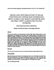
Fig. 3. (a) P-V characteristic of a PV panel (b) I-V characteristic of a PV panel for changed temperature
To test the validity of the PV model, we must have nonlinear characteristics. The figures below present the PV panel characteristics under changing climatic conditions. Fig 3 shows the variation in the characteristics at various temperature when temperature shifts from 0°C to 75°C and the irradiance is kept steady at 1000w/m², Then the temperature is kept constant at 25˚C while irradiance values varies from 400w/m² to 1000w/m². The variation in characteristics of the chose PV panel are presented in Fig 4.
(a)
(b) Fig. 4. (a) P-V characteristic of a PV panel (b) I-V characteristic of a PV panel for changed irradiance
Fig. 2. simulation model of PV panel
C. DC-DC Boost Converter DC-DC converters are employed for the transmission of the power of PV panel to battery side guaranteeing that maximum power has been transmitted which make use of MPPT [3]. The regulation is typically accomplished by pulse width modulation (PWM) that attacks the switching device which can be Bipolar power transistor or MOSFET; it depends on switching speed, voltage and current. The used battery has a nominal voltage of 24V, thus we use Boost dc-dc converter to increase dc voltage. Fig 5 shows the structure of boost converter in the PV system.
(a)
73 | P a g e www.ijacsa.thesai.org
(IJACSA) International Journal of Advanced Computer Science and Applications, Vol. 7, No. 8, 2016
Fig. 5. Basic circuit of the boost converter
The main role of the MPPT is to regulate the duty cycle of the boost converter to achieve maximum power. III.
MAXIMUM POWER POINT TRACKING ALGORITHM
A. Perturb and Observe Method P&O method is commonly used in PV systems. Based on the P-V characteristic, when PV power and voltage are expanding, a perturbation will add a step size ΔD with the duty cycle D, so as to create next cycle of perturbation and to drive the operating point moving toward the MPP. On the off chance that the PV power drops and PV voltage rises, the algorithm will work in the opposite way, until the algorithm reaches the MPP. This algorithm is not appropriate in high variation of the solar irradiation. The voltage oscillates around the maximum power point (MPP) and never reaches a precise value. The biggest advantage of P&O method is the easy implementation and simple to code it using cheap digital devices besides ensuring high robustness. However, this method presents oscillations around the MPP and it suffers when subjected to rapid irradiation change. [4] [5] [6] [7] [8].
Fig. 7. model of P&O MPPT in PSIM
B. Incremental conductance method This algorithm perturbs the voltage in one direction. If the sign of the derivative of the power dP/dV is positive, the algorithm will increase the voltage; else, it will decrease the voltage [9]. InC method is concluded from the differentiation of power with respect to voltage, due to this fact that this value in maximum power point is equal to zero. (
)
(4) (5)
Fig 6 and Fig 7 present the flowchart and the main circuit for P&O algorithm developed in PSIM environment
(6) Besides,
is called instantaneous conductance and
is incremental conductance, the place where these two values are equal the MPP will be there. Figures below show the flowchart of Incremental Conductance algorithm (Fig 8) and the mains circuit developed in PSIM environment (Fig 9)
Fig. 6. flowchart of P&O algorithm
74 | P a g e www.ijacsa.thesai.org
(IJACSA) International Journal of Advanced Computer Science and Applications, Vol. 7, No. 8, 2016
Fig. 10. Simcoupler block
Fig. 11. Model of PV System
Fig. 8. flowchart of Incremental Conductance algorithm
To generate pulse for controlled switch Mosfet of DC/DC boost converter, the output of PI controller is compared with carrier wave (Fig 7 and Fig 9) Simulink Model of PV System with MPPT that is used for simulations is depicted in Fig 11 The figures below present the variation of the power of the module with P&O and InC controllers in standard atmospheric conditions (1000W/m2, 25°C) using waveforms provided by SIMULINK and PSIM software.
Fig. 9. model of InC MPPT in PSIM
IV.
SIMULATION RESULTS
In this paper, an additional module to the PSIM software called Simcoupler, will be used, permitting for co-simulation between PSIM and SIMULINK. This module is easy to use and gives a quick simulation and waveform display in both PSIM and SIMULINK as shown in Fig 12 and Fig14.
(a)
To achieve this co-simulation, there are three modules as shown in Fig10. In PSIM, SLINK_IN module gets signal from SIMULINK and SLINK_OUT yield signal to SIMULINK. In SIMULINK, SimCoupler model block, interconnects with other part through input and output port. So that we can use the capability of two powerful softwares in complementary way. PI controller is used to eliminate the steady state error obtained as a result of comparison between the PV panel voltage and the varied voltage value. a limiter placed at the output of PI controller to avoid over saturation.
(b) Fig. 12. Performances of P&O and InC under standard atmospheric conditions (a) Simulink (b) PSIM
75 | P a g e www.ijacsa.thesai.org
(IJACSA) International Journal of Advanced Computer Science and Applications, Vol. 7, No. 8, 2016
MPP‘s line which causes waste of power while in the InC there is no such oscillations. Finally, despite of the general better performances of the InC algorithm presented in this paper, the simplicity of the P&O MPPT makes it largely used according to the facility to implement in most applications. V.
CONCLUSION
The simulation results demonstrate that the P&O and the Incremental Conductance MPPTs reach the expected MPP. Fig. 13. Step variation of irradiance
To evaluate and compare the performances of the P&O and InC MPPT algorithms, we did a simulation test in which the PV panel is exposed to a variation in irradiance as shown in Fig 13. The first level is set at G = 1000 w/m². At t = 0.05 sec, the irradiance is rapidly stepped down to G = 400 w/m², and then it is stepped up to 800 w/m² at t=0.1 sec. The temperature is kept constant at 25˚C all along diverse irradiance levels. The output power of the PV panel using the two algorithms is presented inn Fig 14.
(a)
(b) Fig. 14. Performances of P&O and InC under a rapid change in climatic conditions (a) Simulink (b) PSIM
By analyzing the figure, we can conclude that the InC starts to track the MPP little more quickly than P&O. The zoomed in window shows that P&O oscillates all over the
P&O and InC algorithms are both concluded from the derivative of power with voltage, however, results show some differences in the tracking performances of the two algorithms under both stagnant and variable conditions. It has observed that the Incremental Conductance reaches at the MPP little faster than P&O in all cases and shows better performance for fast irradiance changes and a better steadiness when the MPP is attained. It has observed that P&O oscillates all over the MPP‘s line which causes waste of power while in the InC there is no such oscillations. REFERENCES Ishaque, K., Salam, Z., Amjad, M., & Mekhilef, S. (2012). An improved particle swarm optimization (PSO)–based MPPT for PV with reduced steady-state oscillation. IEEE transactions on Power Electronics, 27(8), 3627-3638.], [2] Huan-Liang Tsai, Ci-Siang Tu, and Yi-Jie Su ―Development of Generalized Photovoltaic Model Using MATLAB/SIMULINK‖ Proceedings of the World Congress on Engineering and Computer Science 2008 WCECS 2008, October 22 - 24, 2008, San Francisco, USA [3] Bennett, T., Zilouchian, A., Messenger, R.: ‗Photovoltaic model and converter topology considerations for MPPT purposes‘, Sol. Energy, 2012, 86, pp. 2029–2040. [4] Sera, D.; Kerekes, T.; Teodorescu, R.; Blaabjerg, F. Improved MPPT Algorithms for Rapidly Changing Environmental Conditions. In Proceedings of Power Electronics and Motion Control, Portoroz, Slovenia, 30 August–1 September 2006; pp. 1614–1619 [5] Katherine A. Kim and Philip T. Krein, ―Photovoltaic Converter Module Configurations for Maximum Power Point Operation‖, University of Illinois Urbana-Champaign Urbana, IL 61801 USA. [6] Liu X., Lopes L.A.C.: ―An improved perturbation and observation maximum power point tracking algorithm for PV panels‖ Power Electronics Specialists Conference, 2004. PESC 04. 2004 IEEE 35th Annual Volume 3, 20-25 June 2004 Pages: 2005 - 2010 Vol.3 [7] Femia N., Petrone G., Spagnuolo G., Vitelli M.: ―Optimizing sampling rate of P&O MPPT technique‖ Power Electronics Specialists Conference, 2004. PESC 04. 2004 IEEE 35th Annual Volume 3, 20-25 June 2004 Pages: 1945 - 1949 Vol.3 [8] Lian, K.L.; Jhang, J.H.; Tian, IS., "A Maximum Power Point Tracking Method Based on Perturb-andObserve Combined With Particle Swarm Optimization," Photovoltaics, IEEE Journal of, vol.4, no.2,pp.626,633, March 2014 [9] Kjaer, S. B. (2012). Evaluation of the ―hill climbing‖ and the ―incremental conductance‖ maximum power point trackers for photovoltaic power systems. Energy Conversion, IEEE Transactions on, 27(4), 922-929 [10] M. A. Elgendy, B. Zahawi, and David J. Atkinson, ―Assessment of the Incremental Conductance Maximum Power Point Tracking Algorithm‖, IEEE Trans, vol. 4, no. 1, jan 2013 [1]
76 | P a g e www.ijacsa.thesai.org