native simulation is limited only to the validation of OS and application SW. ... is to insert a function called delay() into both OS and application SW code. The.
Timed HW-SW Cosimulation Using Native Execution of OS and Application SW Iuliana Bacivarov
Sungjoo Yoo Ahmed A. Jerraya SLS Group, TIMA Laboratory 46, Avenue Felix Viallet, 38031 Grenoble, France {iuliana.bacivarov, sungjoo.yoo, ahmed.jerraya}@imag.fr
1. Introduction In SoC design, the software becomes more and more significant to meet short time-to-market constraints as well as to exploit its reprogrammability. Since most of SoC design cycle is spent in validation, designers need to have a fast validation of SW design to achieve a real reduction in design cycle. The SW validation needs also to be accurate in terms of SW timing and in the context of the entire system execution. In this paper, we present a cosimulation method that enables fast and accurate SW simulation by incorporating native OS simulation1 into timed HW-SW cosimulation.
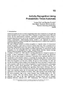
2. Related Work and Limitation in Conventional Native SW Execution SW validation tries to prove the right behavior of SW applications and/or operating systems (OSs). Conventionally, designers rely on the following SW validation methods: ISS2 based simulation, functional3 and native simulation. The ISS simulates the SW execution with instruction/cycle/phase accuracy. However, it has a significant disadvantage of slow simulation. The functional SW simulation focuses on the validation of the software application [1], not on the OS. In native simulation, SW applications and OSs are targeted on a simulation host, not on the target architecture. Note that native OSs are different from virtual OS models (e.g. Carbon Kernel [7], SoCOS [8]) in that native OSs are real OSs targeted on the simulation host and virtual OS models are OS simulation models, not real ones. An example of commercial native OS simulation model is VxSimTM of VxWorks Inc. [2]. Figure 1 shows an example of native simulation of a system with three processors. Each processor is modeled by native OS and SW execution (tasks in the figure). Communication between processors is modeled by IPC (inter-process communication) on the simulation host. For more details of native OS simulation model development, refer to [3]. The main advantage of native simulation is the simulation speed. However, conventional native simulation is limited only to the validation of OS and application SW. As shown in Figure 1, the HW part of system (e.g. processor i/f logics, communication network, shared memory, etc.) is not modeled accurately, but abstracted away by IPC. Even for the SW part, it performs a functional (untimed) simulation ignoring timing delay of execution of OS and application SW. Thus, conventional native simulation cannot distinguish between different architectural implementations (e.g. different processors, buses, memory, etc.) of the same OS and SW application.
Proc essor 1 Task 1
Task 2
Native OS
Proc essor 2
Proc essor 3
Task Task Task 3 4 5
Task Task 6 7
Native OS
Native OS
IPC (e.g. pipe, soc ket, etc .) Figure 1. An example of native simulation of OS and application SW. 1
. In this paper, we use native OS simulation and native OS execution, interchangeably. . Instruction Set Simulator 3 . Functional simulation means untimed simulation. 2
To achieve fast and accurate validation of the entire SoC design, native OS simulation needs to have timing simulation and it needs also to be incorporated with the HW simulation. There has been little research in such a timed cosimulation of native SW execution4 with HW simulation. In our work, we solve this problem by adding timing simulation functionality to native OS simulation and by enabling timed HW-SW cosimulation of native SW execution and HW simulation.
3. Proposed Method 3.1. Our Cosimulation Model Our objective is to simulate an RTL implementation as shown in Figure 2 (a). It consists of processor(s), HW IP(s), communication network, and processor/IP interfaces. On the processor(s), we have application SW tasks and OS(s). To obtain the cosimulation model of RTL implementation, we build a timed simulation model of SW part (as shown in Figure 2 (b)) using (1) a timed simulation model of OS and application SW and (2) a bus functional model (BFM). For the HW part, we can use fast HW simulation models (e.g. in SystemC) or conventional HDL models.
ARM 7 sim ulation m odel
HW IPs
ARM7 T1 T2 T3
T10
OS
T1
T2
H W IP s
T3
T im ed O S sim ulation m o del
T10
B FM
Processor I/F
HW I/F P roc. I/F
Communication Network
H W I/F
C om m un icatio n N etw o rk
Figure 2. (a) An RTL architecture and (b) its cosimulation model. - Timed OS simulation model Timed OS simulation model refers to the native OS simulation model annotated with timing delays. Delay annotation is to insert a function called delay() into both OS and application SW code. The function delay() has two functionalities: (1) advance of simulation time in the native execution of OS, in synchronization with HW simulation and (2) simulation of processor exceptions. Details of delay calculation and timed simulation with processor exception will be presented in Section 3.2. A native SW execution runs usually as a separate process (e.g. Unix process) on a simulation host. For access from/to native OS simulation models, IPC is used. For instance, for an access to processor peripherals, Unix shared memory can be used. For modeling processor interrupt, Unix signal can be used. Such an IPC interface depends on OS vendors. - BFM To achieve HW-SW cosimulation with native SW execution, we need to adapt native SW execution with HW simulation. To do that, we use a bus functional model (BFM). The BFM has two sides. One is facing the native OS simulation model (in our case, a UNIX process) and the other is a pin-level interface of the processor. Figure 3 shows an example of BFM for a native OS simulation model. In the
4
. In this paper, we call native execution of OS and application SW, in short, native SW execution.
figure, the native OS simulation model uses, as IPC, shared memory, signal, and semaphore for external access. The BFM transfers external access from the OS simulation model to HW simulation (in the figure, SystemC HW simulation). To do that, it polls on read/write access from the OS simulation model by polling on the IPC interface of OS simulation model (in the figure, Unix shared memory). If there is an access (e.g. read/write), it transforms the access into signal transitions on its processor pin interface (in SystemC). The BFM transfers also a processor interrupt to the OS simulation model. In this case, if the interrupt arrives on processor interrupt pin(s), the BFM sends a signal (e.g. Unix signal) to the OS simulation model (i.e. to a Unix process).
OS Simulation Model
_shm IPC
Semaphores
Signals
Ctrl
Info
-> To Unix
Ctrl + Info Processing BFM
Processor Signals Processing -> To SystemC
Addr
IT DataOut
DataIn
Status
SystemC Signals
Hardware Interface
Figure 3. Bus Functional Model for a native OS simulation model.
3.2. Timed Native SW execution Delay annotation has been widely used to account for timing behavior of simulation of SW part [4][5]. In conventional methods of delay annotation, during simulation, annotated delays are accumulated and timing synchronization between SW and HW simulation is done using the accumulated delays. In our work, to enable timed OS simulation, we add to the conventional techniques, two new techniques (1) various granularity support in timing synchronization and (2) simulation of processor exceptions.
3.2.1 Delay Calculation and Annotation For delay annotation into a real OS source code (in C), we first obtain the assembly code of the real OS code by compiling it on the target processor. Then, we find the correspondence between OS source code and the compiled assembly code. To do that, we use compiler-specific information (e.g. in the gnu compile case, using objdump) of code correspondence. Figure 4 shows an example of delay annotation. After compiling the source code of OS and application SW (in C, in the figure), we find a correspondence between the source code and assembly code. For each source code line, we can find a set of assembly instructions. Then, we calculate the execution time of each assembly instruction in terms of number of processor clock cycles by consulting the data sheet of the target processor. At the last step of delay annotation, we insert, into the source code, the function delay() that contains the calculated values as one of its arguments.
C Code Example
:
... i=4; i++; j=i*8; i=j*j; j-=5; ...
Target Compiler (for ARM7: armcc)
ASM Code Example ...
MOV MOV ADD MOV MOV MOV MUL SUB MOV
a1,#4 v1,a1 a1,v1,#1 v1,a1 a1,v1,LSL #3 v2,a1 v1,v2,v2 a1,v2,#5 v2,a1 ...
Delay Calculation and Annotation
Annotated SystemC Code: i=4;
Delay([MOV, op1, op2], gr);
i++;
Delay([MOV, op1 ,op2], gr); Delay([ADD, op1, op2, op3], gr); Delay([MOV, op1 ,op2], gr);
j=i*8;
Delay([MOV, op1, op2, op3], gr);
i=j*j;
Delay([MOV, op1, op2], gr); Delay([MUL, op1, op2, op3], gr);
j-=5;
Delay([MUL, op1, op2, op3], gr); Delay([MOV, op1, op2], gr);
Figure 4. A simplified view on delay annotation. 3.2.2 Granularity of Timing Synchronization The function delay() synchronizes SW and HW simulation. For the synchronization, IPC is used to exchange timing information between native SW execution (e.g. a Unix process) and HW simulation (another Unix process). Thus, too frequent synchronization will cause synchronization overhead to dominate the whole simulation runtime. Reducing the number of synchronizations will resolve the problem, but it will cause more timing error in simulation. To solve this problem, we support multiple levels of granularity of timing synchronization. At the most accurate level, instruction-level timing synchronization can be adopted. We also support several other granularities: time period, source line-by-line, and function-by-function. Time period-based granularity enables the designer to set a minimum time period of timing synchronization. For instance, if 10 us is set to be the time period, then every 10 us, SW and HW simulation is synchronized. To the same annotated code, we can apply different types of timing granularity. Timing granularity is easily implemented in the function delay() that will be described in Section 3.2.3. 3.2.3 Simulation of Processor Exception in Synchronization between Native SW execution and HW Simulation In function delay(), processor exceptions (especially, hardware interrupt) needs to be simulated together with the advance of SW simulation time. Figure 5 shows a code section of function delay(). For explanation purpose, we assume that the native OS simulation model uses Unix shared memory for external access, that the BFM is written in SystemC, and that the timing granularity of synchronization is instruction level. In function delay(), SW simulation time elapses in function SW_wait() in line 9 of Figure 5. Function SW_wait() communicates with the BFM. Figure 6 (a) shows details of function SW_wait(). It sends the delay value to the BFM (line 3 in Figure 6 (a)) and waits on a response from the BFM (line 4). In the BFM, we have a counterpart function of SW_wait() as shown in Figure 6 (b). The counterpart function (BFM::SW_wait()) receives the delay value (line 3 in Figure 6 (b)). In line 4 of Figure 6 (b), the BFM waits on processor interrupt event for the time period of delay. In line 5, the BFM sends current HW simulation time and interrupt event status (interrupt or not) to the SW simulation.
1 void delay(– , int delay, int granularity) { 2 int last_time; 3 time2consume[cur_task] = delay: 4 5 switch (granularity) { 6 case ( instruction_level ) : 7 while( time2consume[cur_task] > 0 ) { 8 last_time = cur_SW_time; 9 interrupt = SW_wait(time2consume); 10 time_elapsed = cur_SW_time ⣵ last_time: 11 time2consume[cur_task] -= time_elapsed; 12 if( interrupt == true ) ISR(); 13 } 14 break; 15 case (time_period) : 16 – 17 case (line_by_line) : 18 – 19 } 20 }
Figure 5. Pseudo code of function delay In Figure 6 (a), function SW_wait() receives the current HW simulation time and interrupt event status in lines 5 and 6. When the function SW_wait() returns, in Figure 5, remaining delay value is calculated (line 11). Then, if there is an interrupt, the interrupt service routine (ISR) is simulated (line 12). When the ISR returns, if there remains still a time delay for the (preempted) SW task, function SW_wait() is called again (line 9). Note that even in the ISR execution, function delay() can be executed and that during the ISR execution, the OS scheduler can be called and another (preempted) task can be resumed. 1 // Timed native OS simulation function 2 int SW_wait(int time2consume) { 3 send time2consume to BFM via Unix shared memory. 4 wait on Unix shared memory write by the BFM 5 cur_SW_time = cur_HW_time; 6 if( interrupt arrives ) return true; 7 else return false; 8 } (a) Function SW_wait used in native OS simulation 1 // SystemC code 2 BFM::SW_wait() { 3 wait on Unix shared memory to receive time2consume. 4 wait(time2consume, proc_interrupt_event); 5 write cur_HW_time and interrupt info in Unix shared memory 6 } (b) Function SW_wait used in BFM in SystemC
Figure 6. Function SW_wait in native OS simulation and in BFM.
4. Experiments - System Examples In experiments, we use two system examples: McDrive and VDSL. The McDrive example consists of one ARM7 and three IPs, point-to-point interconnection as shown in Figure 7. The VDSL example consists of two ARM7 processors, one IP, and point-to-point interconnection between processors and IP.
Unix Simulation SystemC Simulation T1 + time
T2 + time
T3 + time
OS Unix + Time Annotations
OS
Client
TIR
Reset
BFM Hw Interface Communication Network Unix Environment
Figure 7 “ McDrive example. - Overall Simulation Environment We use native OS simulation models running on Unix and HW simulation in SystemC. Native OS simulation models automatically generated using an automatic OS generation tool with Unix as a target processor [6]. The native OS simulation model and SW application are annotated with delay by our delay annotation tool. For the McDrive example, when inserting function delay() for each assembly instruction, the annotated code of application SW (OS code) grows from 350 (~1,000) to 6,000 (~10,000) lines. - Native OS Simulation Model Interface and BFM
OS Simulation Model (UNIX process) Get()
DATA
P/GFlag
Delay(n)
It number n cycles
SIGIT
ADDR
ISR
Lock/Unlock SEMAPHORE
Put()
Shm
Unix IPC: Shared Memory, Semaphores, Signals
Figure 8 shows details of interface between the timed native OS simulation model and the BFM that we developed in SystemC for ARM7 processor. The communication between the timed native OS simulation model and the BFM is realized by Unix shared memory. For the communication, we have five fields on the shared memory: address, data, control flags, interrupt number, and SW execution delay.
Wait(n)
...
IRQ
DATAOut
DATAIn
ADDR
SystemC Signals
BFM (SystemC)
HW Simulation (SystemC threads)
Figure 8 “ Communication between timed native SW execution and BFM.
- Experiments Status and Plan Currently, we have finished the automatic annotation tool development and BFM design. By the conference (October), we will compare the simulation performance between ISS-based validation and the presented timed cosimulation. We will also investigate the effects of different granularities of timing synchronization on simulation performance and accuracy with the two system examples. Another future direction of our work is automatic generation of BFM for timed native OS simulation and applying the presented method to commercial native OS simulation models.
5. Summary Conventional native execution of OS and application SW cannot account for timed HW-SW cosimulation. In this paper, we present a method of timed HW-SW cosimulation between native SW execution and HW simulation. To build a timed native SW execution model, the execution delay information is automatically inserted into the code of OS and application SW. Timed native SW execution and HW simulation synchronize with each other using function delay() (in native SW execution) and the BFM (in HW simulation). The presented method enables timed simulation of processor interrupt during native SW execution. Moreover, to enable trade-off between simulation performance and accuracy, several granularities of timing synchronization are provided. We are working on applying the method to two real system examples to prove the effectiveness of the presented method in terms of simulation performance and accuracy.
References [1] James A. Rowson, ” Hardware/Software Co-Simulation„, Proc. DAC, 1994. [2] VxSim, Windriver Systems Inc. Available at http://www.windriver.com/products/html/ vxsim.html [3] S. M. Tan, et. al., ” Virtual Hardware for Operating System Development„, Technical rep., UIUC, Sep. 1995. Available at http://choices.cs.uiuc.edu/uChoices/Papers/uChoices/ vchoices/vchoices.pdf [4] M. Lajolo, M. Lazarescu, A. Sangiovanni-Vincentelli, ” A Compilation-based Software Estimation Scheme for Hardware/Software Co-simulation„, Proc. CODES, 1999. [5] Virtual Component Codesign, Cadence Design Systems Inc. Available at http://www.cadence. com/products/vcc.html [6] S. Yoo, G. Nicolescu, L. Gauthier and A. A. Jerraya, Automatic Generation of Fast Timed Simulation Models for OS in SoC Design, Proc. DATE, 2002. [7] Carbon Kernel, available at http://www.carbonkernel.org/ [8] D. Desmet, .et .al, ” Operating System Based Software Generation for Systems-on-Chip„, Proc. DAC, 2000.