Proceedings of 6th Thin Film Materials & Devices Meeting November 2-3, 2009, Kyoto, Japan http://www.tfmd.jp/
Pulse-Width Modulation with Current Uniformization using Reduced Pixel Circuit for TFT-OLEDs Daisuke Suzuki1, Masamichi Koike1, Shigeki Sawamura2, Masakazu Kato3 and Mutsumi Kimura1,4 1
Ryukoku University, Seta, Otsu, 520-2194, Japan,
[email protected] Nara Institute of Science and Technology, Takayama, Ikoma 630-0192, Japan 3 Osaka University, Yamadaoka, Suita 565-0871, Japan 4 Innovative Materials and Processing Research Center, Seta, Otsu 520-2194, Japan 2
Keywords: Pulse-Width Modulation, Current Uniformization, Pixel Circuit, TFT-OLED
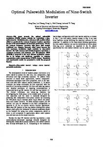
Abstract. We have proposed a novel driving concept for TFT-OLEDs, pulse-width modulation with current uniformization. This driving method can simultaneously achieve precise grayscale and exceedingly improve luminance uniformity. Lately, we succeeded to reduce the number of TFTs in a pixel circuit from nine to seven. Especially in this paper, its working and tolerance against characteristic deviations of TFTs and OLEDs are confirmed using circuit simulation. Introduction TFT-OLEDs have been highlighted for a next generation of flat-panel displays [1-2]. One of the most critical issues for TFT-OLEDs is luminance uniformity between neighboring pixels. In order to improve the luminance uniformity, many kinds of driving method were proposed [3-11]. Formerly, we and another group presented pulse-width modulations with self-biased inverter [6-7]. These driving methods can compensate characteristic deviation of TFTs. However, they cannot compensate characteristic deviation of OLEDs. On the other hand, recently, we presented a time-ratio grayscale with current uniformization [11]. This driving method can compensate characteristic deviations of both TFTs and OLEDs. However, it needs high-speed scanning for high-resolution and many-grayscale displays. We have proposed a novel driving concept for TFT-OLEDs, pulse-width modulation with current uniformization [12]. This driving method can simultaneously achieve precise grayscale and exceedingly improve luminance uniformity. Lately, we succeeded to reduce the number of TFTs in a pixel circuit from nine to seven [13]. Especially in this paper, its working and tolerance against characteristic deviations of TFTs and OLEDs are confirmed using circuit simulation [14]. Pulse-width modulation with current uniformization This driving method can simultaneously achieve precise grayscale using the pulse-width modulation and exceedingly improve luminance uniformity using the current uniformization. The pixel circuit consists of the Pwm-part, pulse-width modulation part, and Cu-part, current uniformization part, as shown in Fig. 1. Here, the reduced TFTs and buslines that exist in the
100228075-1
conventional pixel circuit of the pulse-width modulation with current uniformization are shown using the dotted lines. The working of the Pwm-part is explained as follows. First, during an addressing period, data-addressing operation is executed. Since Vin and Vout are connected, the voltage difference between Vdata and Vsb, Vth of the inverter, can be stored in the Csig. Next, during a light-emitting period, pulse-width-modulation operation is executed. Since a sweep wave is applied and coupled to Vin through the Csig, and the voltage difference between Vdata and Vsb is already stored in the Csig, the Pwm-TFT can be correctly turned on, and Woled, light-emitting time, can be exactly controlled. On the other hand, the working of the Cu-part is explained as follows. First, during a programming period, current-programming operation is executed. Since the Prg-TFT and Sup-TFT are turned on, the proper voltage for Itft=Isup can be stored in the Cst. Since Isup is enough to charge the Cst and whole pixel circuit, Vpx is settled, and Itft is asymptotical to Isup. Next, during a light-emitting period, current-reproduce operation is executed. Since Vgs of the Dr-TFT is already stored in the Cst, Itft is unchangedly kept, and Ioled can be roughly equal to
Vdd
Vemit
DrTFT Cu-part
Pwm-part
Vdd
Itft
Cst
Vscan
PrgTFT
Vcat
Inverter EmitTFT
Addressing and programming period
Vscan
Vpx
Data signal
Vsig
Vin
Vsig
Vout
PwmTFT
Csig
Vin
Pixel InvTFT
Ioled
Vinv
OLED
Isup Driver SbTFT Vscan
Vdata-Vsb
Vsb
Vout
Itft
Woled
Ioled
Light emitting
Vcat
(a) Pixel circuit Pwm-part Cu-part
Sweep wave
Vdata Vdata-Vsb
SupTFT
Light-emitting period
(b) Timing chart
Pulse-width modulation part Current uniformization part
TFT to connect input and output of self-biased inverter Sb-TFT Inv-TFT TFT to power inverter Csig Capacitor to store Vdata and Vsb Dr-TFT TFT to drive OLED with constant current Prg-TFT TFT to program proper voltage in Cst Sup-TFT TFT to supply constant current from Isup Pwm-TFT TFT to control light emitting time by pulse-width modulation Emit-TFT TFT to define light-emitting period Cst Capacitor to store Vgs of Dr-TFT
Vscan Vsig Vdata Vin Vout Vsb Vinv Vcat Vpx Vemit Isup Itft Ioled Woled
Scanning voltage Signal voltage Data voltage related to data signal Input voltage inputted to inverter Output voltage outputted from inverter Vth of inverter detected by self-biased inverter Voltage applied to Inv-TFT Cathode voltage Pixel voltage between Dr-TFT and OLED Voltage applied to Emit-TFT Current from constant current supply Current through Dr-TFT Current through OLED Light-emitting time
Fig. 1 Pulse-width modulation with current uniformization.
100228075-2
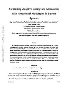
Isup. Since only one operating point is used in the current-programming operation, and it can coincide with the operating point in the current-reproduce operation, the current variation due to the shift of the operating points does not occur. Recently, we succeeded to reduce the number of TFTs in a pixel circuit from nine to seven. First, the Inv-TFT to power off the inverter can be reduced because it does not matter whether the inverter is powered on or off when the pixel circuit is not selected during the addressing and programming period. Next, the Emit-TFT to define the light-emitting period can be also reduced because the same function is obtained when the cathode voltage is varied. As a result, we also reduce the number of buslines in an array panel from six to four. Simulation results We confirm the working of this driving method using circuit simulation as shown in Fig. 2. Here, typical characteristics and optimized designs are used, the addressing and programming period is 16 Ps per one scan line, the light-emitting period is 8 ms, and Vdata is 2.5 V by assuming that the pixel pitch is 200 Pm, the maximum luminance is 100 Cdm-2, the scan-line number is 500, and the halftone grayscale is displayed. An original TFT model is implemented in the circuit simulation [15] It is found in the simulated voltage and current waveforms shown in Fig. 2(b) that Woled can be exactly controlled, whose value of 3.94 ms is almost similar to the required value of 4 ms, and Ioled can be roughly equal to Isup, whose value of 0.998 PA is almost similar to the required value of 1 PA. We also confirm the tolerance against 'Vth of TFTs and OLEDs using circuit simulation as shown in Fig. 3. Here, the variations of Woled, Ioled and Loled, light-emitting brightness, whose
Pwm-part
p
2
2
S/A
n
2
2
0.75
n
2
2
0.75
C (pF) 0.1
Csig
Type
Cst
10
p n n n
W L LDD (Pm) (Pm) (Pm) 5 2 S/A 2 2 0.75 10 2 0.75 10 2 0.75
Light-emitting period
104 Vscan
5
Vin=Vout
53
4 Vemit
3
Vsig
0
Vin
02 Isup
-5
Cu-part
Dr-TFT Prg-TFT Sup-TFT Pwm-TFT
Addressing and programming period
Vsig
-51
Ioled=0.998uA
Isup
1
Woled=3.94ms
-10
-100
Itft
-15 0
8 t (us)
-15-1 16 0
0
Ioled
-1 2
4 t (ms)
6
C (pF) 2
(a) Design parameters
2
Vout
(uA)
Inverter -TFT Inverter -TFT Sb-TFT
W L LDD (Pm) (Pm) (Pm)
(V)
Type
(b) Voltage and current waveforms
Fig. 2 Working confirmation of the driving method using circuit simulation.
100228075-3
8
value is estimated by multiplying Woled by Ioled, are evaluated. It is found in Fig. 3(a) that the average value of Woled is almost similar to the required value and the variation of Woled is sufficiently small against 'Vth of TFTs. Moreover, the average value of Ioled is also almost similar to the required value, and the variations of Ioled is also sufficiently small except for 'Vth of TFTs is -0.5 V. Consequently, so is Loled. It is also found in Fig. 3(b) that the average value of Woled is almost similar to the required value and the variation of Woled is sufficiently small against 'Vth of OLEDs. Moreover, the average value of Ioled is also almost similar to the required value, and the variations of Ioled is also sufficiently small except for 'Vth of OLEDs is -1 V. Consequently, so is Loled. Since 'Vth of TFTs of -0.5 V and 'Vth of OLEDs of -1 V are considerably large values and those in mass-fabrication technologies is probably small, it is verified that the pulse-width modulation with current uniformization using reduced pixel circuit can simultaneously achieve precise grayscale and exceedingly improve luminance uniformity.
1.1
110
1
100
4
Loled (%)
4.1 Ioled (PA)
Woled (ms)
4.2
0.9
90
3.9 3.8
0.8 -0.5
0
0.5
80 -0.5
0
'Vth (V)
0.5
-0.5
0
'Vth (V)
Woled
0.5
'Vth (V)
Loled
Ioled (a) 'Vth of TFTs 1.1
110
1
100
4
Loled (%)
4.1 Ioled (PA)
Woled (ms)
4.2
0.9
90
3.9 3.8
0.8 -1
-0.5
0 'Vth (V)
Woled
0.5
1
80 -1
-0.5
0
0.5
'Vth (V)
Ioled
1
-1
-0.5
0 'Vth (V)
Loled
(b) 'Vth of OLEDs Fig. 3 Tolerance confirmation against characteristic deviations of TFTs and OLEDs.
100228075-4
0.5
1
Conclusion We have proposed a novel driving concept for TFT-OLEDs, pulse-width modulation with current uniformization. This driving method can simultaneously achieve precise grayscale and exceedingly improve luminance uniformity. Lately, we succeeded to reduce the number of TFTs in a pixel circuit from nine to seven. Especially in this paper, its working and tolerance against characteristic deviations of TFTs and OLEDs were confirmed using circuit simulation. We will confirm its working and tolerance against characteristic deviations of TFTs and OLEDs using actual pixel equivalent circuits in the near future. Acknowledgments The authors wish to thank Drs. Hiroyuki Hara, Satoshi Inoue, Hitoshi Fukushima, Tomoyuki Kamakura, Simon W. B. Tam, some members of Seiko Epson, Prof. Tatsuya Shimoda of Japan Advanced Institute of Science and Technology, Silvaco International, Silvaco Japan, Cadence Design Systems, Cadence Design Systems Japan, Dr. Yoshiki Katsuyama of Cybernet Systems, and Dr. Tsuneo Munakata of Jedat. This research is partially supported by a collaborative research with Seiko Epson Corporation, a research project of the Joint Research Center for Science and Technology of Ryukoku University, a grant for research facility equipment for private universities from the Ministry of Education, Culture, Sports, Science and Technology, and a grant for special research facilities from the Faculty of Science and Technology of Ryukoku University. References [1] M. Kimura, I. Yudasaka, S. Kanbe, H. Kobayashi, H. Kiguchi, S. Seki, S. Miyashita, T. Shimoda, T. Ozawa, K. Kitawada, T. Nakazawa, W. Miyazawa and H. Ohshima, IEEE Trans. Electron Devices 46, 2282 (1999). [2] M. Kimura, H. Maeda, Y. Matsueda, H. Kobayashi, S. Miyashita and T. Shimoda, J. SID 8, 93 (2000). [3] M. Kimura, Y. Matsueda, T. Ozawa and M. J. Quinn, Jpn. Patent Application, H10-69147 (1998) (in Japanese). [4] R. M. A. Dawson, Z. Shen, D. A. Furst, S. Connor, J. Hsu, M. G. Kane, R. G. Stewart, A. Ipri, C. N. King, P. J. Green, R. T. Flegal, S. Pearson, W. A. Barrow, E. Dickey, K. Ping, S. Robinson, C. W. Tang, S. V. Slyke, C. H. Chen, J. Shi, M. H. Lu, M. Moskewicz and J. C. Strum, SID '99, 438. [5] http://www.sony.co.jp/SonyInfo/News/Press/200102/01-007/ (in Japanese). [6] S. W. B. Tam, M. Kimura, R. Friend, T. Shimoda and P. Migliorato, IDW '02, 243. [7] H. Kageyama, H. Akimoto, T. Ouchi. N. Kasai, H. Awakura, N. Tokuda and T. Sato, SID ’03, 96. [8] R. M. A. Dawson, Z. Shen, D. A. Furst, S. Connor, J. Hsu, M. G. Kane, R. G. Stewart, A. Ipri, C. N. King, P. J. Green, R. T. Flegal, S. Pearson, W. A. Barrow, E. Dickey, K. Ping, S. Robinson, C. W. Tang, S. V. Slyke, C. H. Chen, J. Shi, M. H. Lu and J. C. Strum, IEDM '98, 875. [9] M. Ohta, H. Tsutsu, H. Takahara, I. Kobayashi, T. Uemura and Y. Takubo, SID '03, 108. [10] Y. Matsueda, D.-Y. Shin, K.-N. Kim, D.-H. Ryu, B.-Y. Chung, H.-K. Kim, H.-K. Chung and O.-K. Kwon, IDW '04, 263. [11] M. Kimura, Y. Hara, M. Kato, H. Hara, T. Okuyama, S. Inoue and Tatsuya Shimoda, Jpn.
100228075-5
J. Appl. Phys. 45, 4407 (2006). [12] M. Kimura, D. Suzuki, Y. Hara, S. Sawamura and M. Kato, SID '08, 1173 (2008). [13] D. Suzuki, M. Koike, S. Sawamura, M. Kato and M. Kimura, AM-FPD '09, 177. [14] D. Suzuki, M. Koike, S. Sawamura, M. Kato and M. Kimura, The 6th Thin Film Materials and Devices Meeting, 129 (2009) (in Japanese). [15] M. Kimura, S. Inoue and Tatsuya Shimoda, IEEE Trans. Computer-Aided Design of ICAS 21, 1101 (2002).
100228075-6