models for the architectural, conceptual and detailed design for ..... (e.g., PowerPoint, Visio) are still necessary. 5.2 Vendor ... Bay, Jamaica, October 2005.
Putting the “Engineering” into Software Engineering with Models Brian Berenbach, Sascha Konrad Siemens Corporate Research, Inc. {brian.berenbach, sascha.konrad}@siemens.com Abstract Models are frequently used for illustrations in software design documents. Commonly they are used to show static structure and less often, external dynamic behavior. However, in software engineering, the lack of conceptual models often inhibits creativity and understanding, which may in turn lead to incomplete or poor design. This paper describes our experience using models for the architectural, conceptual and detailed design for software systems, identifies perceived weaknesses in traditional approaches and makes recommendations for future modeling tools and techniques.
1. Introduction Each domain has its own standard for design or modeling. In civil and mechanical engineering blue prints are used, where a blueprint is defined as “a plan or technical drawing usually documenting an architecture or an engineering design” [1]. More generally, the term "blueprint" has come to be used to refer to any detailed plan. In electrical engineering there is the traditional circuit diagram. This has been augmented in electronics design with standards for circuit board design. In the software world it is recognized that working in the problem domain results in higher productivity and better quality products, than working at a low level [2], the question is, how to get there? One of the authors (Berenbach) was involved in the 1980s with the development of graphical languages for chemical process and power plant design. He had first hand exposure to the difference between a procedural and domain oriented language. One of the languages developed was the CETRANTM language.1 The CETRANTM language is an object-oriented language for the high-level, graphical design of control systems. A new hire was asked to do some heat exchanger software design and was left to his own devices. This effort required creating a FORTRAN software model of heat exchanger behavior. Two months later, he came back 1
CETRAN is a trademark of the ABB Corporation.
with the software. Apparently, no one had told the new hire about the CETRANTM language. The employee’s supervisor then redid the design using CETRAN in under two hours and the code was compiled directly from the CETRAN drawing. When creating designs for other domains, even when the output is software, it is possible and sometimes necessary to use a domain specific language. However, what happens when the design will be for a complex software system designed and implemented by software professionals (as opposed to non-software domain experts)? Researchers have taken steps towards improving the engineering process when using models. For example, the use of a UML 2.0-based metamodel has been explored for software process modeling [3]. Also, the use of UML for conceptual modeling has been reported [4]. Martin Fowler has stated: “The fundamental driver behind [graphical modeling languages] is that programming languages are not at a high enough level of abstraction to facilitate discussions about design” [5]. So we perceive three major problems with the use of models for software engineering: • Incorrect use of models by novices • Inadequate tooling • Insufficient training in engineering design These three problems are described in more detail below.
2. Common modeling mistakes In general, developers understand the benefits modeling can bring, but often make common mistakes when applying these techniques. Since the switch to UML is sometimes combined with the transition to object-oriented design techniques, modelers can make mistakes stemming from not fully understanding the concepts of object-oriented development. Some common mistakes have been documented by Malveau et.al. in the form of anti-patterns [6]. Similar to design
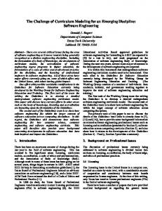
Figure 1 Conceptual Diagram in Mechanical Engineering patterns [7], an anti-pattern is a commonly reinvented solution to problems faced by developers when applying object-oriented development techniques. However, in contrast to design patterns, the anti-patterns negatively affect system design and potentially cause more problems than they solve. A sample object-oriented anti-pattern is the so-called Singletonitis; an overuse of the well-known Singleton design pattern [7]. Stewart identified 25 (and more) common mistakes done by developers in real-time software development [8]. One of the most severe mistakes he identifies is that documentation is written after the implementation, instead of before and during. Subsequently, we describe common mistakes that we identified in UML specifications obtained from customers.
2.1 Using the UML just for “pretty pictures” A common misconception is that a UML diagram is just a “pretty picture” of the software system to be developed. However, a UML diagram should provide a correct abstraction of parts of or the whole system (as done by the blueprint for the boiler shown in Figure 1).
If the diagram does not correctly reflect the system that will be realized, then the usefulness of the diagram is questionable. In the worst case, the diagram could convey incorrect information about the system to the reader. The level of abstraction between diagrams may also vary. For example, a use case diagram may be used to describe a contextual view of the system and its environment, while additional use case diagrams can then be used to provide a more detailed view of the functionality of the system. However, novice modelers often do not make use of these abstraction levels and try to convey all information in a single diagram. As such, these diagrams become hard to read and understand, and fail to provide an abstract view on a portion of the system. Another implication of the “pretty pictures” myth is the assumption that no semantics are associated with a UML diagram. As a result of this misconception, obvious errors in the diagram cannot be automatically identified. For example, without a semantic meaning for the flow between two components, incompatible inputs
and outputs may be connected and result in a severe design flaw.
2.2 Not understanding the difference between model and diagram A related issue we uncovered is that modelers often have no clear understanding of the difference between a model and a diagram. As aforementioned, a diagram is an abstraction of a particular aspect of the system. A model, however, contains all the elements of the system abstraction. This fact can quickly lead to problems, where developers focus on intra-diagram correctness, but do not check that the given information is consistent between all the diagrams. For example, Figure 2 contains three separate class diagrams, each showing dependency relationships between two classes. While not evident from a single diagram (intra-diagram), a circular dependency exists in the model (inter-diagram), in which class A depends on class B that depends on class C that dependents on class A again. In large and complex models, such mistakes may be hard to identify and these checks should be automated. A
B
C
focus leads to leaving a lot of potential of the UML untapped. Structural diagrams seldom contain more information than could be automatically reverse engineered from the code. However, information about the behavior of the system and what requirements are realized may be harder to determine. In general, we suggest that modelers also employ functional and behavioral diagram types in order to provide richer UML models. For example, use case diagrams have shown useful for determining the number and type of interfaces needed by a system. In addition, from interobject views, such as activity and state diagrams, test cases and code can be automatically generated.
2.4 Modeling procedural programs Numerous modelers have a great portion of their experience in writing procedural programs and have recently switched to object-oriented development. As a result, they often apply UML not in an object-oriented fashion. Evidence of these practices can be found in numerous UML models, such as god objects [6] and classes that serve as containers for global variables. The transfer of procedural development style to UML modeling often results in system designs that are difficult to read. In addition, the modeler cannot make effective use of the abstraction mechanism provided by the UML, and the result is a model that is difficult to extend and reuse.
2.5 No common style B
C
A
Figure 2 Cross-diagram circular dependencies A related mistake we often identify is what we refer to as “dangling elements”. Some CASE tools allow for an element to exist in the UML model that is not shown on any of the diagrams. This commonly indicates a problem with the model and should be investigated. Either the element should be included on at least one diagram, or should be removed from the model if determined to be obsolete.
2.3 Only utilizing the static view of UML
The UML 2.0 specification2 contains 13 different diagram types. UML class diagrams are arguably the most commonly used type, since they readily lend themselves to code generation and reverse engineering. A large portion of UML models we worked with are purely focusing on the structural aspects of the system, while neglecting functional and behavioral views. This 2
www.omg.org
According to Stewart [8], the lack of naming and style conventions is one of the most severe mistakes in real-time software development. As a result of this lack of conventions, the readability of code is severely affected, since each programmer may use their own style. In addition, the maintainability and verifiability of the code is reduced. We have made similar observations for UML models. Clear naming conventions for UML model elements facilitate the understandability of diagrams considerably. In addition, strict naming conventions ensure that modelers do not use different names to refer to the same element (such as an attribute or operation). We also advocate the use of UML notes in diagrams that clearly state the name of the diagram, the creation date, the last modification date, who it was last modified by, and the current status of the diagram. This information facilitates the modeling process, since the last modifier and current state of the diagram (e.g., draft versus final) can be easily determined. Figure 3 contains a sample UML note that provides information for a class diagram describing mail containers. Putting such a label (e.g., a documentation block) on each diagram is
mandatory in other engineering domains, but too often not done in software engineering.
Figure 3 Note used as a diagram legend
3. What is enough abstraction? When using models as part of an engineering process one of the objectives is to convey as much information as possible as succinctly as possible. This is relatively easy to do in domains where each object in a model represents something tangible such as a door, window, capacitor, etc. In Figure 1 we see a sample from mechanical engineering illustrating a boiler system in a house3. We can recognize this as a boiler for several reasons: • There is a legend that describes the illustration, • There is a significant amount of metadata, such as drawing number, date, status, etc., • It is intuitively recognizable that it is a boiler because it looks like a boiler. Furthermore the illustration combines both static and structural information with dynamic information such as water flow and controls. Note the standard symbol set representing valves, drains and heating coils. Each of the objects in the drawing contains metadata, but it is necessary, using the drafting tool, to open the object to see the object’s metadata. Metadata includes information such as: • Dimensions • Construction material • Third party purchase information (if available) • Catalog number • Pricing information • Assembly information. Furthermore, it is possible to use the information to generate a bill of materials. Software engineering is not analogous to mechanical engineering primarily because of the malleable nature of the product: • The perceived and immediate costs of modification are generally not prohibitive 3
Figure 1 illustration courtesy of Parker Boiler Company, Los Angeles, CA.
• •
There is no bill of materials Many constructs are unique
However, the unique attributes of software based systems cannot be used as an excuse to avoid doing the “hard” up front engineering to produce viable product. Unfortunately, the training of software engineers has not always included some core engineering design fundamentals that other engineering curricula provide (e.g., courses in engineering complex systems, design workshops and projects) [10]. In the world of software engineering, we do not even have standard symbols for the most basic, common software constructs, such as stacks and queues. If a stack is represented using the UML we need: • A static class diagram to show the object(s) that make up the stack, • A state diagram to show the legal states that the stack can be in, and what triggers a transition from one state to another and • An object communication diagram to show how the stack is used. The result is a set of views into the UML model that exactly describes the stack, except that looking at the diagrams (that is another problem, simultaneously looking at several diagrams) the viewer cannot tell that it is a stack. So we now have at least two things missing from traditional software modeling languages that are provided by or intrinsic to design languages in other domains: • A recognizable set of symbols • One or more diagrams that combine static and dynamic information in a visual presentation that provides an easily understood conceptual design. Note that each diagram should be part of the model, not just a sketch, as it must provide coherent model information.
4. The use of patterns in modeling The use of patterns in the UML is NOT analogous to the use of symbols in other modeling domains: • Patterns may be represented by a combination of model fragments using more than one diagram to explain them (e.g., the Proxy pattern [7]). • Once a pattern is used in a set of UML models, the pattern disappears and a set of model elements is left on more than one
diagram with no coherent representation as a single meaningful artifact. Contrast the use of a pattern with the illustration in Figure 4 showing a pump with a bypass, a common construct. Note that no matter how many times and wherever the construct is placed in an engineering diagram it will still be recognizable as a pump with a bypass, and it can be fully represented by a single combination of symbols, e.g., multiple diagrams are not necessary to fully understand form and function.
Figure 4 Pump with bypass and valve
5. Techniques used to overcome the limitations of current modeling languages Different techniques have been used to overcome the limitations inherent in the UML. Several of them are described below.
5.1 The use of profiles in modeling Profiles can be used to augment the UML and increase clarity [9]: • Addition of domain specific symbols • Business rules expressed programmatically or via the OCL.
•
Programmatically manipulate user extended profiles.
Figure 5 Hazard profile for the UML Figure 6 shows a conceptual diagram for a hash table with overflow chaining. The diagram was part of a model created for a commercial control system. The model was done using a tool that allowed a broad range of extensions, including the ability to mix sketched constructs with standard symbols and connect them, much the way that a comment can be connected to a model element in the UML. The ability to create sketches, keep them within the model, and associate them with standard artifacts resulted in a highly legible model that could be navigated by “point and click” from high level concepts down to very low level details and software.
Profiles can be used to increase clarity and augment modeling in specific domains (e.g., threat modeling, requirements engineering). Unfortunately, they still do not provide the ability to roll up complex constructs into universally recognized artifacts, or to create meaningful conceptual views. An example of a hazard profile for the UML can be seen in Figure 5. Non-model diagrams and illustrations created with other diagramming tools (e.g., PowerPoint, Visio) are still necessary.
5.2 Vendor specific modeling extensions Vendor specific modeling extensions can make a big difference in terms of diagram legibility and conceptual visualization. Some of the most useful extensions we have found include: • The ability to draw freeform on a diagram, • Drop pictures and images into diagrams, • Add modeling rules (e.g., what new symbols can connect to what other symbols) and
Figure 6 Hash table conceptual diagram
6. Some useful best practices The authors have found when creating complex models that some techniques can be used to integrate concept with design in a coherent fashion. Some of these techniques have already been discussed in Section 2.
6.1 Keep analysis and design in the same model When analysis and design are in the same model, it is easier to perform programmatic model validations. Moreover, the viewer of the model can easily navigate from a design construct to the corresponding requirements expressed as use cases [11].
6.2 Use domain specific profiles Domain specific profiles can increase clarity and raise the level of abstraction of a model. The use of custom symbols can allow the roll-up of complex constructs into a single symbol that is universally recognized (e.g., replace the Proxy pattern with a single proxy symbol that explodes to the pattern on ancillary diagrams).
6.3 Incorporate illustrations and pictures directly into a model By incorporating illustrations and pictures directly in an engineering model: • Problems of versioning are minimized • Navigation is significantly improved as viewers can “click” to see an illustration. One technique used on the design of a control system was to replace all the class symbols, where the class represented a GUI with the actual picture of the GUI. On the sequence diagrams, the engineer would then draw messages to and from the form, increasing clarity. Another practice that seemed to work quite well was to take a hardware component that had embedded software and show the picture of the hardware on the UML component diagram instead of the standard UML component symbol. An alternative might be to replace the package symbol with the picture of the hardware component, although this technique was not applied to the model. On one project, there were a large number of blueprints of operator consoles and panels. The panels were digitized and placed in the model, each on its own diagram. Each control point on the panel (e.g., switch, dial) was represented by a hot spot that would launch the appropriate high level sequence diagram showing the interaction of that component with the software.
7. Conclusions We believe that the UML alone without extension does not provide adequate facilities for conceptual or high level engineering of designs. The lack of this facility can lead novices to believe that high level conceptual designs are not necessary, even though they are used in every other engineering domain. It is
possible to create high level engineering drawings outside of a UML tool, but there may then be problems with versioning and traceability. The ideal solution would be a synthesis of a CAD style engineering tool with a UML tool. Perhaps some academic institution will undertake the challenge of creating such a product (shareware, of course). Providing facilities for rigorous engineering of designs does not do any good unless the users have the appropriate training [10]. Such facilities and training would go a long way towards improving the success rate of large, complex software projects.
8. References [1] http://en.wikipedia.org/wiki/Blueprint [2] http://www.darpa.mil/ipto/programs/hpcs/ [3] R. Bendraou, M-P. Gervais, X. Blanc, UML4SPM: A UML2.0-Based metamodel for Software Process Modelling, ACM/IEEE 8th International Conference on Model Driven Engineering Languages and Systems, (Models05), Montego Bay, Jamaica, October 2005. [4] I. Reinhartz-Berger, “Conceptual modeling of structure and behavior with UML: The Top Level Object-Oriented Framework (TLOOF) approach”, Proceedings of the 24th International Conference on Conceptual Modeling, Klagenfurt, Austria, October 24-28, 2005. [5] M. Fowler, UML Distilled, Addison-Wesley, 2004. [6] William J. Brown, Raphael C. Malveau, Hays W. McCormick III, Thomas J. Mowbray (1998), AntiPatterns: Refactoring Software, Architectures, and Projects in Crisis. John Wiley & Sons, 2001. [7] E. Gamma, R. Helm, R. Johnson, J. Vlissides, Design Patterns, Addison-Wesley 1995, pp. 207-217. [8] D. Stewart, “Twenty-Five Most Common Mistakes with Real-Time Software Development”, tutorial presented at the 1999 Embedded Systems Conference, San Jose, CA, Sept. 1999. [9] D. Quartel, R. Dijkman, M. van Sinderen. Extending profiles with stereotypes for composite concepts using model transformation. ACM/IEEE 8th International Conference on Model Driven Engineering Languages and Systems (MoDELS/UML 2005), Montego Bay, Jamaica, October 2-7, 2005, LNCS 3713, Springer, 2005, 232-247. [10] B. Berenbach, “Requirements Engineering; An Industrial Perspective”, An Invited Talk, 14th International Requirements Engineering Conference, Minneapolis, MN. Sept. 2006. [11] Brian Berenbach, “The Evaluation of Large, Complex, UML Analysis and Design Models, Twenty Sixth International Conference on Software Engineering (ICSE 2004), Edinburgh, Scotland, May 2004.