3rd-Generation Wireless Networks. Frank Yong Li and Norvald Stol. Department of Telematics - Norwegian University of Science and Technology (NTNU).
QoS Provisioning using Traffic Shaping and Policing in 3rd-Generation Wireless Networks Frank Yong Li and Norvald Stol Department of Telematics - Norwegian University of Science and Technology (NTNU) 7491 Trondheim, Norway
Abstract— According to recently presented QoS architecture by 3GPP [1], a traffic conditioner may be deployed to provide conformance of the negotiated QoS in UMTS. The traffic conditioning is performed by traffic shaping or/and policing. A framework of traffic conditioning with QoS provisioning in 3G radio access network is proposed in this paper. The main idea of our traffic conditioning approach is to employ traffic shaping at each UE and traffic policing at the RNC. The traffic generated at each UE is regulated by a traffic shaper in the form of a token bucket, and the conformance of the traffic is policed at the RNC according to traffic policing policies. A system model based on the proposed framework is implemented. The simulation results regarding the impact of traffic shaping on packet discarding probability, the tradeoff between probability of non-compliance and shaping delay are also presented in this paper.
I. I NTRODUCTION
Buffer Packets
UE
Token Bucket
Traffic Policing
Buffer Packets
UE
Token Bucket
User Equipments
Wireless Channel
Node B
This work is funded by Telenor R&D.
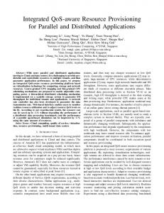
II. S YSTEM M ODEL A traffic conditioning-enabled Radio Network Subsystem (RNS), which is composed of a RNC and one or more Node Bs is depicted in Fig. 1 as our system model. The UEs are distributed within each cell with an omnidirectional base station at the cell center. Neither handover nor mobility is considered in this model.
Node B
Third generation (3G) wireless communication systems like Universal Mobile Telecommunication System (UMTS) are going to provide wideband multimedia services with diverse Quality of Service (QoS). In order to support these disparate services, 3G networks bring a fundamental change since they are expected to be primarily packet-switched instead of circuitswitched. To provide the end users with negotiated QoS, traffic control and resource management play an important role. QoS and traffic management in Internet Protocol (IP) and Asynchronous Transfer Mode (ATM) networks have been widely studied. In ATM networks, a traffic management framework including resource management using virtual paths, connection admission control, usage parameter control, selective cell discard and traffic shaping has been employed [2]. Correspondingly in IP networks, two approaches known as Integrated Service (IntServ) and Differentiated Service (DiffServ) have been proposed to provide end-to-end QoS by Internet Engineering Task Force (IETF) [2], [3]. In the 3G networks, there are currently intensive research work as well as standardization activities in this area [1], [4], [5], [6]. The UMTS QoS architecture has been specified and several end-to-end QoS scenarios have been recommended by 3rd Generation Partnership Project (3GPP) [1], [4]. As a component within the UMTS QoS management entity, traffic conditioning provides conformance of input traffic to the specifications agreed with the bearer service provider. A traffic conditioner may achieve this by traffic shaping or/and traffic policing. The traffic conditioner may be embodied both in a User Equipment (UE) and in the gateway nodes. The concept of traffic shaping has existed for years [7]. There exists mainly two traffic shaping algorithms, namely Leaky Bucket Algorithm defined by ATM Forum and Token Bucket (TB) Algorithm defined by IETF respectively. The latter has been adopted as a reference algorithm for traffic conditioner in UMTS by 3GPP [1]. But for a Code Division Multiple Access (CDMA)-based system like UMTS, very little literature
can be found on how traffic conditioning performs, especially between the UE and the Radio Network Controller (RNC). This paper addresses this issue based on our recent study in traffic conditioning and QoS management in the 3rd generation mobile systems. A traffic shaping and policing framework is proposed according to our system model and corresponding simulation results are presented. The remainder of the paper is organized as follows. The system model and the token bucket algorithm is outlined in Section II. Section III presents our traffic conditioning scheme in UMTS, i.e., traffic shaping at the UE and traffic policing at the RNC, and the simulation model and numerical results are illustrated in Section IV. Finally, the concluding remarks are given in Section V.
RNC
RNS
Fig. 1. System Model: Traffic Shaping and Policing in UMTS
Each UE is expected to use any one of the considered traffic classes. A traffic shaper is employed for uplink traffic on each UE. The packets received at the Node Bs are forwarded to the RNC where the traffic policing function is performed. Our work is focused on the user plane and the relevant signalling protocols between the UE and the RNC are beyond the scope of this paper.
0-7803-7377-4/02/$17.00 (C) 2002 IEEE
A. Traffic classes for UMTS
III. T RAFFIC C ONDITIONING S CHEME IN UMTS
Four traffic classes have been defined by 3GPP [1], based on their delay sensitivity. For the sake of simplicity, we consider two applications, video and WWW, which belong to streaming and interactive traffic classes in UMTS, in our study. Furthermore, we assume that video traffic has tighter constraint on delay requirement but may tolerate comparatively higher packet loss. WWW traffic, on the other hand, does not have tight constraint on delay but is more strict on packet loss ratio. We will take these fundamental characteristics of the traffic classes into consideration when we discuss our numerical results in Section IV. B. Token Bucket Algorithm The token bucket algorithm regulates the bursty traffic in such a way that over a long time period the average allowed rate approaches the desired token rate r asymptotically and over a short time interval the burst size of the traffic is upper bounded by bucket size b. Our implementation of the TB algorithm, which is slightly different from the standard version in [1], is illustrated in Fig. 2, where Token Bucket Counter (TBC) is an internal variable used to record the number of the remaining tokens at any time. With this implementation, three corresponding measures may be taken when a new packet arrives, i.e.,
Traffic conditioner provides conformance between the negotiated QoS for an application and the data unit traffic. This section describes the proposed traffic conditioning framework in UMTS, i.e., employing traffic shaping at each individual UE and traffic policing at the RNC. A. Traffic Shaping at the UE The traffic shaping scenario at the UE is shown in Fig. 3. The TB shaper verifies the conformance of a packet according to corresponding token bucket parameters, shaping the traffic when necessary. More specifically, with our TB implementation, only packets larger than bucket size b will be deemed as non-compliant. As a result, the regulated traffic after shaping will be categorized into two types, either compliant or noncompliant. They are left for further policing at the RNC. Token Rate r Traffic Generator
Bucket Size b
Shaping Buffer
Traffic Shaper Yes Size > b
OK
OK
(To be shaped)
Mark as non−compliant
OK
TBC
Mark as compliant
Yes Size < TBC shaping
L1 b. This type of packet is tagged as not-compliant and will not be dropped at the UE, but left for preferential discarding at the traffic policing point in case of channel congestion. � Case 3: shaped to be conformed. The size of packet k is not larger than the bucket size, but larger than the TBC value at arriving instant, i.e., b � Lk > T BC . In this case, the packet will be enforced to wait by the traffic shaper until there are enough tokens in the bucket. This type of packet is shaped to be conformed and marked as compliant after shaping. We define the time period when a packet is waiting for tokens in the buffer as shaping delay, denoted by Ds .
The scenario will of course introduce traffic shaping delay which consumes part of the total end-to-end delay budget of a service, but the regulated flow is expected to have a lower packet loss ratio instead. One objective of this study is to investigate the tradeoff between shaping delay and non-compliance probability. B. Traffic Policing at the RNC The traffic policing function compares the conformance of the user data traffic with the QoS attributes. Within the capacity of the Bearer Service (BS) manager, policy control is a logical policy decision element which is optional to the UEs and required to the gateways [4]. Traffic policing policy in practice is a network operator choice. More detailed description of the policy framework can be found in [8]. We apply a preliminary policing function in this study by only considering channel congestion status for packet discarding. As depicted in Fig. 4, the policing function consists of traffic classification and policing functionality and is embodied
0-7803-7377-4/02/$17.00 (C) 2002 IEEE
at the RNC. We assume that all packets have passed the Call Admission Control (CAC) phase. The classification function simply checks the header of every received packet and forwards the corresponding information for further policing, according to its traffic class as well as conformance status. Depending on the header status of a packet forwarded from the classification function, the policing element at the RNC will perform corresponding policies on each individual packet. For non-compliant data packets, they will be acknowledged only if the channel is not congested, i.e., the total interference level by summing of all connections does not exceed the threshold. Otherwise they will simply be discarded. For non-compliant data packets, the load calculation will take into account both compliant and non-compliant packets at first, if the load exceeds the threshold, the non-compliant packets will be dropped preferentially. A conformed packet could also be discarded if there are too many concurrent compliant packets on the channel. Packet Arrival
Classification Header check No Yes Compliant No Policing
Number_non
Number_com liant ++
compliant ++
Load calculation for for all packets
Congested
Congested Yes
Dicard the noncompliant packet
Discard the compliant packet
Packet_loss_ noncompliant ++
Packet_loss_ compliant ++
IV. S IMULATION AND N UMERICAL R ESULTS A system level simulation model has been implemented to evaluate the performance of our traffic conditioning-enabled RNS. All simulations are carried out with 10 random seeds which give us a 95% confidence interval. Throughout the context, the discarding probability Pd (referred to also as packet loss ratio sometimes) is defined as the total number of packets discarded at the RNC divided by the total number of packets with the same marking received at the RNC. For example, the discarding probability for compliant packets Pdconf is the number of discarded compliant packets divided by the total number of packets marked by the traffic shaper as compliant. The shaping delay Ds is the average value by all generated packets, and �non is the probability of noncompliance among all generated packets.
We apply On-Off traffic models to both traffic classes in our simulation. The packets are generated according to their packet length distributions at the application layer. Even though the packets could arrive at any time instant according to corresponding interarrival time distribution, they are buffered in the queue and a new packet will not be sent out until the preceding one has finished its service. In other words, the same UE cannot send more than one packet at the same time. No segmentation happens to the generated packets and a protocol header at IP layer is appended to packets before traffic shaping.
No
Yes
P
A. Traffic Model Consideration
Load calculation compliant packets
No
where (Eb =No )i is bit energy to noise ratio required for desired BER of service i, W is the chip rate (3.84 Mcps in 3G), Ri is the information bitrate of service i, �i is the activity factor of service i, f is the interference factor from adjacent cells (i.e. ratio between adjacent cell interference and own cell interference). The total load �total in a cell is the sum of the individual loads with different services from all existing connections u (only uplink is considered here), i.e., �total = N i=1 �i , where Nu denotes the number of calls currently in service. We define that the channel is ’congested’ if the total load �total exceeds the pre-defined threshold. The (Eb =No )i and �i values used in our studied case are listed in Table I.
TABLE I T RAFFIC M ODEL IN S IMULATION
Statistics
Fig. 4. Traffic Policing at the RNC
C. ’Congestion’ Calculation on CDMA Channel The 3G networks are CDMA based mobile systems with ’soft’ capacity. The wireless channel will not really be ’congested’ as load increases, but the quality of all ongoing connections will be degraded by the newly added-on users instead. As there is no ’congestion’ definition for CDMA channel, we employ the well known Pole capacity for our ’congestion’ calculation of CDMA channel. Assuming perfect power control and negligible background thermal noise, the individual load of service i denoted as �i can easily be calculated by [9]:
�i =
(Eb =No )i
W=Ri
�
�i � (1 + f )
(1)
Traffic class Ave. Bitrate Ra Peak Rate Rp (Eb =No )i Activity factor �i Interarrival Time Packet Length Token Rate r Bucket Size b Bucket Size ^b
Video
WWW
28 Kbps 40 Kbps 7.8 dB 0.699 Constant (135.86 ms) Pareto with cutoff (1.7, 1864 bits, 12000 bits) 28.235 Kbps 5754 bits 8221 bits
30.4 Kbps 64 Kbps 6.7 dB 0.475 Exponential (75.64 ms) Pareto with cutoff (1.1, 652 bits, 12000 bits) 34.631 Kbps 5160 bits 10865 bits
For both traffic classes, we assume that the packet size is Pareto(m; �; M ) distributed with cut-off M , where m denotes
0-7803-7377-4/02/$17.00 (C) 2002 IEEE
the minimum size and � is the shape factor. The cut-off is set to be equal to well-known MTU size of 1500 bytes (12000 bits). The interarrival time for video is assumed to be uniform distributed while it is exponentially distributed for WWW. The traffic models used in simulation are parameterized and listed in Table I.
0.3
Discarding Probability for Video Traffic Class
Without shaping With shaping
B. Parameters Acquisition for Token Bucket Algorithm Even though token bucket is a well recognized shaping algorithm, determination of the TB parameters is not a simple task. It is application dependent and there is no standardized algorithm for deciding r and b. According to [4], the average bitrate Ra from the source is used for token rate r calculation and the peak bitrate Rp is used for bucket size b calculation. A protocol header with length Lh is included in the calculation. we formulate the algorithm as follows, where ÆT denotes the sampling interval of the source data (the inverse of ÆT is the number of frames per second):
+ Lh )=ÆT = Ra + Lh =ÆT
b = Rp � ÆT
+ Lh
confidence level = 95%
0.15
0.1
0.7
0.8
0.9 Relative Traffic Load
1
1.1
1.2
Fig. 5. Discarding Probability for Video Traffic
0.25 Without shaping With shaping
(2) (3)
Rp Ra
sample size = 10, T−distribution
0.2
0 0.6
Empirically we find the bucket size defined by equation (3) is too conservative and may not be suitable for certain type of traffic. The bursty property of the traffic flow has not been considered. Therefore, we propose to define the bucket size with the following equation, where denotes the burstiness of a traffic flow and is defined as = Rp =Ra :
^b = b � = b �
Confidence Interval:
0.05
Discarding Probability for WWW Traffic Class
r = (Ra � ÆT
0.25
0.2
Confidence Interval: sample size = 10, T−distribution confidence level = 95%
0.15
0.1
0.05
(4) 0 0.6
The obtained token bucket parameters for both traffic classes are listed in the last three rows of Table I, where we assume a compressed RTP/UDP/IP header (4 octets) for video and a TCP/IP header (40 octets) for WWW. C. Numerical Results The performance of our studied system is evaluated at various network loads and the results are discussed in this subsection. We use a relative system load �� here to represent how heavy the channel is loaded, with �� = 1 implying that the system has reached its channel capacity. But we allow �� to exceed 1 to a small degree due to the ’soft’ capacity property the CDMA channel. C.1 Discarding Probability With versus Without Shaping Our first observation is to inspect the impact of traffic shaping by comparing the discarding probability with versus without shaping for both traffic classes. To make a fair comparison, we set the bucket size to be b = 12000 bits. This implies that all generated packets will be conformed after shaping and the total amount of packets generated during simulation time is almost the same for both with and without traffic shaping cases. Without shaping scheme means there is no token bucket attached to the traffic generator. The simulation results are depicted in Figures 5 and 6. It is shown, for both traffic classes, that the discarding probability with traffic shaping is smaller than Pd without traffic shaping, for all ranges of system load. The heavier the system load, the larger the difference. When the traffic load is
0.65
0.7
0.75
0.8 0.85 0.9 Relative Traffic Load
0.95
1
1.05
1.1
Fig. 6. Discarding Probability for WWW Traffic
light (relative load �^ < 0:7), very few packets are lost for both cases. This means that for light traffic load, there is no need to do traffic shaping, because the introduced shaping delay does not help with the packet discarding probability. But as the traffic load becomes heavier, the regulated packets are more likely to survive over the wireless channel. The heavier the system load is, the more important it is to use traffic shaping for bursty traffic. C.2 Tradeoff between Shaping Delay and Probability of Noncompliance Keeping the token rate as defined by equation (2) and allow bucket size b to be variable, we observe the impact of b on probability of non-compliant packets �non and shaping delay Ds in Figures 7 and 8. Note that with our traffic shaping scheme, only packets larger than b will be judged as non-compliant. Therefore, based on our traffic model, �non is mathematically 1 available. The simulations show exactly the same results for both traffic classes as depicted in Fig. 7. The figure shows 1 Given Pareto(m; �; b) distribution with cut-off at b, with probability density function fx (x), the probability that a packet with length L > b, which means �non in our case, can be calculated by �non = P rob(L > b) = fx (x)dx = (m=b)� .
R1 b
0-7803-7377-4/02/$17.00 (C) 2002 IEEE
that �non decreases monotonically as b increases. On the other hand, Fig. 8 shows the shaping delay Ds increases monotonically as b becomes larger. As �non and Ds are two important QoS parameters, there is always a tradeoff between them. For example, for delay-sensitive application like streaming video, we would like to use a comparatively smaller b for having a shorter delay despite of a possible larger packet loss. For nonreal-time applications, we would prefer to use a larger b for a small packet loss, despite of the fact that a longer delay may be introduced. Fig. 8 also shows that the shaping delay for video is more sensitive to token bucket size, i.e., Ds grows faster for video as b increases. This means that we have to sacrifice more delay if we use a larger bucket size for video traffic. Video, r = 28.235 bps WWW, r = 34.631 bps 0.25 Probability of Non−compliant Packets
Confidence Interval: sample size = 10, T−distribution confidence level = 95%
0.15
0.1
0 3000
4000
5000
6000 7000 8000 Bucket Size b (bits)
9000
10000
11000
Fig. 7. Probability of Non-compliance as b varies
4 Video, r = 28.235 bps WWW, r = 34.631 bps Confidence Interval:
Shaping Delay at the Token Bucket (ms)
sample size = 10, T−distribution
3
5754 ^b = 8221 b = WWW 5160 ^b = 10865
8.01
2.20
3.44
29.55
10.18
1.76
1.01
29.07
4.55
2.43
4.77
30.88
V. C ONCLUSIONS AND F UTURE W ORK
0.05
3.5
Video
b=^b(bits) �non (%) Ds (ms) Pdconf (%) Pdnon (%) b = 14.61 1.37 0.74 26.68
longer delay, larger Pdconf and Pdnon . Note there is a difference between the performance of video and WWW. Recall the results in Fig. 8 where Ds is less sensitive to bucket size for WWW, it means that we have obtained a much lower �non with ^b at a very low cost of Ds . As the non-compliant packets are much more likely to be discarded at any other network nodes, using ^b enables us, especially for WWW traffic, to have a much lower overall packet loss ratio. The advantage of using ^b is not so obvious for video flow as for WWW flow.
0.3
0.2
TABLE II C OMPARISON OF b AND ^b
confidence level = 95%
We have presented a traffic conditioning framework for heterogeneous traffic classes in UMTS radio access network. By comparison, we conclude that traffic shaping at the UE is generally necessary for QoS provisioning. Using token bucket algorithm as the traffic shaper, there is always a tradeoff between shaping delay and noncompliance probability, and the tradeoff must be made by considering the traffic characteristics of different traffic classes. Based on this work, we are going to study the conformance consistency of the regulated traffic flow at other network gateway nodes for end-to-end QoS provisioning in 3G networks. ACKNOWLEDGMENT The work presented here is part of the TURBAN cooperation between NTNU and Telenor AS.
2.5
2
1.5
R EFERENCES 1
0.5
0 3000
4000
5000
6000 7000 8000 Bucket Size b (bits)
9000
10000
11000
Fig. 8. Shaping Delay at the TB as b varies
C.3 Comparison of b and ^b
We argued earlier that the bucket size b derived from equation (3) is too conservative and may not be suitable for certain traffic classes. Taking burstiness into consideration we can obtain another bucket size ^b. Running the simulations at the same system load, the comparison for b and ^b is tabulated in Table II. The results generally show that we have achieved a much lower non-compliance probability with ^b, at a price of slightly
[1] 3GPP TS23.107v4.0.0, “QoS Concept and Architecture,” http://www.3gpp.org, December 2000. [2] William Stallings, High-speed Networks: TCP/IP and ATM Design Principles, Prentics-Hall,Inc., New Jersey, 1998. [3] David McDysan, QoS & Traffic Management in IP & ATM Networks, McGraw-Hill, N. Y., 2000. [4] 3GPP TS23.207v1.3.0, “End-to-End QoS Concept and Architecture,” http://www.3gpp.org, March 2001. [5] Rajeev Koodli and Mikko Puuskari, “Supporting Packet-Data QoS in Next-Generation Celluar Networks,” IEEE Communications Magazine, vol. 39, no. 2, Feb. 2001. [6] Sudhir Dixit, Yile Guo, and Zoe Antoniou, “Resource Management and Quality of Service in Third-Genration Wireless Networks,” IEEE Communications Magazine, vol. 39, no. 2, Feb. 2001. [7] L. A. R�nningen, “Analysis of a Traffic Shaping Scheme,” in Proc. 10th International Teletraffic Congress, Montreal, Canada, 1983. [8] R. Yavatkar, D. Pendarakis, and R. Guerin, “A Framework for Policybased Admission Control,” RFC2753, IETF, Jan. 2000. [9] Frank Y. Li and Norvald Stol, “A Priority-oriented Call Admission Control Paradigm with QoS Re-negotiation for Multimedia Services in UMTS,” Proc. IEEE Vehicular Technology Conference, May 2001.
0-7803-7377-4/02/$17.00 (C) 2002 IEEE