delay Quality-of-Service (QoS) traffic streams such as Voice over IP and best effort ... New mesh network technologies such as 802.16 (WiMax) and 802.11s are.
Quality-of-Service Provisioning for Multi-Service TDMA Mesh Networks Petar Djukic and Shahrokh Valaee1
⋆
The Edward S. Rogers Sr. Department of Electrical and Computer Engineering University of Toronto 10 King’s College Road, Toronto, ON, M5S 3G4, Canada {djukic,valaee}@comm.utoronto.ca
Abstract. Multi-service mesh networks allow existence of guaranteed delay Quality-of-Service (QoS) traffic streams such as Voice over IP and best effort QoS traffic streams such as file transfer. We present an optimization that performs a linear search for the minimum number TDMA slots required to support the guaranteed QoS flows. At each stage of the search a linear integer program is solved to find if there is a feasible schedule supporting the required end-to-end bandwidth and delay. Our optimization results in a relative order of transmissions in the frame that guarantees a maximum end-to-end delay in the network. The ordering of the transmissions can be used later to find feasible schedules with the Bellman-Ford algorithm on the conflict graph for the network. We use the optimization in numerical simulations showing the efficiency of 802.16 mesh networks with VoIP traffic.
1
Introduction
Wireless mesh networks interconnect access points (APs) spread out over a large geographical area. Wireless terminals (WTs) connect to the access points on their first hop and their traffic is carried by the wireless mesh to the Point-ofPresence (POP) where it can go to the Internet. The POP is the only node in the network connected to the Internet and can also act as a base station (mesh coordinator). Current mesh networks use 802.11 technology to interconnect the mesh backbone [1, 2]. However, 802.11 technology is a decade old and was not designed for mesh networks. In particular, 802.11 lacks the extensions to provide Quality–of–Service (QoS) in multihop wireless environments [3]. New mesh network technologies such as 802.16 (WiMax) and 802.11s are designed to provide QoS with Time Division Multiple Access (TDMA) [4, 5]. In TDMA, end-to-end QoS is negotiated in terms of end-to-end bandwidth reserved for each AP on the links connecting it to the POP. QoS is enforced at each link with scheduled access to the wireless channel. A schedule assigns slots from each TDMA frame to links so that a number of non-conflicting links can transmit simultaneously in each slot. Link bandwidth is given by the number of slots assigned to it in each frame and the modulation used in the slots. ⋆
This work was sponsored in part by the LG Electronics Corporation.
If all slots in a frame are reserved, TDMA mesh networks would not allow statistical multiplexing of best effort data streams at the MAC layer. So, both 802.16 and 802.11s divide the slots in every frame between guaranteed service traffic streams and best effort traffic streams. In 802.16, slots reserved for guaranteed QoS traffic are assigned with the centralized scheduling protocol, while other slots are assigned with the decentralized scheduling protocol. In the centralized scheduling protocol, the mesh coordinator assigns bandwidth to all links in the network based on traffic demands from the APs. On the other hand, in the decentralized scheduling protocol, mesh routers are free to negotiate pairwise TDMA assignments, with no QoS guarantees on the bandwidth. In 802.11s networks, slots dedicated to TDMA access are negotiated in a pairwise fashion, while the rest of the frame is dedicated to best effort service with 802.11 EDCF. In this paper we answer the following QoS provisioning question: What is the minimum number of TDMA slots required to support a required guaranteed QoS in the network? The QoS is specified both in terms of bandwidth and delay, for traffic streams such as Voice over Internet Protocol (VoIP). The endto-end bandwidth of each AP is guaranteed with a TDMA schedule that assigns the appropriate bandwidth to links connecting the AP to the POP. The delay in the network consists of queueing delay due to traffic variations and TDMA propagation delay. TDMA propagation delay occurs when an outgoing link on a mesh node is scheduled to transmit before an incoming link in the path of a packet [6]. In this paper, we assume that the queueing delay is minimized in the network layer with the assignment of link bandwidths and concentrate on scheduling algorithms that guarantee a bound on the TDMA delay. We have shown in [6] that end-to-end TDMA propagation delay accumulates at each hop and can be very large – multiples of TDMA frame duration. In 802.16 frame duration can be as large as 20ms, so TDMA delay can be relatively large compared to the 150ms delay budget required for VoIP quality [7]. We formulate an optimization that minimizes the number of TDMA slots allocated for guaranteed QoS traffic, subject to the constraint that the delay introduced with TDMA scheduling is bellow a given threshold. The bound on TDMA propagation delay can be found by delay budgeting the network across the mesh and the wired backbones. The maximum allowed TDMA delay is found by subtracting the delay due to voice processing and the jitter buffer delay from the overall delay budget [7]. The optimization performs a linear search for the minimum number of TDMA slots. At each step of the search, the optimization increases the number of slots required for guaranteed QoS and solves an integer program that finds a transmission order that supports the required banwidth at each hop, subject to the TDMA delay. The optimization stops as soon as the number of guaranteed slots with a feasible transmission schedule is found. We have shown that with a known transmission order TDMA schedules can be found with the Bellman-Ford algorithm run on the conflict graph for the wireless network [6,8]. Since end-to-end TDMA delay depends on the transmission order alone, it can be distributed to the nodes as a part of their QoS provisioning information, thus making sure that the resulting TDMA schedules have a fixed
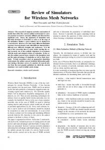
Fig. 1. Multi-service TDMA frames
maximum TDMA delay. Using this method, schedules can be changed dynamically when the bandwidth changes, but still maintain the maximum end-to-end delay. Our optimization is suitable for mesh network planning. During the planning process, locations of mesh nodes are chosen based on the expected interference from neighbouring nodes [4]. With the location known, the expected interference is also known, making it possible to predict maximum modulation at each link, as well as the mesh topology. Given the network topology and the maximum bit-rate on each link, it is possible to plan end-to-end bandwidth to support a specified number of VoIP connections. Our optimization adds an additional level of QoS planning for mesh networks – the scheduling delay through the mesh. We simulate the planing for 802.16 mesh networks with numerical simulations. We examine the effect of 802.16 frame size on efficiency of carrying VoIP traffic. Efficiency is defined as the number of slots required by guaranteed QoS traffic divided by the total number of TDMA slots in the frame. We show that increasing the frame size increases the efficiency in the network almost 50% for a low number VoIP calls, however for a high number of VoIP calls the increase in the efficiency is less than 5%. The efficiency increases with the frame size because as the frame size increases, more transmission orders can produce TDMA schedules with the required bandwidth requirement.
2
Network and Transmission Model
The mesh network is using a time division multiple access (TDMA) MAC protocol [4]. In TDMA MAC protocols, the time is divided into slots of fixed duration, which are then grouped into frames. A fixed portion of each frame is dedicated to control traffic, while the rest of the slots are used for data traffic. The frame has the duration of Tf slots, where Tc of slots are allocated for control traffic, Tg slots are reserved for guaranteed service data traffic and Tb slots are reserved for best effort data traffic (1). We model the mesh with a topology graph connecting wireless routers in the range of each other. We assume that if two routers are in the range of each other,
c3
e2
e3 c13
c5
c2
c8
c7
c9
c6
e1
e6 c1
e3
e1 v1
v2
c12
e5 v3
e2 e4 (a) A four node chain
e6
c11
c10
v4 e4
c4
e5
(b) Conflict graph for the four node topology
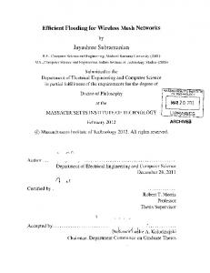
Fig. 2. Chain topology and its conflict graph.
they establish symmetrical links in the MAC layer, so the TDMA network can be represented with a connectivity graph G(V, E, ft ), where V = {v1 , . . . , vn } is the set of nodes1 , E = {e1 , . . . , em } are directional links between neighbouring nodes, and ft : E → V × V assigns links to pairs of nodes. Links are directional, so for a link ek ∈ E, ft (ek ) = (vi , vj ) means that traffic on the link is transmitted from vi to vj . The links operate at different bitrates, which depend on the signalto-noise ratio. Signal-to-noise ratio is divided into several discrete levels and each is associated with its corresponding bitrate. We define the link bitrate as the number of bits transmitted in a TDMA slot, represented with the mapping b : E → {M1 , M2 , . . . , Mmax }, where M1 is the number of bits carried in a slot with the minimum modulation and Mmax is the number of bits carried in a slot with the maximum modulation and coding. We assume that the signal-to-noise ratio of each link depends on the wireless channel alone and not other links in the network, meaning that competing links do not transmit at the same time. Under this model of transmission, in TDMA networks, a receiver can only have one active link at any given time. In a single hop neighbourhood, this means all links interfere with each other. In a two hop neighbourhood, two links, whose nodes are two hops away, interfere if the receiver of one of the links is in the transmission range of the other link. We keep track of conflicts between the links with conflict graphs. Conflict graphs can be defined with a triplet Gc (E, C, fc ), where E is the set of links, C = {c1 , . . . cr } is the set of TDMA conflicts, one for each of the r conflicting pairs of links, and fc : C → {{ei , ej }, ei , ej ∈ E} associates the conflicts with pairs of links. 2 The graph is undirected since conflicts are symmetrical. In this paper, we use a conflict graph with an arbitrary assignment of directions to − → − → − → the arcs, G c (E, C, f c ), where f c : C → E × E. The directed conflict graph 1 2
We use the convention that vn is the POP. We use the notation {·} for unordered sets and (·) for ordered sets, so fc defines an undirected graph.
simplifies the derivation of formulas, however the arbitrary orientation of arcs does not cause any loss of generality. We use the four node example from Fig. 2a to demonstrate how the arcs in the conflict graph are created. The vertices in the conflict graph are the six links from the topology graph. All of the links conflict with each other, except for pairs e1 and e6 and e2 and e5 , so they are not connected (Fig. 2b). The conflict graph has an arbitrary orientation. Link bandwidths are assigned so that a certain number of VoIP connections can be carried between each AP and the POP The assignment of bandwidths is performed during mesh network planning. The assignment of link bandwidths is provided as the maping B : E → R[0,∞) . The scheduling algorithm assigns link bandwith through the number of slots a link can use in a frame d : E → Z[0,T ] . The number of slots required to achieve bandwidth Bi on link ei can be found with: � � Bi Tf TS di = , (1) bi where ⌈·⌉ denotes the ceiling of a real number, Tf is the number of slots in the frame, Ts is the duration of mini-slot in seconds and bi is the number of bits in each slot. We assume that after the link bandwidths have been assigned, there are 2q one-way paths terminating or originating at the POP. The paths connect the POP with q < n − 1 APs acting as VoIP cells for WTs. We denote a path from the POP to node vl with Pl and the path from the node vl to the POP with Pq+l . The set of all paths is denoted with P = {P1 , . . . , P2q }. We use a maping − → function f p : P → E × E to associate a path with its starting and ending link, − → so f P (Pl ) = (ei , ej ) means the the link for the first hop is ei and the link for the last hop is ej .
3
TDMA Scheduling
We present a set of conditions that guarantees that the transmission schedule for guaranteed QoS slots is both valid and conflict-free. The constraints are necessary so that at each stage of the minimization of Tg , we can obtain a feasible schedule for the guaranteed QoS slots. A transmission schedule assigns slots from each TDMA frame to links so that a number of non-conflicting links can transmit simultaneously during each slot. A valid transmission schedule assigns the number of slots allocated to the links due to QoS requirements. A conflict-free schedule ensures that transmissions of conflicting links do not overlap. We define the TDMA schedule, used for guaranteed QoS service slots, with a pair of vectors Sg (π, d), where π = [π1 , . . . , πm ]T are the starting times of the links in the part of the frame allocated for guaranteed QoS and d = [d1 , . . . , dm ]T is the duration of each transmission. The activation times need to be limited to πi ∈ [0, Tg ), ∀ei ∈ E, so that each link transmits in every frame. We note that the schedule is valid by definition, since every link will be scheduled to transmit
Tc (z − 1)Tf
Tg
Tb
zTf
(z + 1)Tf
(z − 1)Tg
Time
dj
di ωi
(z + 2)Tf
ωj
ωi + Tg
zTg
Tg time (z + 2)Tg
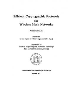
Fig. 3. Conflict-free Conditions
for the number of slots required with its bandwidth assignment. We have defined conditions for conflict-free scheduling in [6]; we briefly summarize those results here. The guaranteed TDMA schedule repeats in every frame, until a new set of link bandwidths is assigned. The slots allocated for guaranteed QoS are always sandwitched between the control slots and the best effort TDMA slots. If we ignore the non-guaranteed QoS slots, we can view the uninterrupted sequence of guaranteed QoS slots on its own axis (Fig. 3). On this axis, the activation times, π, are periodic. Periodicity of the schedule means that the start time πi for link ei actually represents a series of activation times, which can be derived from πi by adding multiples of Tg slots (Fig. 3). We denote with Πi = {πi + zi Tg , zi ∈ Z} the series of activation times for link ei , generated with πi . The normalized activation time πi can be found from any activation time ωi ∈ Πi with the modulo operator: πi = ωi (mod T ). The number of times a link transmits in the frame depends on its starting time and the duration of its transmission. If for some link ei , πi + di ≤ Tg , the link will transmit once per frame. If we assume that the slots in the frame are numbered [0, Tf −1], the transmission takes place in slot Tc +πi with the duration of di slots. On the other hand, if πi + di > Tg , the link will be scheduled twice for transmission in the frame. The first transmission starts in slot Tc , with the duration πi + di − Tg slots and the second transmission start in slot Tc + πi with the duration of Tg − πi slots. So, our scheme limits the number of transmissions by any link to at most twice in a frame. This is good for protocols such as 802.16 where the overhead of each transmission can be as much as 324 bytes at the highest modulation [4]. In [6], we also show how this method can be extended to find schedules for multiple activation times in the guaranteed QoS part of the frame. The conflict-free conditions for a schedule can be expressed in terms of points in the sequences Πi , ∀ei ∈ E. We have shown in [6] that a schedule is conflict− → free, if for any two conflicting links ei and ej whose conflict is ck ∈ C : f c (ck ) = (ei , ej ): d i ≤ ω j − ω i + pk T g ≤ T g − d j , (2) where ωi ∈ Πi and ωj ∈ Πj and pk = 0 if ωj − ωi > 0 and pk = 1 if ωj − ωi < 0. Variable pk specifies a relative order of transmissions, which prompts us to refer to it as the “transmission order” in the rest of the paper. A schedule is conflict
free if (2) is true for all conflicts in the network. Fig. 3 shows why (2) is necessary for the schedule to be conflict-free. In the figure pk = 0, so we are comparing the timing of ei ’s transmission to the first transmission of ej that follows it. Clearly, it is necessary that ωj ≥ ωi + di since ej cannot start its transmission before ei finishes. Also, the next transmission of ei should be after ej has finished its transmission, so ωi + Tg ≥ ωj + dj . Full proof of necessity and sufficiency of (2) can be found in [6]. The conflict free conditions provide a strategy that can be used to find feasible conflict-free schedules. The strategy is to simultaneously look for an ordering vector p = [p1 , . . . , pr ]T and a set of ωi ∈ Πi , ∀i ∈ E, satisfying (2) for all conflicts. This search problem was shown to be NP-complete in [9], by reduction to Graph K-Colourability. However, for a fixed transmission order, a feasible schedule can be found with the Bellman-Ford algorithm on the conflict graph [6, 8]. We show next that the TDMA delay depends on the transmission order and a feasible ω = [ω1 , . . . , ωm ]T . However, we also show that the feasible ω can be compressed into a single parameter, leading us to a two step procedure to optimize TDMA delay. First, TDMA propagation delay is minimized subject to an existence of a feasible schedule. Second, the transmission order and the feasibility parameter are distributed among the mesh nodes, so they can find the transmission schedule using the Bellman-Ford algorithm.
4
TDMA Delay
We show how to calculate and minimize return trip TDMA propagation delay in the mesh in [6]. While that approach is appropriate for TCP flows, it is not appropriate for VoIP connections, since perceived voice quality depends on the one-way delay between a sender and its receiver [7]. In this section, we find the expression for one way TDMA propagation delay on a path, using results from [6]. We first find TDMA propagation delay at single router on the path and then add up the delay at every router on the path to find an expression for the one-way end-to-end TDMA delay on the path. TDMA propagation delay occurs if an ingress link is scheduled to transmit after an egress link on the router. So, on a single mesh router it is measured as the time between the transmission of an ingress link, to the time when the egress link transmits, excluding the queueing delay. We show in [6] that the TDMA propagation delay experienced by a packet traversing a mesh router from an ingress link ei to an egress link ej is given by: ( − → ω j − ω i + pk T f if f c (ck ) = (ei , ej ) ∆k = (3) − → ωj − ωi + (1 − pk )Tf if f c (ck ) = (ej , ei ), where ck ∈ C is the conflict connecting the two links in the conflict graph and ωi , ωj and pk correspond to a fixed feasible schedule S(π, d). For example, if − → f c (ck ) = (ei , ej ) and pk = 0 it is easy to see that ∆k = ωj − ωi since the
packet can be transmitted in the same frame on both links. However, if pk = 1, ∆k = ωj − ωi + Tf since the packet has to wait for new frame to be transmitted by ej . The total TDMA delay on a path is found by adding up the delay at each router on the path in the topology graph. We now show that each path in the topology graph corresponds to a path in the conflict graph, which lead us to a simpler formulation of the TDMA delay. The path in the conflict graph, corresponding to a path in the topology graph, can be obtained by traversing − → − → the conflicts in G c (V, E, f c ) corresponding to conflicts between ingress and egress links at the each router in the path. For example, path e1 e3 e5 in the four node topology shown in Fig. 2a, corresponds to the path c6 c9 in Fig. 2b. We represent the paths in the conflict graph with r-sized vectors in the {−1, 0, 1}r path space of the conflict graph [10]. The meaning of the entries of θ l = [θ1 , . . . , θr ]T , corresponding to path Pl in the conflict graph, is: if ck ∈ θ + 1, l ∀ck ∈ C, θk = −1, if ck ∈ θ + (4) l 0, otherwise,
+ where θ + l is the set of arcs in the positive direction of θ l and θ l is the set of + arcs in the negative direction of θ l . For example, the path emphasized in Fig. 2 corresponds to the vector θ = [0, 0, 0, 0, 0, 1, 0, 0, 1, 0, 0, 0, 0]T . The total delay on path Pl is found by adding up the single hop delay incurred for the conflicts between ingress and egress links at each router in the path. The delay on path Pl is given by:
D(Pl ) =
r X
k=1
r � � � � X θk τk + pk Tf I(θk > 0) + θk τk + pk Tf − Tf I(θk < 0) (5) k=1
− → where τk = ωj − ωi is the tension for the conflict ck , f c (ck ) = (ei , ej ), and I(·) is the indicator function, 0 when its argument is false and 1 when its argument is true. A well know property of tensions is that the sum of tensions along a path is equal to the tension between end vertices [10]. This property allows us to express the delay on the path with: D(Pl ) = ωj − ωi +
θ Tl pTf
+
r X
Tf I(θk < 0),
(6)
k=1
− → where ei and ej are the first and the last link on the path, f P (Pl ) = (ei , ej ), and we used vector product to express the summation of θk pk on the path. Since the last term in the delay is a constant depending only Pron the orientation in the conflict graph, we will denote refer to it with Dl = k=1 Tf I(θk < 0) for path Pl in the rest of the paper.3 3
Dl depends on the orientation of the conflict graph. However, we show in [6] that since p also depends on the orientation of the conflict graph, the total TDMA propagation delay does not change if the orientation changes.
5
QoS Provisioning for Minimum Delay
In this section, we present an algorithm that can be used to find the minimum number of guaranteed QoS slots, required to support a given bandwidth subject to maximum TDMA delay. The maximum TDMA delay is found with delay budgeting and is denoted with Dmax . We present the algorithm first and then show how to compress a feasible schedule associated with the minimum Tg into a single parameter. The algorithms starts with Tg = 1, and increments Tg , until a feasible transmission order p and a schedule ω are found. At each step, the algorithm solves the following {0, 1}-integer linear program: Find ω, p s.t.
(7a)
ωj − ωi +
θ Tl pTf
≤ Dmax − Dl ,
di ≤ωj − ωi + pk Tg ≤ Tg − dj , m
− → ∀Pl ∈ P, f p (Pl ) = (ei , ej ) − → ∀ck ∈ C : f c (ck ) = (ei , ej )
r
ω ∈ Z , p ∈ {0, 1} .
(7b) (7c) (7d)
The linear program finds a feasible ω and a feasible p. The first 2q constraints, (7b), ensure that the total delay on all paths is less then Dmax . The next r constraints, (7c), ensure that there is a feasible schedule satisfying the delay constraints. The algorithm either runs until a feasible set of ω and p is found or until Tg reaches Tf − Tc . Since we perform a linear search of all possible values of Tg , we are guaranteed to find the minimum Tg for which there is a feasible schedule with a TDMA delay less than Dmax on every path . In order to allow the mesh routers to schedule links without the knowledge of a specific feasible ω, we introduce a new variable into the optimization. The new variable represents the maximum allowed difference between the activation time of the last link on a path and the first link on the path. We substitute t instead of the the first two terms in (8), so delay on the path becomes: D(Pl ) = t + θ Tl pTf + Dl ,
∀Pl ∈ P.
(8)
The required constraint on TDMA delay, (7b), is still true if: ωj − ωi ≤ t,
− → ∀Pl ∈ P, f p (Pl ) = (ei , ej ).
(9)
This leads us to the following {0, 1}-integer program, to be run for each Tg , instead of (7): Find ω, p, t s.t.
t+
θ Tl pTf
(10a) ≤ Dmax − Dl ,
di ≤ωj − ωi + pk Tg ≤ Tg − dj , ωj − ωi ≤ t, ω ∈ Zm , p ∈ {0, 1}r , t ∈ R,
∀Pl ∈ P − → ∀ck ∈ C : f c (ck ) = (ei , ej ) − → ∀Pl ∈ P, f p (Pl ) = (ei , ej )
(10b) (10c) (10d) (10e)
where the combination of (10b) and (10d) replaces (7b). Using the symmetry between the paths we can see that (10d) is equivalent to half as many double sided constraints: −t ≤ ωj − ωi ≤ t,
− → ∀Pl , l = 1, . . . q, f p (Pl ) = (ei , ej ).
(11)
So when p and t are fixed a feasible schedule can be found using the BellmanFord algorithm on a modified conflict graph. We create a new scheduling graph, − → GS (E, Cs , f s ), from the conflict graph by adding arcs between the start link and the end link of the first for every path originating at the POP. This adds q additional arcs to the conflict graph to create CP = C ∩ {cr+1 , cr+q } arcs for the scheduling graph. The function connecting the arcs of the scheduling graph − → − → − → to the links f s by mixing f c and f p : (− → − → f c (cl ), if l ≤ r (12) ∀cl ∈ Cs , f s (cl ) = − → f p (Pl ), if r < l ≤ q + r. Since the scheduling also has a set of inequalities associated with every arc, the schedules can be found from the scheduling graph the same way they are found from the conflict graph [6, 8].
6
Numerical Results
In this section we present numerical results showing how well 802.16 mesh networks work with VoIP traffic. In 802.16 mesh networks, Tg is specified as the network parameter MSH-CSCH-DATA-FRACTION [4, p. 86]. This parameter specifies the percentage of each frame that should be used for centralized TDMA scheduling. Our numerical optimization simulate multihop 802.16 mesh networks and find the percentage of the frame that should be scheduled with the 802.16 centralized scheduling protocol, so that VoIP QoS is met. The results from this section can also be used to decide the frame sizes for 802.16 mesh networks. We assume that WTs are using the G.729 codec to encode voice. With the G.729 codec, the bandwidth of each VoIP call is 8.0kbps [7], so we assume that the end-to-end bandwidth required by each VoIP call is 8.0kbps. We use the delay budgeting presented [7] to derive the bound on TDMA propagation delay required in the network. The delay budgeting assumes that the voice quality requires an end-to-end delay of 150ms. The delay not consumed by voice processing consists of the jitter buffer delay of 60ms and 30ms delay for the Public Switched Telephone Network (PSTN). We assume that the PSTN delay is fixed and examine how much jitter delay can be allowed in the Internet. We use the values of Dmax = 40ms and Dmax = 60ms, corresponding to the jitter buffer delay of 20ms and 0ms, respectively. We have generated 100 random mesh network topologies, and performed mesh network planning for each of them. Each topology was generated by placing the POP in the center of a square area 500m × 500m and then randomly placing
n = 29 mesh nodes in the square area. The topology graph for the network is created from the transmit power of the nodes and signal path loss. Each mesh node is given transmit power of 40dbm. We use the sample calculation given in [4] and the the ECC-33 path loss model for medium city environments [11, 12] to calculate the path loss due to the distance between the nodes. The modulation on each link is chosen based on received signal strength, as specified in [4, p. 765]. We assume that the network is using OFDM with 10Mhz bandwidth, so the OFDM symbol size is 25µs [4, p. 812]. The area where the mesh is located is partioned into 25 cells, each with the radius of 50m. The purpose of the cells is to simulate short range 802.11 APs, which allow WTs to connect to the network. Each cell is assigned the mesh router closest to it as the AP. We use the minimum spanning tree algorithm to find a tree topology connecting all the mesh routers to the POP. Each router is assigned an end-to-end bandwidth of designed to support a certain number of VoIP calls, and the end-to-end bandwidths are used to calculate link bandwidths required on every link in the network. The number of guaranteed service slots required on every link is calculated from the modulation used on the link and the symbol size.
Table 1. Percentage of Slots Required for VoIP Traffic (Dmax = 40ms) 802.16 Frame Size Calls 4 8
2.5ms 5.0ms 10.0ms 20.0ms 47% 55%
29% 53%
27% 51%
23% 46%
Table 6 summarizes the results of our numerical simulations for Dmax = 40ms. The results for Dmax = 60ms are within 2% of those values. The number of slots required for guaranteed traffic does not decrease if the delay is allowed to increase up to 60ms. From the table, we conclude that it is advantageous to increase the frame size since this increases the efficiency of 802.16, were efficiency is defined as the number of slots needed to carry VoIP traffic divided by the total number of slots in the frame. We have used the GNU Linear Programming Kit (GLPK) [13] to perform the main {0, 1}-integer optimization in the search problem. GLPK uses exhaustive search to find feasible p vectors. We have found that, for most scenarios, this search is in the order of a few minutes on a Xeon processor. However, since we are repeating the minimization hundreds of times, we have limited the exhaustive search performed by the GLPK solver to at most 10, 000 p vectors. This makes our results less accurate, however, it allows us to perform an exhaustive MonteCarlo simulation.
7
Conclusion
We have presented a method to minimize the number of TDMA slots required to support a given end-to-end QoS in mesh networks. Our optimization works by performing a linear search over the number of slots required to support the given end-to-end bandwidth. At each iteration of the search, the optimization solves a {0, 1}-integer program that finds an order of transmissions in the frame, so that the maximum TDMA propagation delay is kept bellow a given QoS level and end-to-end bandwidths can be scheduled. It is important to limit the TDMA propagation delay for traffic streams such as VoIP calls, requiring a guaranteed end-to-end delay. The optimization method in this paper is appropriate for mesh network planning, since the order of transmissions can later be distributed to the nodes to create schedules. The schedules will have the same maximum TDMA propagation delay, since the delay depends on transmission ordering in the frame. We have also used numerical simulations to show the efficiency of 802.16 network in carrying VoIP traffic.
References 1. Camp, J., Robinson, J., Steger, C., Knightly, E.: Measurement driven deployment of a two-tier urban mesh access network. Technical Report TREE0505, Rice University (2005) 2. Nortel Networks: Wireless mesh network - extending the reach of wireless lan, securely and cost-effectively. http://www.nortelnetworks.com/solutions/wlan/ (2003) 3. Xu, S., Saadawi, T.: Does the IEEE 802.11 MAC protocol work well in multihop wireless ad hoc networks. 39(6) (2001) 130–137 4. IEEE: IEEE standard for local and metropolitan area networks part 16: Air interface for fixed broadband wireless access systems (2004) 5. IEEE: 802.11 TGs MAC enhacement proposal. Protocol Proposal IEEE 802.1105/0575r3, IEEE (2005) 6. Djukic, P., Valaee, S.: Link scheduling for minimum delay in spatial re-use TDMA. In: INFOCOM. (2007) 7. Goode, B.: Voice over internet protocol VoIP. Proceedings of the IEEE 90(9) (2002) 1495–1517 8. Djukic, P., Valaee, S.: Distributed link scheduling for TDMA mesh networks. Wirlab technical report, University of Toronto (2006) 9. Odijk, M.A.: Railway Timetable Generation. Ph. D., Technische Universiteit Delft (1998) 10. Rockafellar, R.T.: Network Flows and Monotropic Optimization. John Wiley & Sons (1984) 11. Electronic Communication Committee (ECC) within the European Conferenceof Postal and Telecommunications Administration (CEPT): The analysis of the coexistance of FWA celss in the 3.4-3.8 GHz band. ECC Report 33 (2003) 12. Abhayawardhana, V., Wassell, I., Crosby, D., Sellars, M., Brown, M.: Comparison of empirical propagation path loss models for fixed wireless access systems. In: 61st IEEE Vehicular Technology Conference (VTC). (2005) 13. Makhorin, A.: GNU linear programming kit. Technical Report Version 4.8 (2005)