Quantum Dot Cluster State Computing with Encoded Qubits Yaakov S. Weinstein,1, ∗ C. Stephen Hellberg,1, † and Jeremy Levy2, ‡ 1
Center for Computational Materials Science, Naval Research Laboratory, Washington, DC 20375 2 Dept. of Physics and Astronomy, University of Pittsburgh, Pittsburgh, PA, 15260
A class of architectures is advanced for cluster state quantum computation using quantum dots. These architectures include using single and multiple dots as logical qubits. Special attention is given to the supercoherent qubits introduced by Bacon, Brown, and Whaley [Phys. Rev. Lett. 87, 247902 (2001)] for which we discuss the effects of various errors, and present means of error protection.
arXiv:quant-ph/0506032v1 3 Jun 2005
PACS numbers: 03.67.Lx, 03.67.Pp, 75.10.Jm
Cluster state or one-way quantum computation [1] is a measurement based scheme for universal quantum computation formally equivalent to the traditional circuit method [2]. The basis of the scheme is the cluster state [3], a highly entangled state on which measurements alone can perform universal quantum computation. To create the cluster state one rotates all qubits in a lattice √ of at least two dimensions into the state |+i = 1/ 2(|0i + |1i), followed by an Ising interaction exp(−i π4 σzj σzk ) between all nearest neighbor qubits j, k and single qubit σzj rotations. Due to the centrality of the Ising interaction in cluster state creation, proposed implementations of cluster state quantum computation [4, 5, 6, 7, 8] have not included spin systems which evolve via the Heisenberg exchange interaction. However, these systems do allow for cluster state computation. In this work we discuss several cluster state computation models for systems with Heisenberg interaction. We outline the hardware requirements and possible error operators in each model. Encoding logical qubits (LQs) into several Heisenberg coupled physical qubits allows for a natural Ising-like inter-LQ evolution, reduces hardware requirements, and allows for protection against various forms of errors and decoherence. While these models are applicable to any Heisenberg coupled systems we refer specifically to quantum dot implementations. After creation of the cluster state, the desired algorithm is mapped onto the cluster state lattice by means outlined in [1, 2] and extra qubits are removed by measuring them along z. Computation is then performed by measurement of the remaining qubits along bases in the x − y-plane. For certain gates, such as arbitrary single qubit rotations, the outcome of a given measurement is
∗ Present address: Quantum Information Science Group, MITRE, Eatontown, NJ, 07724 To whom correspondence should be addressed; Electronic address:
[email protected] † Electronic address:
[email protected] ‡ Electronic address:
[email protected]
necessary to determine in which basis future measurements should be performed [1]. In such cases the measurements must be performed in a specified order. For some systems, measurements along the z-axis [9] may be easier than those in the x − y-plane. In this case one can rotate the qubit to be measured from the x − yplane along z and perform the measurement. For example, a process equivalent to measurement along an axis an angle φ away from positive x ˆ, is a π/2-rotation about the axis φ − 90◦ and a measurement along z. Alternatively, all of the qubits can be rotated as long as they are rotated back after the measurement. We will make use of the commutivity between rotations and measurement in the models below. The first architecture we present for quantum dot cluster state computation is a two dimensional array of quantum dots, or physical qubits (PQs), each acting as a LQ. After initialization, the dots can be rotated into the state |+i using a global magnetic field about yˆ. For a pair of dots, an Ising interaction can be performed by evolution of the Heisenberg coupling, U1 = exp(−i π8 σ 1 · σ 2 ), applying a π rotation to one of the dots about zˆ, and again applying U1 . For an array of dots an Ising interaction between all nearest neighbors can be implemented by turning on all nearest neighbor Heisenberg couplings and applying π)z rotations to every other dot. This requires individual addressability of the dots, via g-factor engineering or local magnetic fields, or alternative placement of two species of quantum dots (A and B) in which all dots of a species are addressed equivalently and without effecting dots of the other species. We note that turning on all nearest-neighbor couplings at once introduces many-body terms into the Hamiltonian [10]. Instead, the cluster state can be built in four steps as in Fig. 1a. The construction is such that no qubit undergoes more then one coupling at each step. After the coupling terms single dot (or species of dot) rotations are needed to complete the cluster state. Readout of the individual quantum dots can be accomplished via any of the suggested single-dot measurement schemes[11]. Certain of these schemes may be limited to
2 a
b
A
B
A
B
A
B
A
B
B
A
B
A
B
A
B
A
A
B
A
B
A
B
A
B
B
A
B
A
B
A
B
A
subspace. However, a logical π)z rotation on one of the LQs refocuses the unwanted part of the evolution leaving a logical Ising coupling, σzjL σzkL . In addition, this encoding is a decoherence free subspace (DFS) with respect to collective dephasing [14].
FIG. 1: (Color online) Two species quantum dot cluster architectures. a) A two specie cluster where each physical qubit, or dot, is a logical qubit. The cluster state for this architecture can be built in four coupling steps each requiring the application of U1 , π)z rotation on species A or B, and again U1 . Four steps are necessary in order that a qubit will not interact with more than one neighboring qubit at each step. The connecting lines show which dots are coupled at each step: dashed, dash-dot, dash-dot-dot, and dash-dot-dot-dot, the order of the steps being unimportant. b) Each logical qubit is composed of two physical qubits, one from each species A and B (joined by solid lines). To build a cluster state one uses the intra-LQ coupling to create the |+i state on each qubit, and three coupling steps (dashed, dash-dot and dash-dot-dot lines) each consisting of inter-LQ coupling and single LQ zrotations.
measurement along the z-axis [9] in which case all of the qubits can be rotated (as explained above) using a global magnetic field. Let us summarize the necessary components for this architecture. The hardware requirements are a twodimensional lattice of individually addressable dots or alternative placement of two species of dots in which each species is addressed equivalently without affecting the other species. In addition, it is necessary to control the interactions between dots and perform single quantum dot measurements. We can remove the necessity of performing logical operations with magnetic fields by encoding LQs into two physical qubits, one of each specie of dot (where the species have different g-factors). Again the dots are arranged in a two dimensional lattice and placed in a magnetic field [12]. The logical qubit states are: |0L i = |0A 1B i |1L i = |1A 0B i.
(1)
This encoding allows for the performance of single LQ x-rotations by turning on the Heisenberg coupling between the physical qubits within the LQ (the intra-LQ coupling) and z-rotations by simply waiting and allowing the Zeeman term to evolve. Rotations about zˆ require a time ∼ 1/Bz ∆g, where Bz is the strength of the magnetic field and ∆g = gA − gB is the difference in species g-factor (an alternate method to perform z-rotations is given in [13]). Inter-LQ interactions are done via the Heisenberg coupling connecting two LQs. The latter operation takes part of the system state outside the LQ
With the above encoding a cluster state can be created as follows. Rotate all LQs into the |+i state via intra-LQ couplings. An Ising coupling between LQs is performed as described above. The coupling is applied in three steps so as not to introduce multiple couplings on one physical qubit. Each step requires logical π)z rotations on alternate LQs only. This can be done by via the quicker logical π)x rotations on the remaining LQs. Finally, single LQ rotations are done using the Zeeman interaction. The required lattice for this architecture and the scheme for cluster state construction is shown in Fig. 1b. Measurement of the LQs can be done by measuring the individual quantum dots as above or directly [12] via singlet-triplet measurements [15]. To summarize, the requirements for cluster state computation using LQs encoded in two physical qubits are two species of quantum dots placed alternately in a twodimensional lattice. The two species g-factors should be different enough such that LQ z rotations can be done within a reasonable time. In addition, it is necessary to control the interactions between dots and perform either single dot or singlet-triplet measurements. The previous cluster state constructions all require the utilization of more than one species of physical qubit. By incorporating more advanced logical qubits we can remove this necessity, perform computations using just the Heisenberg interaction and singlet-triplet measurement, while making the LQs more robust against a variety of possible errors. In addition, cluster state construction becomes easier since the Ising interaction is the natural coupling between the logical qubits. An example of this type of DFS is the three physical-qubit encoding discussed in Ref. [16] which provides DFS protection against collective errors. The inter-LQ Hamiltonian for this three-qubit encoding is σzjL σzkL plus single LQ z-rotations which can then be modified by intra-LQ couplings. A more robust encoding is the supercoherent qubit (SQ) of Ref. [17]. SQs minimize decoherence by forcing all reasonable interactions with the environment to overcome an energy gap which exists between the logical qubit subspace and other states of the system. Environment induced collective errors or single physical qubit local errors must overcome this energy gap. A SQ in its idle state consists of four physical qubits with equal non-zero Heisenberg coupling (equal to 1 for simplicity) between all physical qubit pairs. An orthogonal basis for the doubly degenerate ground state comprises of singlet or triplet states between physical qubits
3 1,2 and physical qubits 3,4: 1 (| ↑↓i − | ↓↑i)1,2 ⊗ (−| ↑↓i + | ↓↑i)3,4 |0L i = 2 1 |1L i = √ (| ↑↑↓↓i + | ↓↓↑↑i) 3 1 − √ (| ↑↓i + | ↓↑i)1,2 ⊗ (| ↑↓i + | ↓↑i)3,4 . (2) 2 3 The state |0L i incorporates the singlet state between spins 1 and 2 and spins 3 and 4. The state |1L i incorporates triplet states between the same spins. We will refer to the pairs of spins 1-2 and 3-4 as ‘singlet’ pairs since they are in a singlet state when the LQ is in the logical state |0L i. Measurement of the SQ can be accomplished via singlet-triplet measurement schemes [15]. Initialization of the SQ is done by raising or lowering one of the couplings, thereby breaking the ground state degeneracy, and waiting for the system to decay [18]. Single SQ rotations are performed by changing the Heisenberg coupling strength between appropriate pairs of qubits. Changing a coupling between a qubit and its ‘singlet’ pair, 1 and 2 for example, performs a logical z rotation. Changing a coupling between a qubit and one that is not its pair, for example 2 and 3, performs a rotation about the axis in the x − z plane 120◦ from the z axis [16, 17, 18]. Combinations of these operations are sufficient to perform any SU (2) rotation. To perform inter-SQ interactions Ref. [17] considers eight physical qubits with equal Heisenberg coupling between all pairs. In this way interactions between the four-qubit SQ can be implemented and universal quantum computation can proceed without leaving the LQ subspace. The problem with this coupling scheme is its realization. As already noted in [17], building two coupled SQs would be a daunting task and scaling up will only add complications. A simplified scheme for implementing inter-SQ couplings is introduced in [25]. The basis of this scheme is that if the inter-SQ interactions are performed adiabatically [16] the system returns to the logical subspace when the couplings between SQs are turned off. This condition is not difficult to satisfy. Adiabatic evolution is a requirement for all approaches using spins in quantum dots [19]. A coupling between one physical qubit in each logical qubit does not induce any evolution of the SQ, since SQs are robust against local operations. Instead, coupling between pairs of physical qubits are necessary. The pairs which give Ising coupling between SQs are those that are in a singlet (triplet) in the state |0L i (|1L i), such as 1 and 2. When pairs of such qubits in two SQs are coupled the resulting SQ coupling is diagonal consisting of σzjL σzkL and equal single-SQ logical σzL rotations. The two-SQ interaction plus equal logical z-rotations on each of the two SQs can implement an Ising interaction which, combined with arbitrary single SQ rotations, allow for a universal set of gates [20].
b
a
27 25
31 29
15 13
17
2
5
6
3
4
7
8
9
10
13
14
11
12
15
16
23 21 11
7 5
1
33 19
3 1
35
9
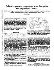
FIG. 2: (Color online) Proposed layouts for a twodimensional cluster state made of supercoherent qubits (SQs). Thick lines represent the always-on exchange interaction which exists between all pairs within a single SQ. These are modified to perform single LQ rotations. Thin lines represent exchange interactions between SQs which are turned on to perform coupling between the SQs. Two couplings are necessary. a) Two layer architecture with only top layer shown. Top layer consists of two of the four physical qubits (odd numbered) per SQ. The two even numbered physical qubits are placed directly beneath the odd numbered ones. Couplings exist between all pairs within a SQ. b) Four SQs on a two-dimensional lattice requiring two steps to cluster state creation. First, inter-SQ couplings are turned on between nearest horizontal SQs (solid lines). This creates a cluster state across each row of the lattice. Then a SWAP is applied between physical qubits at the ends of a diagonal within each SQ (for example 1 and 4) and the coupling is turned on between horizontal nearest neighbors (dashed lines). Another SWAP and single SQ z-rotations (done by intra-SQ coupling) complete the required inter-SQ evolution.
To create the cluster state we need to arrange the SQs in two-dimensions. This is complicated by the fact that only couplings between certain pairs of physical qubits lead to a diagonal coupling for the LQs. We suggest two designs which allow the appropriate qubits to be coupled. The first requires arranging dots in two layers. The top layer of such an architecture is shown in Fig. 2a and the second layer is placed directly underneath. Each SQ consists of two physical qubits on each layer with identical couplings between all physical qubits. An alternative is to arrange the SQs in a twodimensional lattice as in Fig. 2b. The Ising interaction between all SQs is done as follows. Assume that the singlet pairs are horizontal (1-2, 3-4). Then the vertical couplings between the SQs (3-9, 4-10) can be turned on to implement the Ising interaction (plus single SQ zrotations). We then apply a SWAP operation between dots on the diagonal of each SQ (1-4, 5-8). The SWAP is implemented by increasing the Heisenberg interaction between those qubits for a time t = π∆J where ∆J is the amount the coupling is changed from its original value. The singlets are now vertical (1-3, 2-4) and turning on the vertical couplings (2-5, 4-7) implements an Ising interaction between the horizontally arranged SQs. Another SWAP between physical qubits along the diagonal of the SQs completes the interactions. To summarize, encoding logical qubits into three and
4 four physical qubits allows for cluster state computation with only one species of quantum dot. These logical qubits are robust against a variety of decoherence mechanisms and allow for universal cluster state computation without using magnetic fields to manipulate qubits. The challenge is the arrangement of LQs in two dimensions and the ability to change the coupling strength between physical qubits. The three and four qubit encodings are powerful means of protecting quantum information against a variety of errors in both circuit model and cluster state quantum computation. We now present a basic examination of errors that may occur when cluster state computation is performed with these architectures and possible methods of correction. The three- and four-qubit encodings require equal couplings between multiple qubits. This is exceedingly difficult because the coupling strength depends exponentially on the spacing between the electrons [21]. For the fourqubit encoding the challenge is greater since one cannot put the dots at equal distances from each other in just two dimensions. Methods of dealing with this latter issue are given in [25]. The effect of having an unequal coupling in one of the LQs is a constant, linear, single-LQ rotation similar to the chemical shift term in liquid-state nuclear magnetic resonance (NMR) [23]. A possible error correcting technique is open-loop control or bang-bang operations [22]. As in NMR decoupling schemes, logical π-pulses can be applied to refocus unwanted evolution. A hardware approach is to digitize the interaction between qubits by enforcing minimum and maximum coupling strengths and a smooth transition between them. One method of achieving a maximum coupling is by moving electrons transversely in channels [21]. Another method is to use two ancilla quantum dots in an arrangement known as a quantum gate circuit (QGC) [24]. QGCs can provide a truly digital coupling, insuring zero coupling and a maximum value, thereby easing the process of making the couplings equal. Either of these hardware based designs allows for more control of the couplings between physical qubits easing the task of setting the different couplings to equal values, but require the addition of more dots per LQ. Inter-LQ couplings provide another possible source of errors. For both the three and four physical qubit encodings there is the problem of insuring the coupling is exactly zero when required. Achieving zero coupling can be done to some accuracy through electro-static gates and improved by bang-bang decoupling or via QGCs [24] which guarantee zero coupling. Inter-SQ evolution requires two adiabatic couplings between pairs of physical qubits. Errors that may occur include the ability to turn on the coupling simultaneously and the possibility that the coupling strengths are unequal. As SQ are immune to single physical qubit errors, having one of the couplings on will not effect the
state of the SQs. Thus, the task of turning the couplings on at the same time is only an issue during the ramp up when the couplings may be unequal. For unequal coupling strengths the one-SQ σz terms and the two-SQ σzj σzk terms depend linearly on the difference in coupling strengths. No other terms are introduced due to the inequality. This error can be corrected with LQ π-pulses or QGCs can be set up to help insure equal coupling. In conclusion, we have suggested several ways of achieving cluster state quantum computation using quantum dots. The architectures range from having one to four physical qubits per logical qubit. We have also analyzed possible errors for the three and four qubit encodings and suggested ways of fixing them. Which architecture is most practical depends on the particular physical implementation. The authors acknowledge support from the DARPA QuIST (MIPR 02 N699-00) program. Y.S.W. acknowledges support of the National Research Council through the Naval Research Laboratory. Computations were performed at the ASC DoD Major Shared Resource Center.
[1] R. Raussendorf and H.J. Briegel, Phys. Rev. Lett., 86, 5188, (2001). [2] R. Raussendorf, D.E. Browne, and H.J. Briegel, Phys. Rev. A, 68, 022312, (2003). [3] H.J. Briegel and R. Raussendorf, Phys. Rev. Lett., 86, 910, (2001). [4] M.A. Nielsen, Phys. Rev. Lett., 93, 040503, (2004). [5] D.E. Browne and T. Rudolph, quant-ph/0405157. [6] A-N. Zhang, C-Y. Lu, X-Q. Zhou, Y-A. Chen, Z. Zhao, T. Yang, and J-W. Pan, quant-ph/0501036. [7] P. Walther, et al, Nature, 434, 169, (2005). [8] O. Madel, M. Greiner, A. Widera, T. Rom, T.W. Hansch and I. Bloch, Nature, 425, 937, (2003). [9] A. Shabaev, Al. L. Efros, D. Gammon, and I. A. Merkulov, Phys. Rev. B, 68, 201305(R), (2003). [10] A.H. MacDonald, S.M. Girvin, and D. Yoshioka, Phys. Rev. B, 37, 9753, (1988); A. Mizel and D.A. Lidar, Phys. Rev. Lett., 92, 077903, (2004). [11] G. Burkard, H-A. Engel, and D. Loss, Fortschr. Phys., 48, 965, (2000). [12] J. Levy, Phys. Rev. Lett., 89, 147902, (2002). [13] S.C. Benjamin, Phys. Rev. A, 64, 054303, (2001). [14] E.M. Fortunato, L. Viola, J. Hodges, G. Teklemariam, and D.G. Cory, New J. Phys., 4, 5.1, (2002). [15] B.E. Kane, Nature (London), 393, 133, (1998). [16] Y.S. Weinstein and C.S. Hellberg, quant-ph/0408037. [17] D. Bacon, K.R. Brown, K.B. Whaley, Phys. Rev. Lett., 87, 247902, (2001). [18] D.P. DiVincenzo, D. Bacon, J. Kempe, G. Burkard, K.B. Whaley, Nature (London), 408, 339, (2000). [19] J. Schliemann, D. Loss, and A.H. MacDonald, Phys. Rev. B, 63, 085311. [20] A. Barenco, et al., Phys. Rev. A, 52, 3457, (1995). [21] M. Friesen, R. Joynt, and M.A. Eriksson, Appl. Phys. Lett., 81, 4619, (2002).
5 [22] L. Viola and S. Lloyd, Phys. Rev. A, 58, 2733, (1998); D. Vitali and P. Tombesi, Phys. Rev. A, 59, 4178, (1999). [23] D.G. Cory, M.D. Price, T.F. Havel, Physica D, 120, 82, (1998).
[24] C.S. Hellberg and Y.S. Weinstein, work in progress. [25] Y.S. Weinstein and C.S. Hellberg, work in progress.