6th International Conference on Electrical and Computer Engineering ICECE 2010, 18-20 December 2010, Dhaka, Bangladesh
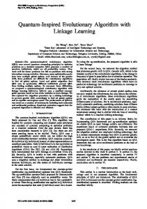
Quantum Evolutionary Algorithm Based Fast Speed Controlled Induction Motor Drive with CRTRL Flux Estimator Md. Habibullah1, Md. Amjad Hossain2, Md. Abdur Rafiq1, and B. C. Ghosh3 1
Department of Electrical and Electronic Engineering, 2Department of Computer Science and Engineering Khulna University of Engineering and Technology (KUET), Khulna, Bangladesh 3 Department of Electrical and Electronic Engineering American International University Bangladesh (AIUB), Dhaka, Bangladesh E-mail:
[email protected]
Abstract- This paper proposes the Quantum Evolutionary Algorithm (QEA) based fast speed response controller tuning for induction motor drive. Here the proportional and integral gains of PI controller are optimized by QEA to achieve quick speed response. A simple rotor flux estimator based on Correlated Real Time Recurrent Learning (CRTRL) algorithm is proposed for high performance induction motor drive. Simulation tests have been conducted to study the dynamic performances of the drive system for both the Conventional Genetic Algorithm (CGA) based PI and QEA based PI controllers. The proposed method shows better control performance than CGA based induction motor drive under transient and steady state conditions. IndexTerms- Quantum evolutionary algorithm, conventional genetic algorithm, correlated real time recurrent learning, fitness function, flux estimation.
I. INTRODUCTION The induction motors are widely used in various industries as work horse to produce rotational motion and force. Progress in the field of power electronics and microelectronics enables the application of induction motors for high performance drives, where traditionally only the DC motors were applied [1]. Induction motor drives with high performance control laws offer the similar control capabilities or even superior to that of separately excited DC motors [2]. A methodology to achieve this is by applying the field orientation control (FOC) [3]. Because of torque/flux decoupling in FOC it provides good dynamic response and accurate motion control compared to dc motors. Flux estimation is one of the important tasks in implementing high performance motor drives. Implementation of an integrator in voltage based method for motor flux estimation is no easy task for dc drift and initial value problems of the integrator. A new flux estimator based on CRTRL is introduced in [4] to overcome this problem. The Engineering community has shown a significant interest in optimization for many years [5]–[7]; in particular, there has been a focus on global optimization of numerical, real-valued problems for which exact and analytical methods do not function suitably. During the last few decades, a number of general-purpose optimization algorithms have been proposed for finding optimal solutions, some of which are; Evolution Strategies [8], Evolutionary programming [9], Genetic Algorithm (GA) [10], Particle Swarm Optimization (PSO) [11] and Differential Evolution (DE) [12]. These algorithms are also known as
978-1-4244-6279-7/10/$26.00 ©2010 IEEE
Evolutionary Algorithms (EAs) or Nature Inspired Algorithms because they follow simple rules of nature. These algorithms have also become popular because of their advantages over the traditional optimization techniques. The optimization performance of all the algorithms mentioned above degrades with a small population and can not optimize the solution within a very short time.
QEA is a novel probability optimization algorithm based on the concept and principles of quantum computing [13]. Compared with CGA, QEA has a better characteristic of diversity in the population and can keep the balance of exploration and exploitation more easily- even with a small population. So QEA has become a research hotpot in recent years. In a closed loop, speed control system, the speed error is processed through PI controllers. With the elapse of time, the error varies and full effectiveness of the control aspect cannot be achieved. Sometimes, the conventional controllers produce unwanted oscillations or slow response [14]. In this paper, PI controller constants adjusted by QEA is proposed to eliminate these problems and to achieve fast speed response. The QEA is implemented to have optimum performance with a desired fitness function. The control strategy used for the induction motor drive is field orientation control and is derived in rotor field coordinates. II. MATHEMATICAL MODEL Under the usual assumptions, the fifth order nonlinear state space model of induction motor is represented in the synchronous reference frame (d-q) by as follows [15]:
vds = (Rs + pLs )ids − ωe Ls iqs + pLm idr − ωe Lm iqr
(1)
vqs = ωe Ls ids + (Rs + pLs )iqs + ωe Lmidr + pLmiqr
(2)
0 = pLmids − ωsl Lmiqs + ( Rr + pLr )idr − ωsl Lr iqr
(3)
0 = ωsl Lm ids + pLm iqs + ( Rr + pLr )iqr + ωsl Lr idr
(4)
Te = Jp ω m + Bω m + TL
(5)
Where ωe , ω r and ω sl (= ω e − ω r ) are the synchronous, rotor
and slip angular speeds respectively and Lm is the mutual inductance and p is the differential operator.
478
The developed electromagnetic torque in terms of d- and qaxis variables is given by:
Te =
3 Pp Lm (iqs idr − ids iqr ) 2
(6)
Where, Pp is the number of pole pairs. If the field orientation is established such that d-axis is aligned along the rotor flux and is normally kept constant; qaxis rotor flux is set zero, and the following relations are obtained:
ψ r = ψ dr = L m i ds
(7)
ω sl = (1 / τ r )( i qs / i ds )
(8)
Where τ r (= Lr / Rr ) is the time constant of the rotor.
I qr = −( Lm / L r )i qs and i dr = 0
(9)
estimated torque and fluxes. In this paper, QEA is used to optimize the proportional gain ( k p ) and integral gain ( k i ) of PI controller. In Fig. 1 the proposed QEA control system is used to optimize the PI controller gains in the speed loop and the inverter operates in hysteresis current control mode. IV.
QUANTUM EVOLUTIONARY ALGORITHM
The QEA is a stochastic search and optimization method based on the principles of natural biological evolution such as the quantum bit and the superposition of states [13]. The QEA can treat the balance between exploration and exploitation more easily when compared with CGA. The evolution procedure of QEA is shown in fig. 2. Producing initial populations is the first step of QEA. The population is composed of the chromosomes that are represented by quantum bit or Q-bit which is the smallest unit of information in QEA. The corresponding evaluation of a population is called the “fitness function”. It is the performance index of a population. In this paper, the fitness function is defined as:
Fitness =
Considering equations (7-9) the torque equation (6) becomes
Te = (3 / 2) Pp ( Lm / Lr )ψ dr iqs
(10)
Hence, only q-axis stator current controls the developed electromagnetic torque if rotor flux is maintained constant. III. PROPOSED CONTROL SCHEME
* * Te = k p (ω m − ω m ) + k i ∫ (ω * − ω ) dt m m * * i = k p1Φ + k i1 ∫ Φdt , ω − ω = Φ ds m m
*
i qs = k p 2τ + k ∫ τdt i2
*
Te
,
− Te
ς = ∫ speed _ error dt * and speed_error = ω m − ω m .
is the objective function
A Q-bit may be in the “1” state, in the “0” state, or in any superposition of the two. Superposition of logical state can be
0 + β 1 ”. Another way of writing
“superposition” as a vector is shown below:
α 0 + β 1 ↔ ⎛⎜⎜ α ⎞⎟⎟ ⎝β ⎠
(11)
(12)
=τ
(14)
where,
expressed as “ α
In the proposed QEA controller the command torque and stator reference currents are generated as follows:
1 ς +1
(13)
A block diagram of the field orientation control method of induction motor drive is shown in Fig. 1. The estimated fluxes are obtained through CRTRL [4] and are used to generate the
The complex numbers α and β are called the “amplitudes” of the superposition. |αi|2gives the probability that the Q-bit will be found in “0” state and |βi|2gives the probability that the qubit will be found in “1” and they satisfy the normalization condition |αi|2 +|βi|2 = 1. A Q-bit is also defined with a pair of numbers (α, β) and a Q-bit individual as a string of m Q-bits is defined as [13]: A/C supply
Quantum Evolutionary Algorithm
ω m*
ψ r*
PI
+-
+
ψˆ r
Φ -
Te*
+
Tˆe PI1
-
τ
PI2
Iqs*
Ids*
(15)
Slip calculator & Reference voltage generator
Ias* Ibs*
θˆv
CRTRL Algorithm based Flux and Torque estimator
Current comparator & switching signal generator
θˆ
Current controlled inverter
θˆs
α-β abc
Ia Ib
bias ωm Fig. 1. Proposed Control Scheme
479
Speed Encoder
IM
⎡α 1 α 2 ... α m ⎤ q=⎢ ⎥ ⎣ β1 β 2 ... β m ⎦
(16)
Where |αi|2 +|βi|2 =1, i = 1, 2, 3…..m. A Q-gate defined as a mutation operator is applied on the Q-bit to update their probability amplitudes as follows:
where ϕ (⋅) is an activation function, and the (q+l+1)-by-1 weight vector Wi(k), which is connected to the ith neuron in the recurrent network, corresponds to the ith column of the transposed weight matrix W T(k) . The derivative matrix of the state vector x(k) with respect to the weight vector Wi : Λ i (k ) =
⎛ α ⎞ ⎡cos(Δθ i ) − sin( Δθ i )⎤⎛ α i ⎞ ⎜ ⎟=⎢ ⎜ ⎟ ⎜ β ' ⎟ sin( Δθ ) cos(Δθ ) ⎥⎜ β ⎟ i i ⎦⎝ i ⎠ ⎝ i⎠ ⎣ ' i
(17)
∂x (k ) ∂wi (k − 1) Z-1 I Z-1 I
Where Δθi, i=1, 2, 3…., m, is the rotation angle of a Q-bit towards the “0” state or “1” state depending on its sign. and
α
' 2 i
β
' i
must
+β
' 2 i
satisfy
the
normalization
(19)
W11
α i' iαs iβs
condition
ωr
bias
given interval of generations. Along with Q-bit population, a binary population is also maintained for evaluation process. In this paper, QEA is used to optimize the value of two gains k p
Ψ αr
Φ(.)
Ψ βr
W21
Δiαs Δiβs
= 1 . The crossover operator is employed after a
Φ(.)
W28
W18
Fig. 3. Rotor flux synthesis by proposed CRTRL algorithm based RNN
Rotor Flux Synthesis by CRTRL algorithm is shown in Fig. 3.
and k i .
VI. SIMULATION RESULTS
V. CRTRL ALGORITHM BASED FLUX ESTIMATOR The fully connected RNN consists of q neurons with l external inputs, as shown in Fig. 3. Let the q-by-1 vector x (k) denotes the state of the network in the form of a nonlinear discrete-time system, the (l + 1)-by-1 vector u (k) denotes the input (including bias) applied the network, and the p-by-1 vector y (k) denotes the output of the network. The process equation in the state-space description of the network is written in the following form [4]: (k ) z (k )⎤ ⎥ (k ) z (k )⎥ ⎥ # ⎥ ( k ) z ( k ) ⎦⎥
(18)
10 8
Kp
⎡ϕ (W 1T ⎢ ϕ (W 2T x ( k + 1) = ⎢⎢ ⎢ T ⎣⎢ϕ (W q
In order to show the improvement of the proposed PI controller constants adjusted by the QEA and the CGA for speed control of induction motor drive system, some simulation tests have been performed using both the controllers. The parameters of the induction motor are given below: 3φ, 1hp, 220V, 2 pairs of poles, 50 Hz, Rs=13.25Ω, Ls=Lr=0.8245, Rr=16.818Ω, Lm=0.80H, J=0.0075kg-m2, B=0.0008Nm-sec/rad.
QEA
6
CGA
4
b
2 0
Selection and global migration
B(t)
Selection
Local migration
b2 t
btw-x1 and b1t -1
Local Local migration migration
..
Selection
Observation
Q(t-1)
q1t -1
3
4
5
(a)
bnt btw-xnt and bnt -1
...
xnnt t
x
qnt -1
Update
0.20
CGA
0.008
Observation Q-gate
2
0.010
...
x1t
P(t)
t
1
T im e in s e c
Ki for QEA
b1t
0
0.15
0.006 0.10 0.004
QEA 0.05
0.002 0.000
Q-gate
0
1
2
3
4
5
Time in sec
(b)
Update
Fig. 4. Updating of two gains (a)
Fig. 2. Overall structure of QEA [13]
480
k p and (b) k i
0.00
Ki for CGA
Best Solution
The variation of two gains is given in Figs. 4(a) and 4(b) respectively. Fig. 4(a) shows that the value of k p varies within a band for CGA even under steady state condition where as it becomes a constant for the proposed QEA controller. This variation of k p in case of CGA is responsible for speed fluctuation under steady state condition. Fig. 5 shows the speed response of QEA and CGA based controllers for different reference speeds. For the proposed QEA controller, the speed of the motor reaches the reference value (125 rad/s) faster than that of CGA controller. Similar characteristic was shown when the reference speed was changed from 125 rad/s (1193.5 rpm) to 75 rad/s. The faster speed response would be clear from Fig. 6 which is the small 1250
Speed in rpm
1000 750 CGA QEA R e fe re n c e
500 250 0
0
1
2
3
4
Load was suddenly increased from 0 Nm to 5 Nm at t=6 sec and shown in Fig. 7. It is observed that sudden application of load torque causes a very small dip in the speed curve for the proposed method. On the other hand, the CGA based PI controller system shows a larger dip and speed oscillation. VII. CONCLUSIONS In this paper, a quantum evolutionary algorithm based PI controller has been used to replace the conventional genetic algorithm based PI controller of induction motor drive system. To improve the performance of rotor flux estimator, a CRTRL algorithm based RNN is employed. It can be concluded that the proposed QEA based PI controller need less time to speed up the motor at transient condition and generate negligible speed fluctuation at rated speed under steady state condition. The proposed QEA based controller is capable to drive the load smoothly and shows better performance in load disturbance condition. The performance of the controller amazing and future research industrial applications will find optimization through QEA. REFERENCES
5
T im e in s e c
Fig. 5. Speed response of QEA and CGA based PI controller
scale representation of Fig. 5 into two parts, one is transient condition and the other is steady state condition. From Fig. 6(a), it can be seen that settling time for CGA based PI controller is 0.49 sec. whereas that of proposed QEA based PI controller is 0.41 sec. when reference speed was chosen 125 rad/s. Fig. 6(b) shows the speed response fluctuation at steady state condition in case of CGA controller whereas that of proposed QEA controller is almost constant. 1195
1250
0.41 sec
CGA
QEA
Speed in rpm
Speed in rpm
1000
Reference
0.49 sec
750 CGA QEA Reference
500
1190 CGA QEA Reference
1185
250 0 0.0
0.2
0.4
0.6
0.8
1180 1.0
1.0
1.5
Time in sec
2.0
2.5
3.0
Time in sec
(a)
(b)
1200
1200
1000
1000 Speed in rpm
Speed in rpm
Fig. 6. Zoomed Speed response of QEA and CGA based PI controller at (a) Transient condition for the time 0 to 1sec. (b) Steady state condition for the time 1 sec. to 3 sec. of Fig. 5.
800 600 400 200 0
800 600 400 200
0
2
4
6
Time in sec
8
10
0
0
2
4
6
8
10
Time in sec
(a) (b) Fig. 7. Speed response of (a) CGA controller (b) Proposed QEA controller with sudden load change
[1] C.M. Liaw, Y.S. Kung and C.M. Wa, “Design And Implementation Of A High Performance Field-Oriented Induction Motor Drive”, IEEE. Trans. Ind. Electron., Vol. 38, no. 4, pp. 275-282, 1991. [2] W. Leaonard, Control of Electrical Drives., New York: Springer Verlag, 1985. [3] J. Zhang, V. Thiagarajan, T. Grant and T.H. Barton, “New Approach to Field Orientation Control of a CSI Induction Motor Drive”, electric power applications. IEE Proc. B, vol. 135, no. 1, pp. 1-7, 1988. [4] Md. Abdur Rafiq, Naruttam Kumar Roy and B.C. Ghosh, “An Improved Induction Motor Rotor Flux Estimator Based on Correlated Real Time Recurrent Learning Algorithm”, Proc. Of international conferencepasco, Andhra University, Visakhapatnam, Ap, India, March 2008. [5] G. D. H. Kim, “GA-PSO Based Vector Control of Indirect Three Phase Induction Motor”, Applied Soft Computing, vol. 7, pp. 601-611, 2006. [6] B. Pryymak, et al., “Neural Network Based Flux Optimization Using a Model of Losses in Induction Motor Drives”, Mathematics and computers in simulation, vol. 71, pp. 290-298, 2006. [7] S. Ghozzi, K. Jelassi and X. Roboam, “Energy Optimization of Induction Motor Drives”, IEEE conference on Industrial Technology (ICIT), pp. 602-610, 2004. [8] I. Rechenberg, “Evolution Strategy: Optimization of Technical Systems by Means of Biological Evolution”, Fromman-Holzboog, 1973. [9] L. J. Fogel, A. J. Owens and M. J. Walsh, “Artificial Intelligence through a Simulation of Evolution”, In M. Maxfield, A. Callahan And L. J. Fogel, Editors, Biophysics And Cybernetic Systems. Proc. of the 2nd Cybernetic Sciences Symposium, pp. 131 – 155, Spartan Books, 1965. [10] J. H. Holland, “Adaptation in Natural and Artificial Systems: An Introductory Analysis with Applications to Biology, Control, and Artificial Intelligence”, Ann Arbor, MI: University of Michigan Press. [11] J. Kennedy and R. Eberhart, “Particle Swarm Optimization”, IEEE International Conference on Neural Networks (Perth, Australia), IEEE Service Center, Piscataway, NJ, pp. IV: 1942-1948, 1995. [12] R. Storn and K. Price, “Differential Evolution–A Simple and Efficient Adaptive Scheme for Global Optimization Over Continuous Spaces”, Tech. Rep, International Computer Science Institute, Berkley, 1995. [13] Kuk-Hyun Han and Jong-Hwan Kim, “Quantum-Inspired Evolutionary Algorithm for a Class of Combinatorial Optimization”, IEEE Trans. On Evolutionary Computation, vol. 6, no. 6, Dec. 2002. [14] M.A. Rafiq, M. Datta, M.G. Sarwer and B.C. Ghosh "A New Scheme for Field-Orientation Control of Induction Motor Drive with Adaptive Neural Flux Estimator," in Proc. IEEE PEDS-2005, Kuala Lumpur, Malaysia, pp 704-709, 28 Nov - 1 Dec, 2005. [15] B.C.Ghosh, “Parameter Adaptive vector controlled for CSI-fed Induction Motor Drive and Generalized Approaches for Simulation of CSI-IM System ”, P.hD. Thesis Department of Electrical Engineering, IIT, Kharagpur, July, 1992.
481