II Introduction for VHDL Users. This tutorial presents an introduction to the
Quartus® II software. It gives a general overview of a typical CAD flow for
designing ...
Quartus® II Introduction for VHDL Users This tutorial presents an introduction to the Quartus® II software. It gives a general overview of a typical CAD flow for designing circuits that are implemented by using FPGA devices, and shows how this flow is realized in the Quartus® II software. The design process is illustrated by giving step-by-step instructions for using the Quartus® II software to implement a simple circuit in an Altera® FPGA device. The Quartus® II system includes full support for all of the popular methods of entering a description of the desired circuit into a CAD system. This tutorial makes use of the VHDL design entry method, in which the user specifies the desired circuit in the VHDL hardware description language. Another version of this tutorial is available that uses Verilog hardware description language. The screen captures in the tutorial were obtained using Quartus® II version 11.0; if other versions of the software are used, some of the images may be slightly different.
Contents: Getting Started Starting a New Project Design Entry Using VHDL Code Compiling the VHDL Code Using the RTL Viewer Specifying Timing Constraints Quartus® II Windows
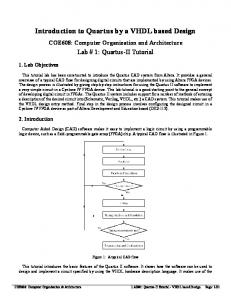
Computer Aided Design (CAD) software makes it easy to implement a desired logic circuit by using a programmable logic device, such as a field-programmable gate array (FPGA) chip. A typical FPGA CAD flow is illustrated in Figure 1.
Figure 1: Typical CAD flow.
It involves the following basic steps: • Design Entry – the desired circuit is specified either by using a hardware description language, such as Verilog or VHDL, or by means of a schematic diagram • Synthesis – the CAD Synthesis tool synthesizes the circuit into a netlist that gives the logic elements (LEs) needed to realize the circuit and the connections between the LEs • Functional Simulation – the synthesized circuit is tested to verify its functional correctness; the simulation does not take into account any timing issues • Fitting – the CAD Fitter tool determines the placement of the LEs defined in the netlist into the LEs in an actual FPGA chip; it also chooses routing wires in the chip to make the required connections between specific LEs • Timing Analysis – propagation delays along the various paths in the fitted circuit are analyzed to provide an indication of the expected performance of the circuit
A LTERA® C ORPORATION A PRIL 2011
2 Q UARTUS® II I NTRODUCTION FOR VHDL U SERS
• Timing Simulation – the fitted circuit is tested to verify both its functional correctness and timing • Programming and Configuration – the designed circuit is implemented in a physical FPGA chip by programming the configuration switches that configure the LEs and establish the required wiring connections This tutorial introduces the basic features of the Quartus® II software. It shows how the software can be used to design and implement a circuit specified using the VHDL hardware description language. It makes use of the graphical user interface to invoke the Quartus® II commands. During this tutorial, the reader will learn about: • Creating a project • Synthesizing a circuit from VHDL code using the Quartus® II Integrated Synthesis tool • Fitting a synthesized circuit into an Altera® FPGA • Examining the report on the results of fitting and timing analysis • Examining the synthesized circuit in the form of a schematic diagram generated by the RTL Viewer tool • Making simple timing assignments in the Quartus® II software
A LTERA® C ORPORATION A PRIL 2011
3 Q UARTUS® II I NTRODUCTION FOR VHDL U SERS
1
1
GETTING STARTED
Getting Started
Each logic circuit, or subcircuit, being designed with the Quartus® II software is called a project. The software works on one project at a time and keeps all information for that project in a single directory (folder) in the file system. To begin a new logic circuit design, the first step is to create a directory to hold its files. To hold the design files for this tutorial, we will use a directory called quartus_tutorial. The running example for this tutorial is a simple adder/subtractor circuit, which is defined in the VHDL hardware description language. Start the Quartus® II software. You should see a display similar to the one in Figure 2. This display consists of several windows that provide access to all the features of the Quartus® II software, which the user selects with the computer mouse. Most of the commands provided by the Quartus® II software can be accessed by using a set of menus that are located below the title bar. For example, in Figure 2 clicking the left mouse button on the menu named File opens the menu shown in Figure 3. Clicking the left mouse button on the entry Exit exits from the Quartus® II software. In general, whenever the mouse is used to select something, the left button is used. Hence we will not normally specify which button to press. In the few cases when it is necessary to use the right mouse button, it will be specified explicitly. For some commands it is necessary to access two or more menus in sequence. We use the convention Menu1 > Menu2 > Item to indicate that to select the desired command the user should first click the left mouse button on Menu1, then within this menu click on Menu2, and then within Menu2 click on Item. For example, File > Exit uses the mouse to exit from the system. Many commands can be invoked by clicking on an icon displayed in one of the toolbars. To see the list of available toolbars, select Tools > Customize > Toolbars. Once a toolbar is opened, it can be moved using the mouse. To see the command associated with an icon, position the mouse over the icon and a tooltip will appear that displays the command name. It is possible to modify the appearance of the display in Figure 2 in many ways. Section 7 shows how to move, resize, close, and open windows within the main Quartus® II display.
Figure 2: The main Quartus® II display.
A LTERA® C ORPORATION A PRIL 2011
4 Q UARTUS® II I NTRODUCTION FOR VHDL U SERS
1.1
Quartus® II Online Help
1
GETTING STARTED
Figure 3: An example of the File menu.
1.1
Quartus® II Online Help
The Quartus® II software provides comprehensive online documentation that answers many of the questions that may arise when using the software. The documentation is accessed from the menu in the Help window. To get some idea of the extent of documentation provided, it is worthwhile for the reader to browse through the Help menu. The user can quickly search through the Help topics by selecting Help > Search, which opens a dialog box into which keywords can be entered. Another method, context-sensitive help, is provided for quickly finding documentation about specific topics. While using most applications, pressing the F1 function key on the keyboard opens a Help display that shows the commands available for the application.
A LTERA® C ORPORATION A PRIL 2011
5 Q UARTUS® II I NTRODUCTION FOR VHDL U SERS
2
2
STARTING A NEW PROJECT
Starting a New Project
To start working on a new design we first have to define a new design project. The Quartus® II software makes the designer’s task easy by providing support in the form of a wizard. 1. Select File > New Project Wizard to reach a window that indicates the capability of this wizard. Press Next. This will bring up the wizard screen as shown in Figure 4.
Figure 4: Creation of a new project. 2. Set the working directory to be quartus_tutorial; of course, you can use a directory name of your choice. The project must have a name, which is usually the same as the top-level design entity that will be included in the project. Choose addersubtractor as the name for both the project and the top-level entity, as shown in Figure 4. Press Next. Since we have not yet created the directory quartus_tutorial, the Quartus® II software displays the pop-up box in Figure 5 asking if it should create the desired directory. Click Yes, which leads to the window in Figure 6.
Figure 5: The Quartus® II software can create a new directory for the project.
A LTERA® C ORPORATION A PRIL 2011
6 Q UARTUS® II I NTRODUCTION FOR VHDL U SERS
2
STARTING A NEW PROJECT
Figure 6: The wizard can include user-specified design files. 3. This window makes it easy to specify which existing files (if any) should be included in the project. Assuming that we do not have any existing files, click Next, which leads to the window in Figure 7.
A LTERA® C ORPORATION A PRIL 2011
7 Q UARTUS® II I NTRODUCTION FOR VHDL U SERS
2
STARTING A NEW PROJECT
Figure 7: Choose the device family and a specific device. 4. In this window, we can specify the type of device in which the designed circuit will be implemented. Choose the Stratix III® menu item as the target device family. We can let the Quartus® II software select a specific device in the family, or we can choose the device explicitly. We will take the latter approach. From the list of available devices, choose the device called EP3SE50F484C2. Press Next, which opens the window in Figure 8.
A LTERA® C ORPORATION A PRIL 2011
8 Q UARTUS® II I NTRODUCTION FOR VHDL U SERS
2
STARTING A NEW PROJECT
Figure 8: Other EDA tools can be specified. 5. In this window we can specify any third-party tools that should be used. A commonly used term for CAD software for electronic circuits is EDA tools, where the acronym stands for Electronic Design Automation. This term is used in the Quartus® II messages that refer to third-party tools, which are the tools developed and marketed by companies other than Altera® ; other tutorials show how such tools may be used. Since we will rely solely on the Quartus® II tools, we will not choose any other tools. Press Next. Now, a summary of the chosen settings appears in the screen shown in Figure 9. Press Finish, which returns to the main Quartus® II display. Note that addersubtractor is now specified as the current project, as indicated in the title bar at the top of the display. The screen should look similar to that of Figure 10.
A LTERA® C ORPORATION A PRIL 2011
9 Q UARTUS® II I NTRODUCTION FOR VHDL U SERS
2
STARTING A NEW PROJECT
Figure 9: Summary of the project settings.
Figure 10: The Quartus® II display for the created project.
A LTERA® C ORPORATION A PRIL 2011
10 Q UARTUS® II I NTRODUCTION FOR VHDL U SERS
3
3
DESIGN ENTRY USING VHDL CODE
Design Entry Using VHDL Code
As a design example, we will use the adder/subtractor circuit shown in Figure 11. The circuit can add, subtract, and accumulate n-bit numbers using the 2’s complement number representation. The two primary inputs are numbers A = an−1 an−2 · · · a0 and B = bn−1 bn−2 · · · b0 , and the primary output is Z = zn−1 zn−2 · · · z0 . Another input is the AddSub control signal which causes Z = A + B to be performed when AddSub = 0 and Z = A − B when AddSub = 1. A second control input, Sel, is used to select the accumulator mode of operation. If Sel = 0, the operation Z = A ± B is performed, but if Sel = 1, then B is added to or subtracted from the current value of Z. If the addition or subtraction operations result in arithmetic overflow, an output signal, Overflow, is asserted. To make it easier to deal with asynchronous input signals, we will load them into flip-flops on a positive edge of the clock. Thus, inputs A and B will be loaded into registers Areg and Breg, while Sel and AddSub will be loaded into flip-flops SelR and AddSubR, respectively. The adder/subtractor circuit places the result into register Zreg.
Figure 11: The adder/subtractor circuit. The required circuit is described by the VHDL code in Figure 12. For our example, we will use a 16-bit circuit as specified by n = 16.
A LTERA® C ORPORATION A PRIL 2011
11 Q UARTUS® II I NTRODUCTION FOR VHDL U SERS
3
DESIGN ENTRY USING VHDL CODE
LIBRARY ieee ; USE ieee.std_logic_1164.all ; -- Top-level entity ENTITY addersubtractor IS GENERIC ( n : INTEGER := 16 ) ; PORT ( A, B Clock, Reset, Sel, AddSub Z Overflow END addersubtractor ;
: : : :
IN STD_LOGIC_VECTOR(n-1 DOWNTO 0) ; IN STD_LOGIC ; BUFFER STD_LOGIC_VECTOR(n-1 DOWNTO 0) ; OUT STD_LOGIC ) ;
ARCHITECTURE Behavior OF addersubtractor IS SIGNAL G, H, M, Areg, Breg, Zreg, AddSubR_n : STD_LOGIC_VECTOR(n-1 DOWNTO 0) ; SIGNAL SelR, AddSubR, carryout, over_flow : STD_LOGIC ; COMPONENT mux2to1 GENERIC ( k : INTEGER := 8 ) ; PORT ( V, W : IN STD_LOGIC_VECTOR(k-1 DOWNTO 0) ; Sel : IN STD_LOGIC ; F : OUT STD_LOGIC_VECTOR(k-1 DOWNTO 0) ) ; END COMPONENT ; COMPONENT adderk GENERIC ( k : INTEGER := 8 ) ; PORT ( carryin : IN STD_LOGIC ; X, Y : IN STD_LOGIC_VECTOR(k-1 DOWNTO 0) ; S : OUT STD_LOGIC_VECTOR(k-1 DOWNTO 0) ; carryout : OUT STD_LOGIC ) ; END COMPONENT ; BEGIN PROCESS ( Reset, Clock ) BEGIN IF Reset = '1' THEN Areg '0'); Breg '0'); Zreg '0'); SelR