rate but requiring only moderate decoding complexity are desirable. ... In this paper, we focus on a new class of QO-STBC whose ML decoding only requires the.
Quasi-Orthogonal STBC with Minimum Decoding Complexity Chau Yuen, Yong Liang Guan, Tjeng Thiang Tjhung
Abstract — In this paper, we consider a Quasi-Orthogonal STBC with minimum decoding complexity (MDC-QOSTBC). We formulate its algebraic structure and propose a systematic method for its construction. We show that a maximum likelihood (ML) decoder for this MDCQOSTBC for any numbers of transmit antennas only requires the joint detection of two real symbols. Assuming the use of a square or rectangular QAM or MPSK modulation for this MDCQOSTBC, we also obtain the optimum constellation rotation angle in order to achieve full diversity and optimum coding gain. We show that the maximum achievable code rate of these MDC-QOSTBC is 1 for three and four antennas, and ¾ for five to eight antennas. We also show that the proposed MDC-QOSTBC has several desirable properties, such as more even power distribution among antennas and better scalability in adjusting the number of transmit antennas compared with the Co-ordinate Interleaved Orthogonal Design (CIOD) and Asymmetric CIOD codes. For the case of an odd number of transmit antennas, MDC-QOSTBC also has better decoding performance than CIOD.
Index Terms — Minimum Decoding Complexity, Quasi-Orthogonal Space-Time Block Code, Quasi-Orthogonality Constraints.
I.
INTRODUCTION
Orthogonal Space-Time Block Code (O-STBC) that can offer full transmit diversity and linear decoding complexity has been designed in [1,2,12]. Unfortunately, O-STBCs suffer from a reduced code rate when complex signal constellations and more than two transmit antennas are used [1,2,12]. Therefore STBC designs that can achieve full transmit diversity and higher code
rate but requiring only moderate decoding complexity are desirable. To this end, some Quasi-Orthogonal STBC (QO-STBC) with constellation rotation has been proposed in [3-6] that is able to achieve full code rate by relaxing the strict orthogonality requirement of O-STBC. The maximum-likelihood (ML) decoding of QO-STBC can be performed by searching over only pairs, instead of the full set, of the possible transmitted complex symbols. Subsequently, Coordinate Interleaved Orthogonal Design (CIOD) and Asymmetric CIOD (ACIOD) have been proposed in [7,8] to provide high code rate and full transmit diversity (after constellation rotation) with even lower decoding complexity. However, these codes require up to half of the transmit antennas to be turned off regularly, thus introducing high peak-to-average transmitter power ratio which is undesirable [8,11]. In this paper, we focus on a new class of QO-STBC whose ML decoding only requires the joint detection of two real symbols. This is the lowest possible decoding complexity for any nonorthogonal STBCs. Hence we call it Minimum-Decoding-Complexity QO-STBC (MDCQOSTBC). We shall derive its algebraic structure, propose systematic methods to construct it, and investigate its maximum achievable code rate. We will also compare its decoding performance, power distribution properties (which is related to the number of antennas to be turned off regularly) and antenna scalability (scalability in supporting different number of transmit antennas) with the existing QO-STBCs, CIOD and ACIOD.
II.
A.
SIGNAL MODEL AND O-STBC
Generic STBC
Suppose that a generic STBC codeword is transmitted from Nt transmit antennas to Nr receive antennas over an interval of T symbol periods in which the propagation channel condition is time-invariant and known to the receiver. The transmitted codeword can be written as a T × Nt matrix G that consists of K arbitrary complex constellation symbols. Its code rate is defined as 2
R = K/T. Following the model in [9], G can be expressed as: G = ∑ q =1 ( xqR A q + jxqI B q ) K
(1)
where the transmitted symbols are xq = xqR + jxqI , and the superscripts ( )R and ( )I denote respectively, the real and imaginary part of a complex element, vector or matrix. Matrices Aq and Bq are called the “dispersion matrices” and are of size T × Nt. For the given numbers of transmit antennas, the design of a STBC depends crucially on the choices of the parameters T, K, and the dispersion matrices {Aq, Bq}. The transmitted and received signals are related by [9]: r� = ρ N t Hx� + η�
(2)
⎡ r1R ⎤ ⎡ η1R ⎤ ⎡ x1R ⎤ ⎢ I⎥ ⎢ I⎥ ⎢ I⎥ ⎡ A1h1 ⎢ r1 ⎥ ⎢ η1 ⎥ ⎢ x1 ⎥ ⎢ where r� = ⎢ # ⎥ , x� = ⎢ # ⎥ , η� = ⎢ # ⎥ , H = ⎢ # ⎢ R⎥ ⎢ R ⎥ ⎢ R⎥ ⎢A1h N ⎢rNr ⎥ ⎢ ηNr ⎥ ⎣ r ⎢ xK ⎥ I ⎥ I ⎥ ⎢r I ⎥ ⎢ ⎢ η ⎣ xK ⎦ ⎣ Nr ⎦ ⎣ Nr ⎦
⎡ A Rq Aq = ⎢ I ⎢⎣ A q
⎡ −B Iq − A Iq ⎤ ⎥ , Bq = ⎢ R A qR ⎥⎦ ⎢⎣ B q
B1h1
...
AK h1
# B1h Nr
% # ... AK h Nr
BK h1 ⎤ ⎥ # ⎥, BK h Nr ⎥⎦
−B Rq ⎤ ⎡hiR ⎤ ⎥ ,h i = ⎢ I ⎥ . −B qI ⎥⎦ ⎣ hi ⎦
In the above equation, ri and ηi (1 ≤ i ≤ Nr) are T × 1 column vectors which contain the received signal and AWGN noise for the ith receive antenna respectively, over T symbol periods. H is called the equivalent channel matrix, hi is Nt × 1 column vector that contains the fading coefficients of the spatial sub-channels between the Nt transmit antennas and ith receive antenna. The normalization factor
ρ / Nt in (2) ensures that ρ is the signal-to-noise ratio (SNR) at each
receive antenna, regardless of whatever Nt is.
B.
Orthogonal STBC
Orthogonal STBC (O-STBC) has the simplest decoding complexity, as its ML decoding can be achieved by linear detection. It has been shown in [2] that to design an O-STBC is equivalent to finding K sets of dispersion matrices {Aq, Bq} (in this paper the underlined dispersion matrices 3
are meant for an O-STBC, while the dispersion matrices of the MDC-STBC’s are not underlined), which satisfy: (i) A Hq A q = I Nt
, B Hq B q = I Nt
(ii) A Hq A p = − A Hp A q , B Hq B p = −B Hp B q (iii)A Hq B p = B Hp A q
III.
1≤ q ≤ K 1≤ q ≠ p ≤ K
(3)
1 ≤ q, p ≤ K
ALGEBRAIC STRUCTURE OF MDC-QOSTBC
In MDC-QOSTBC, the goal is to divide the transmitted symbols into K independent groups (K = number of complex symbols transmitted in one block), such that every complex symbol is orthogonal to all other complex symbols, but the I and Q components within the same complex symbol need not be orthogonal. As a result of such grouping, the received symbols can be separated into K independent groups by simple linear processing or matched filtering, ML decoding of different groups can then be performed separately, and in parallel. In each group, only two real symbols (i.e. the I and Q components) need to be jointly detected. Definition 1: A Minimum-Decoding-Complexity QO-STBC (MDC-QOSTBC) is a QO-STBC
such that its equivalent channel matrix H has the property that HTH is block-diagonal with nonzero sub-matrices of size 2×2. It should be noted from Definition 1 that the HTH of an O-STBC [1,2,12] is a diagonal matrix, while the HTH of a QO-STBC which needs the joint detection of s real symbols will be blockdiagonal with s×s sub-block matrices. Therefore, MDC-QOSTBC has the minimum decoding complexity among all non-orthogonal STBC, because it only needs the joint detection of two real symbols, anything less complex (i.e. linear detection of only one real symbol) would be an OSTBC. Next we derive the algebraic structure of MDC-QOSTBC. At the receiver, a matched filter HT is multiplied to the received signal r� in (2) to separate the received symbols into K independent groups. Let us consider a snapshot of HTH as follows: 4
⎡ # ⎢h T A T ⎢ 1 q ⎢ h1T BqT T H H=⎢ T T ⎢h1 A p ⎢ h1T BpT ⎢ ⎢⎣ #
" " " " " "
# ⎤ AqT ⎥⎥ ⎡" Aq h1 Bq h1 A p h1 Bp h1 "⎤ BqT ⎥ ⎢ ⎥ # # # # # #⎥ T⎥⎢ Ap ⎥ ⎢" Aq h N Bq h N A p h N Bp h N "⎥ r r r r ⎦ BpT ⎥ ⎣ ⎥ # ⎥⎦
T Nr T Nr T Nr T Nr
h h h h
" ⎡" ⎢ NR T T ⎢# ∑ i =1 hi ( Aq Aq ) hi ⎢ NR T T ⎢# ∑ i =1 hi ( Bq Aq ) hi =⎢ ⎢# ∑ N R hiT ( A pT Aq ) hi i =1 ⎢ NR T ⎢# h B T Aq ) hi ∑ i =1 i ( p ⎢ ⎢⎣" "
"
∑ ∑ ∑ ∑
NR
i =1
"
hiT ( AqT Bq ) hi
NR
i =1 NR
i =1
∑ h (B B ) h ∑ h (A B ) h ∑ h (B B ) h ∑
NR
i =1
T i
T q
NR
i =1
hiT ( AqT A p ) hi
NR
q
i =1
i
hiT ( BqT A p ) hi
NR
T i
T p
q
i
i =1
T i
T p
q
i
i =1
"
NR
hiT ( A pT A p ) hi hiT ( BpT A p ) hi "
1≤ q ≠ p ≤ K
"⎤ ⎥ ∑ i =1 hiT ( AqTBp ) hi # ⎥ ⎥ N ∑ i=R1 hiT ( BqTBp ) hi # ⎥ ⎥ (4) NR T T ∑ i =1 hi ( A p Bp ) hi # ⎥⎥ N ∑ i =R1 hiT ( BpTBp ) hi # ⎥⎥ " "⎥⎦ "
NR
To comply with Definition 1, the boxed summation terms in (4) must all be zero. To achieve this, AqT A p , AqT Bp , BqT A p , BqT Bp must be skew-symmetric, as a result of Theorem 1 stated below.
Theorem 1: For any vector v, vTMv = 0 if the matrix M is skew-symmetric, i.e. MT = –M.
Proof of Theorem 1: Let vTMv = c. Since c is a constant value, cT = c = vTMTv = –vTMv (if MT = –M). Now, c + cT = vTMv – vTMv = 0, so c = 0, hence Theorem 1 is proved.
■
Theorem 2: For different complex symbols (indexed using subscripts q and p) in an MDC-STBC
to be orthogonal to each other, i.e. AqT A p , AqT Bp , BqT A p , BqT Bp to be skew-symmetric, their dispersion matrices {Aq, Bq} and {Ap, Bp} must possess the following algebraic structure, herein referred as Minimum Decoding Complexity Quasi-Orthogonality (MDC-QO) Constraints: (i) A Hq A p = − A Hp A q , B Hq B p = −B Hp B q (ii)A Hq B p = B Hp A q
1≤ q ≠ p ≤ K
(5)
Proof of Theorem 2: We take the MDC-QO Constraints (5)(i) as an example:
5
A Hq A p = − A Hp A q ⇒ ( A Rq + jA Iq ) H ( A Rp + jA Ip ) = −( A Rp + jA Ip ) H ( A Rq + jA Iq ) ⎧ ( A R )T A R + ( A I )T A I = − ( A R )T A R − ( A I )T A I (real part) p q p p q p q ⎪ q ⇒⎨ T T T T ⎪( A qR ) A Ip − ( A qI ) A Rp = − ( A Rp ) A qI + ( A Ip ) A qR (imag part) ⎩ A skew-symmetric matrix M and a symmetric matrix N can then be defined as follows:
⎧M = ( A R ) T A R + ( A I )T A I q p q p ⎪ ⇒⎨ T T ⎪ N = ( A Rq ) A Ip − ( A Iq ) A Rp ⎩
(Skew-symmetric) (Symmetric)
⎡M −N ⎤ T One can show that AqT A p = ⎢ ⎥ , hence (5)(i) ensures that Aq Ap is skew-symmetric. N M ⎣ ⎦ Similarly AqT Bp , BqT A p , BqT Bp can be proven to be skew-symmetric as long as MDC-QO Constraints in (5) are fulfilled. Hence Theorem 2 is proved.
■
Note that the difference between the properties of O-STBC in (3) and MDC-QO Constraints in (5) is that (3)(iii) holds for all k and p, whereas (5)(iii) holds only when k ≠ p. In addition, the condition (3)(i) is not required for the MDC-QO constraint because it affects the diversity order and not the decoding complexity. It can be easily verified that all the CIOD and ACIOD codes from [7,8] comply with the algebraic structure stated in Theorem 2, although they were not designed from this approach. This shows that our proposed MDC-QO Constraints are generic and inclusive.
IV.
A.
MDC-QOSTBC
Construction of MDC-QOSTBC from O-STBC
In this section, we propose a systematic method to construct an MDC-QOSTBC from an OSTBC. The proposed method consists of four mapping rules, as listed in Theorem 3 below, to
6
map the dispersion matrices of an O-STBC to the dispersion matrices of an MDC-QOSTBC. Theorem 3: Consider an O-STBC with code length T for Nt transmit antennas, which consists of K sets of dispersion matrices denoted as {Aq, Bq}, 1 ≤ q ≤ K. An MDC-QOSTBC with code
length 2T for 2Nt transmit antennas, which consists of 2K sets of dispersion matrices denoted as {Aq, Bq}, where 1 ≤ q≤ 2K, can be constructed with the following four mapping rules: ⎡Aq Rule 1: A q = ⎢ ⎣0
0 ⎤ ; A q ⎥⎦
⎡ jB q Rule 3: A K + q = ⎢ ⎣ 0
0 ⎤ ; jB q ⎥⎦ 1≤ q ≤ K
⎡ 0 Rule 2: B q = ⎢ ⎣ jA q
jA q ⎤ ; 0 ⎥⎦
⎡0 Rule 4: B K + q = ⎢ ⎣B q
(6)
Bq ⎤ . 0 ⎥⎦
Proof of Theorem 3: Based on the structure of the O-STBC’s dispersion matrices {Aq, Bq} specified in (3), it can be proven that the mapping rules in (6) result in a new set of dispersion matrices {Aq, Bq} that satisfy the MDC-QO Constraints in (5). Hence an MDC-QOSTBC can be constructed accordingly. The detailed proof is omitted, as the verifications are routine.
■
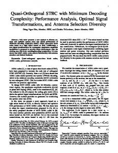
A graphical example to illustrate the construction of an MDC-QOSTBC for four transmit antennas from the Alamouti O-STBC for two transmit antennas [1] is shown in Figure 1, where A1, A2, B1, B2 denote the dispersion matrices of the Alamouti O-STBC, while A1 to A4, B1 to B4 denote the dispersion matrices of the newly constructed MDC-QOSTBC. The codeword G of the resultant MDC-QOSTBC is shown in (7). It can be shown that its ML decoding metric can be calculated as the sum f1 + f2 + f3 + f4, where the terms f1 to f4 are given in (8). Since each fi is just a function of xiR and xiI for 1 ≤ i ≤ 4 (i.e. joint detection of two real symbols), and is independent of xk for i ≠ k, the minimization of the ML metric is equivalent to minimizing the four fi terms
independently. This implies a lower decoding complexity as compared to the existing QOSTBCs [3-6].
7
⎡ x1R + jx3R ⎢ R − x2 + jx4R ⎢ G= ⎢ − x1I + jx3I ⎢ I I ⎢⎣ x2 + jx4
x2R + jx4R x1R − jx3R − x2I + jx4I
− x1I + jx3I x2I + jx4I x1R + jx3R
− x1I − jx3I
− x2R + jx4R
− x2I + jx4I ⎤ ⎥ − x1I − jx3I ⎥ x2R + jx4R ⎥ ⎥ x1R − jx3R ⎥⎦
(7)
2 2 2 4 N f1 ( x1 ) = ∑ r =r1 ⎡⎢(∑ n =1 hn ,r )( x1R + x1I ) + 2 Re { x1R (α ) − x1I ( β ) − x1R x1I (γ )}⎤⎥ ⎣ ⎦ 2 2 2 4 N f 2 ( x2 ) = ∑ r =r1 ⎡⎢(∑ n =1 hn ,r )( x2R + x2I ) + 2 Re { x2R ( χ ) − x2I (δ ) − x2R x2I (ϕ )}⎤⎥ ⎣ ⎦ 2 2 2 4 N f3 ( x3 ) = ∑ r =r1 ⎡⎢ (∑ n =1 hn ,r )( x3R + x3I ) + 2 Re { jx3R (α ) + jx3I ( β ) + x3R x3I (γ )}⎤⎥ ⎦ ⎣ 2 2 2 4 N f 4 ( x4 ) = ∑ r =r1 ⎡⎢(∑ n =1 hn ,r )( x4R + x4I ) + 2 Re { jx4R ( χ ) + jx4I (δ ) + x4R x4I (ϕ )}⎤⎥ ⎣ ⎦
(8)
where α = − h1, r r1* − h2,* r r2 − h3, r r3* − h4,* r r4 , β = − h3,r r1* − h4,* r r2 − h1,r r3* − h2,* r r4 , γ = 2 Re(h1,r h3,* r + h2, r h4,* r ) , χ = −h2,r r1* + h1,* r r2 − h4, r r3* + h3,* r r4 , δ = −h4,r r1* + h3,* r r2 − h2,r r3* + h1,* r r4 , ϕ = 2 Re(h1,r h3,* r + h2,r h4,* r ) , and hi,r
represents the fading coefficient from the ith transmit antenna to the rth receive antenna. Similar to the QO-STBCs proposed in [3-6] and CIOD/ACIOD designs proposed in [7,8], MDC-QOSTBC constructed from Theorem 3 cannot achieve full transmit diversity directly. We therefore use the constellation rotation technique proposed in [4-6] to attain full diversity, as well to optimize the decoding performance of the MDC-QOSTBC.
The optimum angle of
constellation rotation for the MDC-QOSTBC constructed by Theorem 3 can been found analytically to be [tan-1(1/2)]/2 = 13.290 for all the transmit symbols of any square or rectangular-QAM constellation [13]. The optimum angle of rotation for QPSK and 8PSK has also been found to be 31.70 and 4.90 respectively [13].
B.
MDC-QOSTBC for Odd Number of Transmit Antennas
Although the construction method in Theorem 3 specifies how to construct MDC-QOSTBC for even number of transmit antennas, we can easily prove that by removing any number of columns from the codeword of an MDC-QOSTBC with full diversity, the resultant code is a valid MDC-QOSTBC with full diversity that supports a smaller number of transmit antennas at the same code rate (as it fulfills the MDC-QO Constraint in (5)) [13]. For example, by removing 8
the last column of G in (7), an MDC-QOSTBC for three transmit antennas is obtained.
C.
Maximum Achievable Code Rate of MDC-QOSTBC
Based on Theorem 3, an MDC-QOSTBC for 2Nt transmit antennas will consist of 2K dispersion matrices, each of duration 2T. Hence its code rate is K/T, which is the same as the code rate of the lower-order O-STBC used to generate it. Based on the maximum achievable code rate of O-STBC in [12], the maximum achievable code rate of MDC-QOSTBC can be found to be [13]: RMDC-QOSTBC =
1+ n 2n
⎡N ⎤ where n = ⎢ t ⎥ ⎢4⎥
(9)
where ⎡x⎤ denotes the smallest integer larger than x. As a result, the MDC-QOSTBC for four transmit antennas (and its variant for three antennas) specified in (7) has a maximum achievable code rate of 1 (same as O-STBC for two transmit antennas [1]), while MDC-QOSTBC for eight transmit antennas (and its variants for five to seven antennas), has a maximum achievable code rate of ¾ (same as O-STBC for four transmit antennas [1,2]). In Table 1, we give a comparison of the maximum achievable code rate and decoding complexity (i.e. the number of real symbols required for joint ML detection) of MDC-QOSTBC versus the O-STBC, QO-STBC and CIOD/ACIOD with constellation rotation. The comparison shows that our proposed MDC-QOSTBC achieves: 1) higher code rate than O-STBC with the same diversity level (number of transmit antennas); 2) lower decoding complexity than many existing QO-STBC designs with the same code rate. In the next section, we will also show the advantages of MDC-QOSTBC over full-diversity CIOD/ACIOD with constellation rotation, which achieve the same code rate and decoding complexity as MDC-QOSTBC.
9
D.
Performance Comparison
It has been shown in [10] that the performance of a space-time code can be optimized by maximizing the minimum determinant of the codeword distance matrix (i.e. coding gain). For practical implementation, it has further been pointed out in [8,11] that the probability, Po, that an antenna transmits the “zero” symbol, should be kept as low as possible, so as to achieve a low peak-to-average power ratio. The optimum constellation rotation angle, minimum determinant (coding gain) and Po values of QO-STBC, CIOD and MDC-QOSTBC with 4QAM constellation for four transmit antennas are compared in Table 2, while their block error rates (BLER) are compared in Figure 2. These results show that our proposed MDC-QOSTBC suffers a slight 0.4 dB loss at BLER of 10-4 compared to the existing QO-STBCs (which have a higher decoding complexity), as a result of a reduced minimum determinant value. Interestingly, the same performance loss is also observed in CIOD. Hence it appears that this is a fundamental price to pay in order to achieve a lower decoding complexity. Next, comparing MDC-QOSTBC against CIOD, we observe that although they have almost identical decoding performance, our proposed MDC-QOSTBC does not require any transmit antenna to transmit zero (hence achieving the ideal value of Po = 0), while CIOD requires half of the transmit antennas to transmit zero at any one time (hence Po = 50%). So our MDC-QOSTBC has an advantage over CIOD in terms of practical implementation. Corresponding comparisons between MDC-QOSTBC, CIOD and ACIOD with 4QAM constellation for the cases of three and five transmit antennas are presented in Table 3 and Figure 3. CIOD and MDC-QOSTBC for three transmit antennas are obtained by removing the last column from their counterparts for four transmit antennas, while CIOD and MDC-QOSTBC for five transmit antennas are obtained by removing the first and last two columns from their counterparts for eight transmit antennas based on the guideline given in [8]. These results show that our proposed MDC-QOSTBC can achieve a higher minimum determinant, hence lower BLER, than CIOD.
Furthermore, our code performs comparably with ACIOD and does not 10
require any transmit antennas to transmit zero, while ACIOD for three transmit antennas requires 1/3 of the transmit antennas to be turned off at any period of time. Hence our proposed MDCQOSTBC is more versatile in supporting both odd and even number of transmit antennas, whereas CIOD only performs well for even number of transmit antennas and ACIOD only supports odd number of transmit antennas.
V.
CONCLUSION
We have derived the generic algebraic structure of minimum-decoding-complexity QuasiOrthogonal STBC (MDC-QOSTBC). MDC-QOSTBC has the lowest possible decoding complexity for any QO-STBC, i.e. its maximum likelihood decoding only requires a joint detection of two real symbols. A set of dispersion matrices’ mapping rules is proposed to systematically construct MDC-QOSTBC for an even number of transmit antennas from OSTBCs. The optimum constellation rotation angle for the modulation to be used by MDCQOSTBC to achieve optimum decoding performance has been found to be 13.290 for square or rectangular QAM, 31.70 for QPSK, and 4.90 for 8PSK. Columns of an MDC-QOSTBC codeword can be truncated in order to support odd number of transmit antennas without loss of diversity gain. The maximum possible code rate for the resultant MDC-QOSTBC is shown to be 1 for three and four transmit antennas and ¾ for five to eight transmit antennas. As compared with the Co-ordinate Interleaved Orthogonal Design (CIOD) and Asymmetric CIOD (ACIOD), our proposed MDC-QOSTBC has better power distribution property as it does not require any transmit antenna to be turned off and it is more versatile in supporting different number of transmit antennas. In addition, MDC-QOSTBC has better decoding performance than CIOD for odd number of transmit antennas.
REFERENCES
1 V. Tarokh, H. Jafarkhani, and A. R. Calderbank, “Space-time block codes from orthogonal 11
designs”, IEEE Trans. Information Theory, vol. 45, pp. 1456–1467, July 1999. 2 G. Ganesan and P. Stoica, “Space-time block codes: a maximum SNR approach”, IEEE Trans. Information Theory, vol. 47, pp. 1650-1656, May 2001. 3 H. Jafarkhani, “A quasi-orthogonal space-time block code”, IEEE Trans. Communications, vol. 49, pp. 1–4, Jan. 2001. 4 O. Tirkkonen, “Optimizing STBCs by Constellation Rotations”, Proc. of FWCW 2001, pp. 59-60, 2001. 5 N. Sharma and C. B. Papadias, “Improved quasi-orthogonal codes through constellation rotation”, IEEE Trans. Communications, vol. 51, pp. 332- 335, March 2003. 6 W. Su and X. Xia, “Quasi-Orthogonal Space-Time Block Codes with Full Diversity”, Proc. IEEE Globecomm of 2002, pp. 1098 –1102, 2002. 7 Z. A. Khan and B. S. Rajan, “Space-Time Block Codes from Co-ordinate Interleaved Orthogonal Designs”, Proc. of IEEE ISIT 2002, pp. 275, 2002. 8 Z. A. Khan, B. S. Rajan, and M. H. Lee, “Rectangular Co-ordinate Interleaved Orthogonal Designs”, Proc. of IEEE Globecomm 2003, pp. 2004-2009, 2003. 9 B. Hassibi and B. M. Hochwald, “High-Rate Codes that are Linear in Space and Time”, IEEE Trans. Information Theory, vol. 48, pp. 1804 –1824, Jul 2002. 10 V. Tarokh, “Space-time codes: performance criterion and code construction”, IEEE Trans. Information Theory, vol. 44, pp. 744-765, Mar. 1998. 11 O. Tirkkonen and A. Hottinen, “Complex space-time block codes for four transmit antennas”, Proc. of IEEE Globecomm 2000, pp.1005-1009, 2000. 12 K. Lu, S. Fu, and X. Xia, “Close Forms Designs of Complex Orthogonal Space-Time Block Codes of Rates (k+1)/(2k) for 2k-1 or 2k Transmit Antennas”, Proc. of IEEE ISIT 2004, pp. 307, 2004. 13 C. Yuen, Y. L. Guan, and T. T. Tjhung, “Quasi-Orthogonal STBC with Minimum Decoding Complexity: Further Results”, submitted to WCNC 2005. 12
LIST OF ILLUSTRATIONS
Figure 1 Construction of MDC-QOSTBC Figure 2 Simulation results for four transmit antennas with 4QAM constellation Figure 3 Simulation results for three and five transmit antennas with 4QAM constellation Table 1 Comparison between O-STBC and QO-STBC Table 2 Comparison of QO-STBCs for four transmit antennas Table 3 Comparison of QO-STBCs for three and five transmit antennas
Rule #3
Rule #3
A3
B2 Rule #4
A2
B1 Rule #4
A1
Rule #1
Rule #1
Rule #2
MDCQOSTBC
A2 Rule #2
A1
O-STBC
A4
B1
B2
B3
B4
Group 1
Group 2
Group 3
Group 4
Figure 1 Construction of MDC-QOSTBC from O-STBC
13
QO-STBC CIOD MDC-QOSTBC -3
BLER
10
-4
10
15
15.5
16
16.5
17
17.5
18
18.5
19
19.5
20
SNR
Figure 2 Simulation results for four transmit antennas with 4QAM constellation
0
10
-1
10
-2
BLER
10
-3
10
CIOD 3 Tx Ant, Rate 1 ACIOD 3 Tx Ant, Rate 1 MDC-QOSTBC 3 Tx Ant, Rate 1 CIOD 5 Tx Ant, Rate 3/4 ACIOD 5 Tx Ant, Rate 3/4 MDC-QOSTBC 5 Tx Ant, Rate 3/4
-4
10
-5
10
5
10
15
20
SNR
Figure 3 Simulation results for three and five transmit antennas with 4QAM constellation 14
Table 1 Comparison between O-STBC and QO-STBC Tx. Antennas
Ref.
2
[1]
3-4
5-8
O-STBC Code Length 2
[1,2]
[1,2]
4
8
Max. Rate 1 3/4
½
Reference
QO-STBC Code Max. Length Rate
Complexity
N.A. [3-6] CIOD/ACIOD [7,8] MDCQOSTBC
4
1
4
4
1
2
4
1
2
[3,6]
8
3/4
4
8
3/4
2
8
3/4
2
CIOD/ACIOD [7,8] MDCQOSTBC
Table 2 Comparison of QO-STBCs for four transmit antennas
QO-STBC [3] [6] CIOD [7] MDC-QOSTBC
Optimum Constellation Angle 450 31.720 13.290
No. of Real Symbols for ML Joint Detection 4 2 2
Minimum Determinant
Po
16 10.2347 10.2347
0 50% 0
Table 3 Comparison of QO-STBCs for three and five transmit antennas
CIOD [7] ACIOD [8] MDC-QOSTBC
Three Tx Antennas Optimum Min Constellation Po Determinant Angle 31.720 0.32 50% 31.720 5.40 33% 0 13.29 6.40 0
Five Tx Antennas Minimum Determinant
Po
5.56 82.28 107.88
50% 20% 0
15