tem is to be adopted for timber buildings, Laminated. Veneer Lumber (LVL) has important advantages compared to glue laminated and sawn timber, espe-.
Quasi-static cyclic tests on seismic-resistant beam-to-column and column-to-foundation subassemblies using Laminated Veneer Lumber (LVL) A. Palermo
Department of Structural Engineering, Politecnico di Milano, Italy
S. Pampanin, M. Fragiacomo, A. Buchanan, B. Deam, L. Pasticier Department of Civil Engineering, University of Canterbury, New Zealand
ABSTRACT: This paper describes part of an extensive experimental programme in progress at the University of Canterbury to develop Laminated Veneer Lumber (LVL) structural systems and connections for multistorey timber buildings in earthquake-prone areas. The higher mechanical properties of LVL, when compared to sawn timber, in addition to its low mass, flexibility of design and rapidity of construction, create the potential for increased use of LVL in multi-storey buildings. The development of these innovative ductile connections in LVL, proposed here for frame systems, have been based on the successful implementation of jointed ductile connections for precast concrete systems, started in the early 1990s with the PRESSS Program at the University of California, San Diego, further developed in Italy and currently under further refinement at the University of Canterbury. This paper investigates the seismic behaviour of the so-called “hybrid” connection, characterised by the combination of unbonded post-tensioned tendons and either external or internal energy dissipaters passing through the critical contact surface between the structural elements. Experimental results on hybrid exterior beam-to-column and column-to-foundation subassemblies under cyclic quasi-static unidirectional loading are presented. The proposed innovative solutions exhibit a very satisfactory seismic performance characterised by an appreciable energy dissipation capacity (provided by the dissipaters) combined with self-centring properties (provided by the unbonded tendons) and negligible damage of the LVL structural elements.
1 INTRODUCTION Current seismic design philosophies for multistorey buildings emphasize the importance of designing ductile structural systems which undergo cycles of inelastic displacement during earthquakes, resulting in some residual damage but no significant reduction in strength. Ductile design recognizes the economic disadvantages of using elastic design of buildings to withstand earthquakes with no structural damage. This particularly applies to multi-storey buildings in moderate or high seismic regions. In order to reduce residual damage in ductile buildings, revolutionary solutions have been developed under the U.S. PRESSS (PREcast Structural Seismic Systems) programme coordinated by the University of California, San Diego (Priestley et al. 1999) for the seismic design of multi-storey precast concrete buildings. Such solutions, also applied to steel construction (Christopolous et al. 2001), are based on “dry” joints between pre-fabricated elements and unbonded post-tensioning techniques. As a result, extremely efficient structural systems are obtained, which can undergo large inelastic displacements
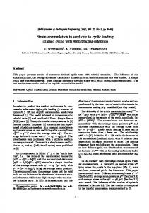
similar to their traditional counterparts (monolithic connections), while limiting the damage to the structural system and assuring full re-centring capability after the seismic event. A particularly efficient solution is provided by the “hybrid” system (Fig. 1a) where an appropriate combination of self-centring capacity (unbonded tendons plus axial load) and energy dissipation (mild steel dissipation devices) leads to a sort of “controlled rocking motion”, characterized by a peculiar “flag-shaped” hysteresis loop (Fig. 1b). This paper investigates the use of these innovative solutions for multi-storey timber buildings with seismic moment-resisting frames and jointed ductile connections. If the self-centring ductile system is to be adopted for timber buildings, Laminated Veneer Lumber (LVL) has important advantages compared to glue laminated and sawn timber, especially the randomization of wood defects and quality control during manufacture which lead to a nearly homogenous material with low variability of mechanical properties. This paper presents preliminary experimental results for hybrid exterior beam-tocolumn and column-to-foundation subassemblies under cyclic quasi-static unidirectional loading. Two
pure unbonded post-tensioned solutions and two hybrid solutions with internal epoxied dissipaters (i.e. mild steel reinforcement) are described for the exterior beam-to-column subassemblies, while three unbonded post-tensioned solutions with different levels of initial post-tensioning and two hybrid solutions with external dissipaters are investigated for the column-to-foundation specimen. The results are critically discussed by highlighting the enhanced performance of the hybrid connections. Rocking motion of Hybrid systems
a)
Self-centering
Energy Dissipation M
M
θ
Hybrid system
3 EXPERIMENTAL TESTS ON BEAM-TOCOLUMN SUBASSEMBLIES
M
θ
the aim of developing adequate connections between floors and the adjacent lateral load resisting systems, able to account for and minimize issues related to displacement incompatibility. In order to emphasise the higher seismic performance of the hybrid solutions, the response of typical “damageable” solutions (Buchanan & Fairweather 1993) will be investigated by means of numerical analyses and experimental tests, and finally compared with the proposed hybrid systems. The large scale testing of a multi-storey building comprising of frames, walls and floors will represent the ultimate validation of the proposed solutions. Design provisions and guidelines for the next generation of codes, as well as simplified analytical/modelling procedures will be also be developed and provided as final output of the research programme for the benefit of practitioner engineers and, more generally, end-users,
θ
3.1 Test set-up and loading regime b)
Mild steel or Unbonded posttensioned tendons dissipative devices
Figure 1. a) Hybrid systems developed under the PRESSS programme (courtesy of S. Nakaki); b) Flag-shape hysteresis rule.
2 OVERVIEW OF THE RESEARCH PROJECT An extensive research programme has been initiated in order to investigate the seismic performance of hybrid LVL connections for multi-storey timber buildings, as an extension of the concepts from precast concrete hybrid systems. The programme, divided into three initial phases, will involve the experimental and numerical investigations of the response of subassemblies, with special focus on the connection details, as well as of the whole lateral force resisting system, with and without floor systems. In the first phase of the research program, started under a joint agreement between the University of Canterbury and Carter Holt Harvey, particular emphasis was given to the conceptual development of shear wall specimens, beam-to-column subassemblies and column-to-foundation connections. In the second phase of the research, particular attention will be given to the global seismic performance of hybrid LVL systems, i.e. coupled wall systems, multi-storey seismic-resisting frames (with straight or draped profiles of the unbonded tendons, either internal or external), and dual (frame-wall) systems. In the third phase, alternative floor solutions based on timber, concrete-timber composite or precast concrete solutions will be investigated with
The adopted test set-up for quasi-static cyclic tests on beam-column joint subassemblies is shown in Figure 2. The beam is 1.5m long while the column is 2.0m high. The load was applied at the top of the test column, simulating the point of contraflexure in the real structure. 200
load cell (constant force)
load cell (cyclic force)
load cell (PT force)
Internal epoxied mild steel bars 300
2000
Unbonded PT tendon
1500 COLUMN SECTION
(BEAM CONTACT SECTION) Hybrid specimen 2
Hybrid specimen 1 105 45 105 200
50 200 50
50 150 150
105 45 105 As= 2 φ8 (top and bottom) Ap= 1 strand (7 wires, 0.99 cm2)
200 50
150 150
105 45 105 As= 1 φ10 (top and bottom) Ap= 1 strand (7 wires, 0.99 cm2)
Figure 2. Test set-up and geometry for the beam-column joint subassemblies
The loading protocol is characterized by a series of three cycles of increasing inter-storey drift ap-
formed bar located at the top and bottom of the beam. Both the dissipaters are epoxied into the LVL specimen in order to guarantee proper bond. 3.2 Unbonded post-tensioned-only solutions Two unbonded-post-tensioned-only specimens (i.e. lower bound of a hybrid system with fully recentring behaviour without specific energy dissipation devices) were tested with 0.4 fpy and 0.6 fpy levels of initial post-tensioning under the aforementioned loading protocol. Figure 4a illustrates the recorded values of lateral force vs. inter-storey drift (ratio of top-displacement and column height), characterised by a non-linear elastic hysteresis with fully re-centring properties. 8 6 Top-lateral Force [kN]
plied through the horizontal hydraulic actuator, following the acceptance criteria on innovative jointed precast concrete frame systems proposed by the ACI T1.1-01, ACI T1.1R-01 document (2001). The column axial load was kept constant during the experiments (120 kN). Figure 2 shows the geometry of the exterior beam-to-column subassembly. These specimens were tested with two different initial values of force in the unbonded post-tensioning tendons (0.4fpy and 0.6fpy, where fpy is the yield stress of the post-tensioning steel) and two hybrid solutions with internal energy dissipaters. Details of the beam sections at the column face are shown in the lower section of Figure 2, while the material properties, based on specific material testing, are reported in Table 1. The markedly different behaviour of the LVL material in the directions parallel and perpendicular to the grain can be easily recognised from the table. A significant reduction in strength (up to three times) has to be expected when loading perpendicular to the grain. This becomes a limiting consideration for the face of the column member where it is in contact with the end of the beam.
Unbonded PT Specimen (BEAM CONTACT SECTION)
4 2 0 -2
fp0 = 0.4fpy
-4
fp0 = 0.6fpy
-6 -8 0.03
a)
0.02
0.01
Unbonded PT Force [kN]
0
-0.01
-0.02
-0.03
Drift
120
fp0 = 0.6fpy 100
80
fp0 = 0.4fpy
60
40 -0.03
Figure 3. Internal dissipaters and construction details Table 1. Material properties for beam-to-column tests Materials (LVL, parallel to the grain): fc, Ec (LVL, perpend. to the grain): fp, Ep Mild steel bars, i.e. internal dissipaters: fsy 7-wire pre-stressing strand (Apt=99mm2): fpy
HY1, HY2 specimens 34 MPa, 13.2 GPa 12.0 MPa, 13.2 GPa 340 MPa (yield) 1530 MPa (yield) 1870 MPa (0.2% proof stress)
Figure 3a shows the details of the internal energy dissipaters for the hybrid specimen 1 and the corresponding stress-strain experimental curve. Figures 3b and 3c show respectively the beam contact surfaces, of the hybrid specimens 1 (HY1) and 2 (HY2) with positioning of the dissipaters. The first specimen uses two φ10 mm (grade 340) deformed bars, machined to a reduced diameter (φ8 mm) to create a fuse along an unbonded length of 50 mm, located at the top and bottom fibres, while the second specimen has one fully bonded φ10 mm (grade 340) de-
-0.02
-0.01
0
0.01
0.02
0.03
b) Drift Figure 4. Unbonded post-tensioned solution: a) lateral forcedrift curve; b) force vs. drift curve for the unbonded prestressing tendon
A minor amount of hysteretic dissipation is provided by the local non-linear behaviour of the LVL material at the column contact section, loaded in compression perpendicular to the grain. The observed loss of linearity or “knee-point”, i.e. similar to the yielding point of a dissipative traditional connection, is in this case due to geometrical (instead of material) non-linearity, i.e. a reduction of section stiffness due to a sudden relocation of the neutral axis position. As shown for precast concrete connections this loss of linearity indicatively occur at a level of bending moment equal to 2-3 times the decompression moment with a neutral axis position located around the centroid of the session. The reduced stiffness after the equivalent “yielding” corresponds to an increase in moment capacity primarily due to the elongation of the tendons as confirmed in Figure 4b. As anticipated, and shown in Figure 6, no visible damage could be detected in the
structural elements when lateral deformations were increased up to 2.75% inter-storey drift. The test was interrupted only to preserve the column specimen from possible damage due to compression crushing perpendicular to the grain before modifying it for the two hybrid solutions. 3.3 Hybrid solutions The same specimen which had been tested up to 2.75% drift in the pure unbonded post-tensioned case was then tested in the hybrid configuration HY1 and HY2, adopting the two solutions for internal dissipation devices previously described. A comprehensive design of the dissipaters was carried out in order to guarantee the desired ratio between the self-centring moment contribution and the energy-dissipating moment contribution, also referred to as λ-parameter (Palermo et al. 2005, NZS 3101:2006), assuming an initial post-tensioning level of 0.8 fpy. As a result, a stable flag-shape hysteresis behaviour was obtained, as expected, with recentring capacity (negligible static residual displacements) and adequate energy dissipation capacity, as shown in Figures 5a and 5b.
tion between the deformed mild steel bars and LVL through the epoxy. This reduction of stiffness is negligible and less emphasized when considering the hybrid specimen 2 with no unbonded length. The level of tendon force due to the initial prestressing plus elongation induced by the opening of the gap can be controlled with a proper design in order to guarantee an elastic contribution (full re-centring) without losses of prestress or undesired premature rupture of dissipators, up to the target level of drift. In this case an increase of 15% of the initial prestressing force was observed at 4.5% of drift. Besides the good hysteretic behaviour of the two specimens, Figure 6 shows that no visible damage occurred in the beam or the column at the third cycle to 4.5% drift in the positive direction. For the hybrid specimen 1 the final failure corresponded with the failure of one dissipater under repeated cycles after buckling in the unbonded length, while for the hybrid specimen 2 no failure occurred in the dissipaters but the test was interrupted at 4.5% drift to prevent possible yielding of the tendon.
Top-lateral Force [kN]
20 Hybrid Specimen 1 (BEAM CONTACT SECTION)
15 10 5 0 -5 -10 -15
fp0 = 0.8fpy
-20
a)
-0.05
-0.04
-0.03
-0.02
-0.01
0
0.01
0.02
0.03
0.04
0.05
Drift
Top-lateral Force [kN]
15 10
Hybrid Specimen 2 (BEAM CONTACT SECTION)
5
Figure 6. Hybrid solution: appearance of the specimen at 4.5% drift
0 -5 -10 fp0 = 0.8fpy
-15
b)
-0,05
-0,04
-0,03
-0,02
-0,01
0
0,01
0,02
0,03
0,04
0,05
4 EXPERIMENTAL TESTS ON COLUMN-TOFOUNDATION CONNECTIONS
Drift
Figure 5. a) lateral force-drift curve of hybrid specimen 1; b) lateral force-drift curve of hybrid specimen 2.
In particular, the HY2 specimen, one deformed bar at the top and bottom of the cross-section, highlights a higher self-centring capacity and a reduced hysteresis loop due to the smaller amount of dissipation capacity provided by the dissipaters. In both the hybrid solutions shown in Figure 5, the equivalent yielding point corresponds to the actual yielding of the dissipation devices, observed at 0.8% interstorey drift. During repeated cycles at a mediumhigh level of drift, some onset of stiffness degradation was observed, probably due to bond deteriora-
4.1 Test set-up and loading regime As part of the investigation of frame subassemblies, a series of quasi-static cyclic tests on cantilever columns connected to the foundation have been carried out. As shown in Figure 7, the specimen consisted of a square LVL hollow column (1.6 m high) connected to a steel foundation. It is worth noting that the same solution can be directly implemented to concrete foundations. The cantilever column was loaded at the expected point of contra-flexure within a frame systems, thus mid-height of the inter-storey height. The loading protocol was the same as that
adopted for the above mentioned beam-to-column subassemblies. There was no additional axial load applied, and the initial post-tensioning of the two tendons passing through the foundation (Fig. 7) includes the axial force due to the gravity load. TEST SET-UP 150 kN Load Cells
Unbounded post-tensioned cables
Reaction Frame Actuators
50kN Load Cell
1,600
Transducer
Dissipaters 265
COLUMN SECTION
Steel Foundation
450
90
360
450
450
DISSIP ATERS DETAIL
els of initial post-tensioning under the same loading protocol. Figure 8a illustrates the recorded values of lateral force vs. drift. The behaviour is very similar to the unbonded post tensioned beam-to-column solutions presented in paragraph 3.2. The level of “yielding moment” depends on the initial posttensioning level. However, in this case there is negligible hysteretic dissipation due to the non-linear behaviour of the material, when compared to the beam-to-column subassembly, since the rocking surface is LVL parallel to the grain in contact with steel. Moreover, the “knee-point” due to geometrical non-linearity is more clearly delineated due to a more sudden relocation of the neutral axis position with end grain of LVL in contact with steel. Similar considerations apply to the plot of tendon forces vs. drift (Fig. 8b). The tests were stopped at 4.5% drift, in order to preserve the bottom of the LVL column test specimen from possible crushing damage, and to prevent yielding of the two tendons.
Figure 7. Test set-up and geometry for column-to-foundation test specimens
Top-lateral Force [kN]
35
HY1, HY2 specimens 28 MPa, 9.0 GPa
a)
The top end of each external dissipater is connected to an external steel case fixed to the LVL column, and the bottom end is fixed to the steel foundation. The column specimen illustrated in Figure 7 has been used for five tests: three unbonded posttensioned solutions with different initial values of post-tensioning (0.3fpy, 0.4fpy, 0.5fpy) and two hybrid solutions with external energy dissipaters. Details of the material properties, based on specific material testing, are shown in Table 2. Figure 7 (lower part) shows details of the energy dissipaters, consisting of steel rods designed to yield in both tension and in compression. The rods are encased in steel tubes injected with epoxy to prevent buckling during the tests. Similar dissipaters have been implemented and tested by Pampanin et al. (2006) for hybrid solutions in precast concrete beam-column joint. 4.2 Unbonded post-tensioned solutions Three unbonded post-tensioned specimens with no energy dissipaters were tested with the three lev-
-5 fp0 = 0.3fpy
-15
fp0 = 0.4fpy fp0 = 0.5fpy
-0,05 140
Unbonded PT Force [kN]
1530 MPa (yield) 1870 MPa (0.2% proof stress)
5
-35
10.0 MPa, 9.0 GPa 340 MPa (yield)
15
-25
Table 2. Material properties for column-to-foundation tests Materials (LVL Hy90, parallel to the grain): fc, Ec (LVL Hy90, perpend. to the grain): fp, Ep External dissipaters with steel case: fsy 7-wire pre-stressing strand (Apt=99mm2): fpy
Unbonded PT specimens
25
-0,03
Drift
0,01
0,03
0,05
Unbonded PT specimens
120
fp0 = 0.5fpy
fp0 = 0.4fpy
100 80 60 Tendon East
40
-0,05
Tendon West
fp0 = 0.3fpy
20
b)
-0,01
-0,03
-0,01 Drift
0,01
0,03
0,05
Figure 8. Unbonded post-tensioned solution: a) lateral forcedrift curves; b) force vs. drift curves for the unbonded prestressing tendon
4.3 Hybrid solution Two hybrid solutions were investigated using the same specimen which had been previously tested for the three post-tensioned-only solutions, thus without dissipaters. The two hybrid specimens differ only in the size of the dissipaters, since the location of the dissipaters and the unbonded post-tensioned tendons, and their initial post-tensioning level (0.5 fpy) is the same. Each hybrid specimen had two external dissipaters placed on each side, with an effective length of 130 mm. For the first specimen, φ10 mm (grade 340) deformed bars, machined down to a reduced diameter (φ9 mm) have been adopted, while
the second specimen used φ10 mm deformed bars, machined down to a reduced diameter of φ8 mm. Top-lateral Force [kN]
60 40
Hybrid specimen 1 (external fused dissipaters φ9 mm)
20 0 -20 -40
fp0 = 0.5fpy
-60
a)
-0,05
Top-lateral Force [kN]
60 40
-0,03
-0,01
Drift
0,01
0,03
0,05
Hybrid specimen 2 (external fused dissipaters φ8 mm)
20 0 -20 -40
fp0 = 0.5fpy
-60
b)
-0,05
-0,03
-0,01
Drift
0,01
0,03
0,05
Figure 9. a) lateral force-drift curve of hybrid specimen 1; b) lateral force-drift curve of hybrid specimen 2.
5 CONCLUSIONS The preliminary experimental results of cyclic quasi-static tests on hybrid LVL beam-to-column and column-to-foundation subassemblies confirmed the enhanced performance of these dry jointed ductile connections. In all cases there were high levels of ductility, and the residual deformations after simulated seismic loading were found to be negligible. The hybrid systems showed a significantly greater level of energy dissipation. The lack of damage in the structural elements, with the dissipaters being the only sacrificial parts of the connection system, can guarantee improved seismic performance and improved reparability compared to traditional solutions in timber construction (e.g. nailed or steel dowel connections). These factors inevitably lead to a significant reduction of expected repair costs (including downtime) after a significant seismic event. The hybrid solutions with external dissipaters may be preferred to those with internal epoxied bars due to the much easier replacement after a seismic event, even if the construction technology for external dissipaters is more expensive. Similar considerations encourage the adoption of steel-LVL contact surfaces instead of LVL-LVL contact surfaces. Based on these favourable results, further experimental and analytical investigations for the development of LVL hybrid solutions are currently ongoing and will be extended to cover alternative lateral load resisting systems. 6 REFERENCES
Figure 10. Hybrid solution: appearance of the specimen at 4.5% drift
Both the specimens were designed in order to guarantee a proper value of the moment ratio λ. In particular, as shown in Figures 9a and 9b, the higher design value of λ of the second specimen led to a higher self-centring capacity but a reduced dissipation capacity. Both specimens show very stable flagshaped hysteresis behaviour. Moreover, for the hybrid column-to-foundation specimens, there is less stiffness degradation than for the hybrid beam-tocolumn solutions described in paragraph 3.3. This is mainly due to the absence of bond degradation of the dissipaters (one end being fixed to the steel foundation), and to the larger rigidity of the contact surface (LVL end grain being in contact with a steel surface rather than in contact with LVL loaded perpendicular to the grain where compressive crushing can occur. Finally, Figure 10 shows no visible damage in the column after the third cycle of 4.5% drift in the positive direction.
ACI T1.1-01 & ACI T1.1R-01 2001. Acceptance Criteria for Moment Frames Based on Structural Testing (T1.1-01) and Commentary (T1.1R-01), ACI Innovation Task Group 1 and Collaborators. Buchanan, A.H. & Fairweather R.H. 1993. Seismic Design of Glulam Structures, Bulletin of the New Zealand National Society for Earthquake Engineering, Vol 26(4) 415-436. Christopoulos, C., Filiatrault, A., Uang, C.M. & Folz, B. 2002. Post-tensioned Energy Dissipating Connections for Moment Resisting Steel Frames, ASCE Journal of Structural Engineering, Vol. 128(9) 1111-1120. NZS 3101:2006. Standards New Zealand, Design of Concrete Structures, Appendix B: Special Provisions for the Seismic Design of Ductile Jointed Precast Concrete Structural Systems. Palermo A., Pampanin S., Calvi G. M. (2005). “Concept and Development of Hybrid Solutions for Seismic Resistant Bridge Systems.” Journal of Earthquake Engineering, 9(5): 1-23. Pampanin S., Palermo A., Amaris A. (2006), “Implementation and Testing of Advanced Solutions for Jointed Ductile Seismic Resisting Frames.” Proceedings 2nd fib Congress, June 5-8, Naples, Italy. Priestley, M.J.N., Sritharan, S., Conley, J. R. & Pampanin, S. 1999. Preliminary Results and Conclusions from the PRESSS Five-story Precast Concrete Test-building, PCI Journal, Vol 44(6) 42-67.