This method is shown to be inadequate for mutu- ally coupled magnet systems. As a solution to this problem a theory of voltage detection for mutually coupled ...
109
IEEE TRANSACTIONS ON APPLIED SUPERCONDUCTIVITY, VOL. 4, NO. 3, SEPTEMBER 1994
Quench Detection of Multiple Magnet System Mohamed A. Hilal, George VCscey, John M. Pfotenhauer, and Felix Kessler Abstract-Magnet protection mandates the detection of any normal zone so that the magnet can be safely discharged. This is usually achieved by having a center voltage tap and two voltage taps at both ends of the windings. The voltage across the two sections of the winding is compared and balanced for inductance. Any voltage signal is then due only to the presence of a normal zone. This method is shown to be inadequate for mutually coupled magnet systems. As a solution to this problem a theory of voltage detection for mutually coupled magnets is presented along with a voltage detection circuit based on Gaussian elimination. The method is confirmed by experiment. Two equivalent solutions are presented which involve either additional voltage taps or the incorporation of dZ/dt signals from the coupled magnets.
INTRODUCTION
S
UPERCONDUCTING magnet protection schemes may be broadly categorized into two classes-passive and active. Magnets which are operated in a persistent mode are likely to have passive protection systems such as subdivided sections with associated cold dump resistors or diodes (see, for example, Wilson [l]).On the other hand, magnets which are continually connected to current sources and/or which have large associated stored energies typically require an active protection scheme. The vital components of an active system include a quench detection system, current commutating switches, and a dump resistor. In such systems magnet protection is usually achieved by the fast detection of an existing normal zone so that the magnet can be discharged. It is necessary that the detection circuit responds to small normal zone resistive voltages, but it should not respond to other voltage spikes or fluctuations which may be induced by other sources such as power supplies. A widely used technique for magnet protection is to have three voltage taps with one of the voltage taps located at the center of the windings. The voltages across the two halves of the magnet are compared and balanced so that they are equal; a normal zone will induce an imbalance voltage and can thus be detected. The above technique has been successfully used for a single magnet system. The same technique is also widely used for multiple magnet systems by installing three voltage taps in each magnet. The Manuscript received January 3, 1994. M. A. Hilal, J. Pfotenhauer, and F. Kessler are with the Applied Superconductivity Center, University of Wisconsin-Madison, Madison, WI 53706. G. Vkscey is with the Paul Scherer Institute, Villigen, Switzerland. IEEE Log Number 9402751.
voltage across the magnet section is balanced. It is then assumed that any imbalance voltage is primarily due to the presence of normal zones. It is shown in this study that this is not valid unless constraints are imposed on the charging current of the different magnets. A new quench detection technique for a multiple magnet system is then discussed. This system is of particular importance to coupled magnet systems such as fusion torroids, hybrid magnets, and modular SMES systems. In the new technique, imbalance voltages will only exist as a result of the presence of a normal zone. The new detection circuit does not respond to the power supply voltage spikes or any other inductive voltage spikes. It does not require any constraints on the magnets charging. VOLTAGE DETECTIONTHEORY A. Conventional Voltage Detection Method To illustrate the problem, we first consider the single magnet detection circuit, Fig. 1. V, and V, are measured across the voltage taps shown in Fig. 1. V, and V, are given by
v, = a , i + V,
(1)
V, = a, I .
(2)
and
The circuit is thus described by two equations where V, and V, are known from measurements. Equations (1) and (2) have two unknowns 1 and VR. The normal zone voltage V, is given by (3) The above equations have a unique solution, and a voltage signal is always detected in the presence of a normal zone (3). Note that in the absence of any normal zone, V,/V, = a,/a, independent of the charging rate. Variation of the current charging rate, such as current supply ripples, does not lead to any normal zone false detection. The measurement technique used for normal zone detection is equivalent to the above mathematical description. The voltage signal V, is adjusted using an amplifier so that the difference V, - GV,, where G is the amplifier gain, is zero. Note that G should equal to a l / a z . The measured imbalance voltage is given by (3) and should be equal to the normal zone voltage.
1051-8223/94$04.00 0 1994 IEEE
110
IEEE TRANSACTIONS ON APPLIED SUPERCONDUCTIVITY,VOL. 4, NO. 3, SEPTEMBER 1994
‘1
‘ 2
9
r+-
a112
; lv vi2
Fig. 1. Single winding voltage taps arrangement.
We consider next the two-magnet system shown in Fig. 2 where the two windings are mutually coupled. We assume that each magnet has two pairs of voltage taps, as shown in Fig. 2. The voltages across the two pairs of one of the windings, e.g., the first winding, are given by
a121
I
i
I I
Fig. 2. Voltage taps arrangement for two windings using conventional technique.
magnet k
section 1
and magnet j
Section 2
where V,, is the voltage across the first half of the first magnet, V,, is the voltage across the second half of the first magnet, all,, alZ1is the self-inductance of the first magnet, all,, alZz is the mutual inductance (between the two magnets), I , = dIl/dt, and I, = dl,/dt of the first and the second magnet, respectively, and V, is the normal zone voltage. Note that there are three unknowns (I,, I,, and V,) and two algebraic equations. The above equations do not have a unique solution without imposing a constraint such as having a given ratio of the current charging rates. The normal zone voltage in this case is given by
v
--V
-
a11 + a12a1 a2, + a2,a, V,
where a, is the current charging rate ratio i2/Il in the two windings. As can be seen, the normal zone voltage depends on a,; and, since a , will vary, inductive voltage spikes will produce false voltage signals initiating an energy dump in the absence of a real quench. The above technique cannot thus be used for a multiple magnet system.
section
I
section m
V,,
$1 I 3
Fig. 3. Voltage taps arrangement for the kth magnet.
across the ith section of the kth magnet, Fig. 3, are given bY
where Vki is the voltage across the ith section of the kth magnet, aki, is the mutual inductance between the ith section of the kth magnet and the jth magnet, and VR,kl B. VoltageDetection Technique for a Multiple Magnet System is the voltage across the normal zone of the ith section of As illustrated above, the conventional detection circuits the kth magnet. of having three voltage taps and comparing the voltage Note that there are ( n 1) unknowns, Il to I, and across the two magnet halves cannot be used for a multi- VR,ki, and m equations given that there is one normal ple magnet system. The measured imbalance voltage dur- zone only. A unique solution thus mandates dividing each ing magnet system operation may not be necessarily due magnet into m = ( n 1) sections and requires having to the presence of a normal resistive zone and may lead to ( n + 1) pairs of voltage taps. The Gaussian elimination a premature magnet discharge. technique to solve the above algebraic equations is disLet there be n magnets which are inductively coupled. cussed here since it corresponds to an experimental proEach magnet has m pairs of voltage taps. The voltages cedure which can be implemented in the design and the
+
+
111
HILAL et al.: QUENCH DETECTION OF MULTIPLE MAGNET SYSTEM
construction of voltage detection circuits for multiple magnet systems. First we eliminate I,, from all equations of the kth magnet. Using the (n + 11th equation, we employ the standard procedure of multiplying the ith equation, where i goes from 1 to n, by the ratio ak,n I,n/ak,i,n and then subtracting the (n 11th equation from each of the others. The procedure is repeated using the nth equation to eliminate I,,-, from the remaining (n - 1) equations. This is repeated until all the n unknowns are eliminated from the first equation. The first equation can be solved for the first unknown which is assumed to be the resistive voltage. We assumed that the kth magnet has one normal zone only. If the magnet has several normal zones, the measured total normal voltage will be a combination of the normal voltage across each zone. There is a possibility that the combined voltage is zero, but such possibility is remote. This is similar to having one magnet where equal resistance normal zones exist one in each section. The proposed voltage detection circuit is shown in Fig. 4 and the experimental procedure based on the above method, with respect to the kth magnet is as follows. 1) Initiate charging the kth magnet. 2) As the magnet is being charged balance the voltage across all sections of the kth magnet using the first amplifier set so that the voltages at each summing point S, is zero. From this time on the voltages are insensitive to any current changes in the kth magnet. 3) Initiate charging the jth magnet. Repeat the above procedure to eliminate the voltages across all sections of the kth magnet using the second set of amplifiers. The voltages are now insensitive to current changes in the jth magnet. 4) Repeat steps 1 and 2 for each remaining magnet, using the next set of amplifiers. 5) Repeat the entire procedure, 1, 2, 3, and 4 for each magnet which is being monitored for normal zone voltages. As seen in Fig. 4,the voltage across the last two taps is zero as long as no normal zone exists and is equal to the voltage across the normal zone if a magnet quench is taking place. The above procedure cannot be used for existing magnet systems when each magnet has three voltage taps only and when it is not practical to unwind the magnet to install more voltage taps. To implement the above theory for use with the existing systems, the current charging rate of each magnet must be measured. This can be achieved by winding a toroidal coil, or Rowgowski coil, around a current lead on each magnet where the voltage output of the toroidial coil is proportional to I. T o ensure that the coil voltage signal is primarily due to I , the coil should be positioned far enough from the magnet system and should be oriented so that it has minimum coupling to the magnet system. The procedure for voltage detection in this case is as follows. 1) Charge the nth magnet and eliminate the voltage +
+
across both magnet sections of the kth magnet by adjusting the gains at amplifier set n so that the voltages after the summing points S, are equal to zero; see Fig. 5. 2) Charge the (n - 1)th magnet and repeat step 1 to eliminate the voltage across the kth magnet sections after summing points S, 3) Repeat step 1 for magnet k by charging the rest of the magnets one at a time. 4) Charge the kth magnet and adjust amplifier k to compensate for the difference in the inductance of the two halves of magnet k. 5 ) Repeat steps 1 to 4 for all magnets.
,.
EXPERIMENTAL VERIFICATION
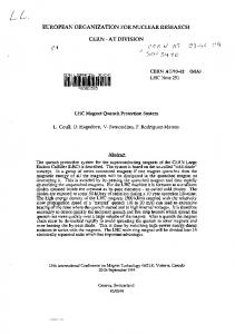
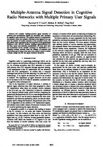
A. Experiment Description We have conducted experiments to confirm the above voltage detection theory. The experimental arrangement details and results are reported elsewhere [l], [2]. Two superconducting solenoid coils were used, Fig. 6, and the dimensions of the coils are given in Table I. The inner coil is segmented to three sections which are not equal in length in order to have large unbalanced voltages. The inner coil is instrumented with four voltage taps. No voltage taps are used within the outer coil. The voltage detection circuit is shown in Fig. 7. B. Experimental Results The two coils are simultaneously charged at different but fixed rates. The conventional voltage detection technique is first implemented, Fig. 6(a). The voltages V, and V, are balanced only with one specific value of I,/I,; otherwise a nonzero voltage signal is observed, Figs. 8(a) and 8(b). The presence of a voltage signal without having a normal zone confirms that the conventional voltage technique is inadequate for a multiple magnet system. The experiment is then performed using all voltage taps and the new voltage detection circuit, Fig. 7(b). The voltages are balanced as discussed before. The two coils are then charged. The charging rate of each coil is independently varied, Fig. 9(a); and the voltage signal obtained is very small, Fig. 9. A section of the inner and the voltage signal obtained is very small, Fig. 9. A section of the inner solenoid is driven normal using a heater and a voltage signal is observed, Fig. 9(b). The heater power versus time is shown in Fig. 9(c). Finally, the quench detection circuit, shown in Fig. 7(c), is used with the voltage V, being replaced by a signal proportional to dI,/dt. A Rogowski pick-up coil located at room temperature is used to provide the dI,/dt signal. G, and G, perform the function of compensating for the voltages induced to sections 1 and 2, respectively, of coil 1 due to dIJdt. G, compensates for the difference in the self-inductances of sections 1 and 2 of coil 1, thereby eliminating sensitivity to dI,/dt. As shown in Fig. 10 the output voltage is insensitive to dI,/dt and dI,/dt, but displays the resistive voltage which corresponds to that generated
IEEE TRANSACTIONS ON APPLIED SUPERCONDUCTIVITY, VOL. 4, NO. 3, SEPTEMBER 1994
112
magnet
sectlon 1
...........
sactlon 2
...........
sectlon 3
...........
.... .... .... .... ....
.. ... .. .. .... .. .. .. .. ..
... ... . . .. . . ..
,
,
. . . . . .
.
.
.
.
.
.. .. . . . . . . . .. .. .. .. .. . .. .. .. . . . . . . . ..
.
section m-2
sectlon m-1
section m
3
1st amplifier-set Fig. 4. Voltage detection circuit for multiple windings.
magnet k
Ik -+-I 'k
8eclon 1
section 2
. . . . ... . . .. .. .
magnet 2
I
........
Yj c: CL:
aj
I I
. . . .. ... . . .. .. .
... .. . ... ... ... .. :, .
.. . ... . .. .. . ... .. :, .
.. . ... . .. . .. . .. :. .
.. . ... . .. . .. . .. :, .
k
amplifiers 1
amplifiers - ' 2
.............
....
X:
mi
.............
mj *
m: c:
pi Ej
.. . . .. ,:G'.. ,:a., .............. . .
. . .!. .
............. ..........
ampliliers n-1
amplifiers n
pickup coils Fig. 5. Voltage detection circuit using pick up coils for Z measurement.
113
HILAL et al.: QUENCH DETECTION OF MULTIPLE MAGNET SYSTEM
TABLE I COILDIMENSIONS
I. D. (cm) magnet 1 top section middle section bottom section
1.91 1.91 1.91
magnet 2
7.62
6.99 6.99 6.99
4.76 3.81 3.49
15.2
0.34 0.29 0.20
24.1
19.8
magnet 1
(a)
v2
0.D. (cm) height (cm) inductance (H)
Jj I .
I
I
100
150
I
magnet 2
0
50
200
time[s] r--
I
Fig. 8. Detection circuit output. (a) Currents in the magnets. (b) Voltage using two pairs of taps.
Fig. 6. Magnets arrangement. (a) Using two sections only for voltage detection. (b) Using all three sections for voltage detection.
; ; + - - - $F - l v v2 v3
vi "2
dlp/dt
-ysI; -
0 2
f
12:
I
.
I
-
G2
Fig. 7. Voltage detection circuit. (a) Using two pairs of taps. (b) Using three pairs of taps. (c) Using I.
by the heater. In this test we demonstrated the idea only -greater care in setting the precise values of GI and G, will eliminate all residue of the dl,/dt signal at the output, Note that this quench detection method is preferred for a magnet system where the number of coupled magnets may change. Traditional two-paired-voltage-tap detection systems can be augmented by signals proportional to dIi/dt for each ith magnet added to the system.
f
0
I
S'O
100 time [SI
140
200
Fig. 9. Magnet current and detection circuit output voltage using three pairs of voltage taps. (a) Magnets current. (b) Detection circuit output voltage-signal at R represents normal zone voltage generated by heater. (c) Heater power versus time.
CONCLUSIONS Conventional voltage detection techniques are not appropriate to use for multiple magnet systems since the initial voltage balancing does not ensure that the voltage detection circuit for n magnet systems require having n + 1 pairs of voltage taps or measuring I for each magnet.
IEEE TRANSACTIONS ON APPLIED SUPERCONDUCTIVITY, VOL. 4, NO. 3, SEPTEMBER 1994
114
12 L
I
I
General Dynamics, and the Swiss Institute for Nuclear Research. His interests focused on magnet system design and cryogenics. During 1991 and 1992 he developed the ideas for coupled magnet quench detection. Dr. Hilal passed away unexpectedly on November 5, 1992, during a brief hospitalization in Madison, WI.
George Vescey, photograph and biography unavailable at the time of
publication.
-
o
.............................................................................................
o l50 S
E
>-
f
......
..... ..........:. ........
I
50
I I
0
50
timeis]
100
...
..... -
,
150
Fig. 10. (a) Magnet current. (b) dZ2/dt. (c) Detection circuit output voltage employing Rogowski coil for voltage compensation.
REFERENCES [l] M. N. Wilson, SuperconductingMagnets. Oxford: Clarendon Press, 1983, ch. 9. [2] J. M. Pfotenhauer, F. Kessler, and M. A. Hilal, “Voltage detection and magnet protection,” submitted to ZEEE Trans. Magn., Aug. 1992. [3] J. M. Pfotenhauer, F. Bodker, Z. Jiang, 0. D. Lokken, B. Tao, D. Yu, G. E. McIntosh, and L. E. Nickels, “A 100 kA He I1 cooled test facility,” in R. W. Fast (Ed.), Advances in Cryogenic Engineering. New York Plenum. 1991. DO. 155-162.
Mohamed A. Hilal was born in Egypt in 1945. He received the B.S. degree from the University of Alexandria, Egypt, the Ph.D. degree in nuclear engineering from the University of Wisconsin-Madison in 1973. From 1976 to 1983 he held faculty positions at the University of Wisconsin-Madison, Michigan Technology University, and the University of Petroleum and Minerals in Saudi Arabia. Subsequently he was a Senior Scientist with the Applied Superconductivity Center at UW-Madison,
John M. Pfotenhauer was born in Kamloops, B.C., Canada, in 1957. He received the B.A. degree in physics and religion from St. Olaf College in 1979 and the M.A. and Ph.D. degrees in physics from the University of Oregon in 1981 and 1984, respectively. In 1984 he joined the Applied Superconductivity Center at the University of WisconsinMadison. During his advancement to the position of Senoir Scientist, he developed and carried out experiments for stability measurements of He I1 cooled superconductors including the full scale test of the 60 kA SMES conductor. In 1993 he also joined the faculty in the Departments of Mechanical Engineering and Nuclear Engineering-Engineering Physics at UW-Madison. His present interests include superconductor stability, quench detection, and high T, current leads.
Felix Kessler was born in Basle, Switzerland, in
1966. He received a diploma in electrical engineering from the Swiss Federal Institute of Technology, Zurich, in 1991. From 1991 to 1993 he worked at the Applied Superconductivity Center of the University of Wisconsin-Madison, where his background in electronics was utilized for the design and implementation of magnet protection systems using state-of-the-art microprocessor circuits. He is currently living in Basle, Switzerland.