1
Radio Sleep Mode Optimization in Wireless Sensor Networks Raja Jurdak∗† , Antonio G. Ruzzelli‡ , and G.M.P. O’Hare‡ ∗ CSIRO ICT Centre † University of Queensland ‡ University College Dublin {
[email protected],
[email protected],
[email protected]}
Abstract—Energy-efficiency is a central challenge in sensor networks, and the radio is a major contributor to overall energy node consumption. Current energy-efficient MAC protocols for sensor networks use a fixed low power radio mode for putting the radio to sleep. Fixed low power modes involve an inherent tradeoff: deep sleep modes have low current draw and high energy cost and latency for switching the radio to active mode, while light sleep modes have quick and inexpensive switching to active mode with a higher current draw. This paper proposes adaptive radio low power sleep modes based on current traffic conditions in the network. It first introduces a comprehensive node energy model, which includes energy components for radio switching, transmission, reception, listening, and sleeping, as well as the often disregarded micro-controller energy component for determining the optimal sleep mode and MAC protocol to use for given traffic scenarios. The model is then used for evaluating the energy-related performance of our recently proposed RFIDImpulse protocol enhanced with adaptive low power modes, and comparing it against BMAC and IEEE 802.15.4, for both MicaZ and TelosB platforms under varying data rates. The comparative analysis confirms that RFIDImpulse with adaptive low power modes provides up to 20 times lower energy consumption than IEEE 802.15.4 in low traffic scenario. The evaluation also yields the optimal settings of low power modes on the basis of data rates for each node platform, and it provides guidelines and a simple algorithm for the selection of appropriate MAC protocol, low power mode, and node platform for a given set of traffic requirements of a sensor network application. Index Terms—RFID, wake-up radio, sleep mode, adaptive, energy-efficiency, MAC protocols, routing protocols, energy model, sensor networks
I. I NTRODUCTION Energy-efficiency is a central challenge in sensor networks, as battery replacement is costly and often difficult in inaccessible deployment regions. While solar energy harvesting can secure enough energy supply for certain outdoor applications, its applicability is seasonal at best
in some regions of the world, and quite challenging in heavily shaded areas, such as forests and urban areas. Several efforts have addressed energy efficiency in sensor networks, through the design of energy saving MAC protocols, such as duty cycling protocols [6] or low power wake-up radio protocols [11], and routing protocols, such as [10]. Radio energy consumption is a major component contributing to the overall energy consumption at each node. Current MAC protocols put the radio in sleep mode while there is no data to send or receive, in order to minimize energy consumption. Although most radios for sensor networks support multiple sleep modes, the radio sleep mode in current MAC protocols is static. Choosing a static low power mode involves an energy and delay tradeoff. For example, the CC2420 [4] radio provides three different radio low power modes. The deepest sleep mode, which turns off the oscillator and voltage regulator, provides the lowest current draw of all low power modes. However, it also involves the highest energy cost and the longest latency for switching the radio back to active mode. In contrast, the lightest sleep mode provides a transition to active mode that is quick and energy inexpensive, but it has a higher current draw. In a low traffic scenario, it is better to use the deep sleep mode as nodes spend more time sleeping than switching back and forth between sleep mode and active mode. In a high traffic scenario, a lighter sleep mode is more suitable as the cost of switching the radio frequently into deep sleep mode would exceed the energy saving of the deep sleep mode’s low current draw. To address this tradeoff, this paper proposes adaptive radio power modes that dynamically change according to current traffic conditions in the network. To demonstrate the benefits of adaptive sleep modes, we incorporate them into our recently proposed RFIDImpulse mechanism [14], [1], which uses RFID tags as an out-ofband wake up radio for sensor networks [2], [13], and compare its performance against the popular BMAC [6]
2
protocol and the IEEE 802.15.4 standard [16] across two pervasive sensor node platforms, namely MicaZ [8] and TelosB [9]. The performance evaluation of proposed protocols generally considers the radio energy consumption, including receiving, transmitting, listening, and sleeping energy consumption components, but it disregards the switching energy component [15] that is appreciable for any protocol that switches nodes between active and sleep modes in low traffic conditions. While in some cases protocol evaluations consider the sensor energy consumption, they often ignore the energy consumption at the micro-controller unit (MCU). Disregarding MCU power consumption typically stems from two assumptions: (1) that sensor networks are homogeneous and use the same node platform, in which case the MCU power component does not affect relative power consumption among nodes or protocols; and (2) that MCU power consumption is negligible relative to radio power consumption. However, MCU power consumption becomes relevant for heterogeneous sensor networks that include multiple node platforms or for choosing suitable node platforms and protocols for a particular application scenario, especially because MCU’s do not use their lowest power state while the nodes are idle. In order to determine how to adapt low power modes in RFIDImpulse and to compare the MAC protocols fairly across different platforms, this paper presents a sensor node energy consumption model that includes switching energy, micro-controller energy components, in addition to energy consumption of the physical sensors. The model enhances existing models [6], is generalizable to any MAC protocol and node platform, and serves as the basis for evaluating the energy consumption of sleep mode configurations for given traffic loads and for determining the optimal protocol/sleep mode configuration. Because the integration of RFID tags with sensor nodes is not yet complete, our evaluation uses measured current draw of the CC2420 radio, which is used in both TelosB and MicaZ, in each of its operating modes, for comparing the protocols through a custombuilt Matlab simulation model [1]. The comparison of the protocols under different traffic loads yields guidelines for selecting appropriate MAC protocols and node platforms for specific traffic requirements of an application. We also determine the optimal radio low power mode within RFIDImpulse as the data rate varies. This paper extends the earlier work in [1] by providing an acknowledgement mechanism for RFIDImpulse to support reliability. It also consolidates the energy model on which it proposes a sleep mode and protocol selection algorithm by incorporating sensor energy consumption.
This paper also elaborates on the delay implications of varying radio sleep modes and provides delay results for an experimental scenario. It also expands the performance evaluation of the energy consumption relative to effective transmission rate, and a more comprehensive discussion of adaptive sleep modes. In sum, the novel contributions of this paper are fivefold: • Proposal of adaptive radio low power sleep modes within our previously proposed RFIDImpulse protocol that can dynamically change based on network or node traffic. • Introduction of an energy model that considers radio energy consumption, including transmission, reception, listening, sleeping, and switching energy components, micro-controller energy consumption, in addition to sensor energy consumption, as an enabler for comparing protocols across node platforms that use different processor boards. • Presentation of a simple algorithm based on the energy model for selecting the optimal protocol and sleep mode configuration for a given traffic load. • Energy-efficiency evaluation of BMAC, 802.15.4, and RFIDImpulse across 2 widely used node platforms, MicaZ and TelosB. The evaluation considers the dependence of energy-efficiency and optimal power mode on data rate. • Provision of guidelines based on the evaluation results for MAC protocol, power mode, and node platform selection according to the expected traffic requirements of the target application. The remainder of the paper is organized as follows. Section II presents the details of BMAC, IEEE 802.15.4 and the adaptive low power mode version of RFIDImpulse, while Section III provides the analytical model for evaluating the energy benefits of the three protocols, and it introduces the optimal sleep mode selection algorithm. Section V evaluates the performance of the three protocols for MicaZ and TelosB in a multi-hop network, while section VI discusses the results and concludes the paper. II. MAC P ROTOCOLS This section presents the three protocols under consideration separately: BMAC, IEEE 802.15.4 and RFIDImpulse. A. BMAC BMAC [6] is an asynchronous and lightweight sensor network MAC protocol that aims at providing versatile medium access while keeping the MAC functionality
3
as simple as possible. As an asynchronous protocol, BMAC eliminates the communication and processing overhead for scheduling and synchronization, which reduces energy consumption. BMAC enables each node to wake up periodically to check for channel activity. The wake-up period is referred to as the check interval. BMAC defines 8 check intervals, and each check interval corresponds to one of BMAC’s 8 listening modes. To ensure that all packets are heard by neighboring nodes, packets are sent with a preamble whose reception time is longer than the check interval. BMAC therefore defines 8 different preamble lengths referred to as transmit modes. Although several optimizations have improved over BMAC since its release, we consider it here as it still represents the building block of low power listening in the pervasive TinyOS-1.x operating system. B. IEEE 802.15.4 The 802.15.4 standard [16] provides MAC and PHY layer specifications for low data-rate and energy-efficient wireless networks. The MAC layer specifics include a beacon-enabled mode and a non-beacon enabled mode. The beacon-enabled mode represents an overkill and does not perform well in long-term monitoring application, so we focus here on the non-beacon enabled mode. In non-beacon enabled mode, no beacons are broadcast, so 802.15.4 reduces to plain CSMA/CA. Nodes use a binary exponential back-off mechanism to resolve collisions, with the variable BE defining the number of slots during each back-off period. The binary exponent of the backoff is initially set to 3, so any node with data to send selects a random time slot R1 during the first 2BE −1 = 7 time slots. The node then performs a clear channel assessment (CCA) during the timeslot R1 . If it detects no activity on the channel, then the node assumes the channel is free of carriers, so it reserves the channel for this time slot. Otherwise, if the channel is busy during time slot R1 , then the node backs off, increments BE by 1, and selects a random time slot R2 during the next 24 −1 = 15 time slots. The CCA process is repeated, and in case R2 is also busy, then the node repeats the process again for BE=5 to select R3 . If R3 is free, then the node sends its data during R3 . Otherwise, it drops the packet. C. RFIDImpulse 1) Overview: RFIDImpulse is a very low power radio wake-up scheme for sensor networks that relies on offthe-shelf RFID readers and tags. The basic functionality of RFIDImpulse is shown in Figure 1. All network nodes turn off their radios, including the voltage regulator and
the oscillator, as long as they have no packets to send or receive. The nodes also put their micro controller units (MCU) in power down mode during this idle period. A node that wishes to send a packet uses a built-in RFID reader to trigger an RFID tag that is located at the remote sensor node. The impulse from the sender causes the RFID tag at the intended receiver, which is connected to the external interrupt pin of the micro-controller at that node, to generate an interrupt to wake up the MCU. The MCU wakes up and activates the radio voltage regulator and oscillator in preparation for the incoming packets. After a short start up time of few milliseconds for the radio components, the radio at the receiver becomes fully active and sends a short acknowledgement message through the standard radio to the sender, indicating that the RFID wakeup was successful. Upon receiving the short acknowledgement from the receiver, the sender commences the transmission. Once the sender completes all its packet transmissions, both sender and receiver again turn off their radios and MCU’s, while the RFID tag remains in its low power idle mode for triggering future remote wake ups. If a sender fails to receive an acknowledgement from the receiver in response to an RFID wakeup signal, the sender assumes that the receiver tag did not detect the signal or that the signal level is too low to activate the receiver tag. The sender then transmits the RFID wakeup signal again, with a maximum of three retries. If the receiver acknowledges receipt of one of the RFID wakeup signals, then the sender proceeds with the transmission. Otherwise, the sender ceases its attempts to use RFID wakeup signals to this receiver. 2) Synergy with IEEE 802.15.4: Certain RFID standards operate in the ISM band, which is the same band as the IEEE 802.15.4. Consequently, an 802.15.4 radio can, in addition to serving as a general-purpose communication radio [12], potentially activate an active RFID tag through an energy harvesting strategy (such as with a suitable comparator [11]), which in turn drives the activation of the sensor node. Although RFIDImpulse is independent of the underlying MAC protocol, in the following discussion we describe how RFIDImpulse can enhance 802.15.4 MAC operation while maintaining compliancy with the standard. Section IV elaborates further on the implementation details for integrating RFID tags with IEEE 802.15.4. The non-beacon enabled mode in 802.15.4 demands that nodes wake up periodically for a contention access period in order to avoid keeping the nodes awake all of the time. With RFIDImpulse, a node can put its radio and MCU in sleep mode as long as it has no data to send and as long as its RFID tag has not been triggered.
4
Fig. 1.
High level timeline of RFIDImpulse
A node typically has data to transmit either when it has just sampled its sensors, or when it has received a packet that requires forwarding. In the latter case, the node is already awake and can attempt to forward the packet immediately. If the node has a packet to send due to a sensing event, the sensor output can generate an external interrupt at the MCU, in addition to the RFID tag, which enables sensing events to trigger a wake up event of an MCU in deep sleep. Once the MCU is awake, it activates the radio. The radio then performs CCA, as in 802.15.4, in a random byte slot within the first 7 slots. In case the selected slot is busy, then the sender backs off, goes into idle mode, and listens to the channel again in a random byte slot within the next 15 slots and so on. As a receiver, the node sleeps until its RFID tag is triggered. The node MCU is then activated through an external interrupt generated by the tag, and then the MCU turns on the radio. The node then listens to the channel exactly as in IEEE 802.15.4. If it does not receive any packets destined for it during the first 7 time units, it stays awake for an additional 15 time units. If there is still no packets, the radio stays on for another 31 time units, at which point the node either has started receiving the packet, or can go back into sleep mode. The maximum listening duration during an awake interval is therefore 54 time units that corresponds to about 17 ms. IEEE 802.15.4-compliant radios, such as CC2420, support three low power modes in addition to the active mode. The deepest sleep mode (M3) turns off the oscillator and voltage regulator, which minimizes radio energy consumption. Nodes that use M3 as a sleep mode must wait for about 2.4 ms every time they turn the radio back on, and the operation of switching the radio from mode M3 to active mode involve appreciable energy cost [15]. In contrast, the lightest sleep mode in the CC2420 (M1)
provides much quicker switching back to active mode (30µs) and much cheaper switching energy cost. However, the energy consumption of a node while its radio is in M1 sleeping state is 1 mA, compared to 0.2 mA for sleep mode M3. This exposes an energy and delay tradeoff between how deep a node sleeps and how often it wakes up to send or receive packets. Our model in this paper mainly focuses on energy components, while the delay implications of selecting different sleep modes in a multi-hop network are examined in Section III-I. 3) Tradeoffs: To address the energy tradeoff, RFIDImpulse supports traffic-based selection of low power radio modes. As a general rule, when the traffic load is high in a particular region of the network, nodes use lighter sleep modes as they have to wake up frequently to send and receive packets. It is not worthwhile for nodes to go into deeper sleep modes due to the higher latency and switching energy involved in frequent wake up transitions. When the traffic load is low in a particular region of the network, switching between sleep and active states is less frequent, so nodes use deeper sleep modes that provide the highest energy savings. Determining quantitative thresholds for optimal sleep mode selection demands an energy model that captures all components contributing to energy consumption at sensor nodes, which is the focus of the next section. III. A NALYTICAL M ODEL In order to model the energy consumption of the three MAC protocols, this section considers all the energy components that contribute to the overall energy consumption at a node, including the micro-controller unit, the sensors, and the radio. We consider a convergecast application where all nodes sample their sensor periodically and send the data towards the base station. The discussion here focuses on energy consumption during a single sampling period. A. Microcontroller Unit Energy The energy consumption at the micro-controller unit of sensor motes contributes significantly to energy consumption, yet this energy component is often disregarded when analyzing the energy consumption of sensor network communication protocols. While most protocols keep the MCU in standby mode when the node is idle, RFIDImpulse enables the MCU to go into power down mode and be awoken only through an external interrupt through the onboard RFID tag. As such, the MCU energy consumption while the node is idle: of f of f of f Emcu = Tmcu × Imcu ×V
(1)
5
of f is the total time during which the MCU is where Tmcu of f off, Imcu is the current draw of the MCU while the node of f is is idle, and V is the supply voltage. The value of Imcu pd equal to the power down current Imcu for RFIDImpulse. of f is equal to the standby current I sb Imcu mcu for other protocols. The MCU energy consumption during active mode is: on on on Emcu = Tmcu × Imcu ×V (2) on is the total time during which the MCU is where Tmcu on is the MCU current draw during normal on, and Imcu operation mode. The total MCU energy consumption, of f and E on . then, is simply the sum of Emcu mcu
B. Listening Energy We define the listening energy as the radio energy consumption when the radio is active but not receiving or sending any packets. Protocols that are based on low power listening, such as BMAC [6], have the following listening energy: S Ellpl = × TCH × Ilisten × V (3) CK where S is the sampling period, CK is the check interval, TCH is the time during which the node is awake every cycle, and Ilisten is the current draw of the radio in listening mode. In contrast, the listening energy in RFIDImpulse only depends on the number of packets to be sent or received, and not on the sampling period. A sender wakes up the intended receiver through the RFID tag, and then follows the IEEE 802.15.4 CCA and collision avoidance mechanism described in Section II-B. Considering the worst case in which the packet is sent, the sender performs CCA three times before finding a free slot. During all the other 51 time slots, the sender radio can go into idle mode, so the listening energy consumption per packet sent is: Esend = (3×TCCA ×Ilisten +51×TCCA ×Iα )×V (4)
where TCCA is the CCA duration, α is the radio sleep mode in use that is equal to M1 for idle mode, and Iα is the current draw of the radio while idle. Whenever the receiver tag in RFIDImpulse activates the MCU, and then the radio, the radio must stay on while the sender is attempting to transmit, which in the worst case is 54 time units. Thus, the listening energy per packet received in RFIDImpulse is: Erecv = 54 × TB × Ilisten × V
(5)
Finally, the total node listening energy for RFIDImpulse can be expressed as: Elrf id = Esend × Psent + Erecv × Precv
(6)
where Psent and Precv are the number of packets sent and received at the node. C. Switching Energy The switching energy component [15] is the energy consumed for switching the radio state between states, including normal, power down, and idle modes. The following equation determines the energy consumed for switching the radio from sleep mode α to active mode: (Iactive − Iα ) × Tα × V (7) 2 where Iactive is the current draw of the radio in active mode, Iα is the current draw of the radio in sleep mode α, and Tα is the time required for the radio to go from sleep mode α to active mode. Equation 7 assumes that the energy variation varies linearly while switching between sleep mode α and active mode. While the energy consumption due to switching can follow a non-linear pattern, the linear approximation is reasonable for differentiating between the high cost of switching from a deep sleep mode and the low cost of switching from a light sleep mode. The switching energy consumption of duty cycling protocols relates to the length of the sampling period and the check interval. For a fixed check interval, the number of times that a node switches its radio on and off is proportional to the length of the channel sampling period. More specifically: α Eswitch =
S α × 2 × Eswitch (8) CK The factor of 2 in the above equation accounts for switching back to mode α from active mode. In RFIDImpulse, the switching energy does not depend on the sampling period, but it depends on the number of packets sent and received. As a receiver, a node switches from sleep mode to active mode whenever its tag is activated, and it stays awake for a maximum of 54 time units during the contention period. As a sender, a node switches from sleep to active mode to perform CCA. If the channel is busy, then the node goes into idle mode until the next back-off interval. This process may be repeated up to a maximum of 3 times. Thus, the total switching energy at a single node in RFIDImpulse is: dut Eswitch =
rf id α idle α Eswitch = 2×[Psent ×(Eswitch +3×Eswitch )+Precv ×Eswitch ] (9) idle where Eswitch is the switching energy cost for changing the radio mode from idle to active. To highlight the impact of switching energy, Table I compares the switching times Tα and the corresponding switching energy of each of the low power modes to
6
Power mode α M1 M2 M3
Name idle power down deep sleep
Switching time (ms) 0.03 1.2 2.4
Switching energy (µJ) 1.035 42.3 85.7
cases, its own sampling frequency. In general, a sensor i will have the following energy consumption: Esi = Ti × Ii × V
TABLE I S WITCHING TIMES AND ENERGY FOR CC2420 RADIO
active mode for the popular CC2420 [4] from Chipcon. Note that the switching energy cost of mode M1 is much lower than M2 and M3, because many of the radio components are already active and the the mode transition is quicker. The drawback of using M1 is that the radio consumes more energy for the duration of time that it is in mode M1. D. Transmission Energy The transmission energy component refers to the energy consumed for transmitting packets and their associated control overhead on the radio. During any time period, the transmission energy is expressed as: Et = Psent × Plength × TB × It × V
(10)
where Plength is the length of a packet in bytes, It is the current draw of the radio while in transmit mode, and TB is the time for sending one byte over the radio. E. Receiving Energy The reception energy component refers to the energy consumed while receiving packets and their associated control overhead on the radio. During any time period, the reception energy is expressed as: Er = Precv × Plength × TB × Ir × V
(11)
where Ir is the current draw of the radio while receiving.
(13)
where Ti is the time required for obtaining a single sample from sensor i and Ii is the current draw of sensor i. The overall energy consumption of all the sensors attached to a node is then: Es =
N X i=1
[Esi ×
S ] Si
(14)
where N is the number of sensors attached to the node, and Si is the specific sampling period of sensor i. The ratio S /Si in the equation 14 accounts for the number of times that sensor i is sampled during the interval separating the transmission of two sequential radio packets. If all the sensors have the same sampling period S as the node, then the expression for Es reduces to a simple sum of all Esi . H. Overall Energy The overall energy consumption at each node using protocol P and sleep mode α is simply the sum of all of the above energy components of that node for the given protocol: EPα = Emcu +El +Eswitch +Et +Er +Esleep +Es (15)
The selection of the optimal MAC protocol P and sleep mode α for a given network scenario can thus consider all available MAC protocols and sleep modes and pick the combination of protocol and sleep mode that yields the lowest energy consumption. The algorithm in Figure 2 summarizes this selection process. The energy model described in this section provides the basis for evaluating energy performance, protocol tradeoffs, and node platforms for varying traffic loads in the next section.
F. Sleeping Energy The sleeping energy component is simply the energy consumption while the radio is in low power mode. The following equation computes the sleeping energy for a node that goes into sleep mode α when it is off: of f Esleep = Trf × Iα × V
(12)
G. Sensing Energy Each sensor node can include several physical sensors, ranging from simple temperature sensors to complex video sensors. Each of these sensors will typically have its own energy consumption characteristics, and in some
I. Delay Considerations To understand the implications of using different low power radio modes on the end-to-end delay, we consider a simple delay model that considers Tα for a given sleep mode α, the packet transmission time Tt , the backoff time Tbo , and the queueing delay Tq . Note that the transmission time Tt = TB × Plength , and Tbo = TB × 54 in a highly congested scenario for IEEE 802.15.4 radios. Whenever a node has a packet to send, it must first wake up the receiver from sleep mode α, attempt to send the packet, back off if necessary, and then successfully transmit the packet once it gains a clear channel. If the
7
receiver is not the final destination of the packet, the receiver then queues the packet and forwards it when it reaches the front of the the queue. The forwarding process follows the same sending process as above, and forwarding may repeat for several hops until reaching the final destination. For simplicity of analysis, we assume that the backoff time, the queueing delay, and the sleep mode at all nodes in a path are the same1 . As a result, the delay incurred by the packet on a path of H hops is: D = H(Tα + Tt + Tbo + Tq )
(16)
Consider that Plength is 100 bytes, so Tt is 3.2 mSec on a 250Kbps radio. Tbo ranges anywhere between zero, for a channel with no congestion, and 17.28 mSec, for a highly congested channel. Queueing delay is highly dependent on the traffic load. As for the wake up time from sleep mode α, it varies between 30µSec for the lightest sleep mode and 2.4 mSec for the deepest sleep mode on the CC2420 radio [4]. For a queueing delay of zero, the deepest sleep mode incurs an additional delay of about 2.4mSec at each hop compared to light sleep mode, representing a 10% increase in the per-hop delay from 20.48mSec to 22.88 mSec. For a network of 10 hops, the additional end-to-end delay of using the deepest sleep mode is 24 mSec. For networks with intermittent connectivity, where an intermediate node A has to queue packets for forwarding while it cannot reach the next hop B, node B can stay in deep sleep mode until it receives a wake up signal from node for forwarding the packets. In this situation, the proportion of the end-to-end delay that is incurred by using deep sleep modes drops even further, because of the increased queuing delay at intermediate hops. IV. I MPLEMENTATION D ETAILS For implementing RFIDImpulse on real hardware, we adopt the ZT-10 [17] active RFID tag for remote wakeups. The ZT-10 operates at the 2.4 Ghz ISM band and supports IEEE 802.15.4, which readily enable any IEEE 802.15.4-compliant radio to remotely activate the ZT-10 tag. The ZT-10 tag also provides a range of up to 70m for bi-directional communication. When idle, the ZT-10 has a 2 µA current draw, which is several orders of magnitude lower than typical 802.15.4 radios. As a result, the tag can remain in idle mode all the time until it receives a wake up signal from a remote sender. The ZT-10 provides a connector interface for connection to other circuit boards. Of particular interest, the TX pin on the connector serves as an output to an external 1
The effect of relaxing this assumption is explored in section VI
circuit board. This is connected to the external interrupt pin of the MCU. TagSense, the supplier of the ZT-10, provide the API for building custom protocols on the tag. After soldering the TX pin of the ZT-10 connector to the external interrupt pin on the MCU, the software logic for enabling remote wake-ups is simple. When the ZT10 is activated remotely, it sends a pulse on its TX pin, which generates an interrupt to wake up the MCU. From that point on, the ZT-10’s task is done, and it returns to idle mode. Concurrently, the MCU powers up the radio, which sends an acknowledgement back to the sender, indicating that the wake up operation was successful. The normal 802.15.4 transmission sequence proceeds from then on. The contribution of the ZT-10 to the overall power consumption of the node is relatively small. Since the tag operates on the same band as the sensor node radios, the tag itself can remain in idle mode and never needs to enter in transmit mode. When it is remotely triggered, the ZT-10 simply delegates the acknowledgement and radio communication tasks to the node radios. Because it can remain in idle mode all the time, the additional power draw of the tag ranges between 4 µWatts and 10 µWatts, depending on the operating voltage. For telosB and MicaZ nodes, the power consumption of ZT10 within the RFIDImpulse setup is 6.6 µWatts. By comparison, the lowest power mode on the CC2420 radio still consumes 600 µWatts. Powering the ZT-10 through the node battery therefore incurs a 1.1% increase in power consumption for these 2 nodes. V. P ERFORMANCE E VALUATION This section explores the inter-dependencies among MAC protocols, node platforms, and traffic load in sensor networks. We built our energy model from the previous section into a custom Matlab simulator. The evaluation here considers three MAC protocols: (1) the widely used BMAC protocol; (2) the standard IEEE 802.15.4 MAC protocol; and (3) RFIDImpulse. The study also compares two widely used target platforms, namely the TelosB and the MicaZ platforms. TelosB uses an MSP 430 processor and a CC2420 radio [4], while MicaZ uses the same radio with an Atmel Atmega128 [3] processor. The first part of this section exposes the energy tradeoffs of the three MAC protocols for a low sampling rate multi-hop scenario and a high sampling rate multihop scenario. We obtain results for each of the target node platforms separately. The goal of these simulations is to expose the dominant energy components for each protocol on the basis of traffic load and node platform. The second part of this section considers the effects
8
ForEach: (P, α) Compute EPα Determine P and α that minimize EPα Fig. 2.
Protocol All
Protocol and Sleep Mode Selection Algorithm
of traffic forwarding on energy consumption under four fixed sampling periods. Building on these results, the third part of this section determines the energy consumption of each MAC protocol based on useful data rate, and identifies the best performing protocol for each node platform and traffic load. The final part of this section examines the delay implications of adaptive radio sleep modes. Table II summarizes all the simulation parameters, while distinguishing between common simulation parameters for all protocols, parameters for duty cycling protocols that include BMAC and IEEE 802.15.4, and parameters that are specific to each protocol. All of the parameters relating to the CC2420 radio are based on measurements we have conducted with an oscilloscope to determine the current draw and transition latency for each power mode [1]. All of the MCU-specific parameters have been obtained from the respective data sheets of the MSP430 datasheet for the TelosB platform and the Atmega128 platform for the MicaZ platform, as it was difficult to access the relevant pins to measure actual MCU current values with a standard measuring circuit. We now highlight the main differences in the parameters for the protocols. This aspect of our energy modeling resembles the approach in PowerTossim [5] in that both models integrate measured current readings from the sensor node components. The main distinction of our model is that it considers the radio switching energy and per-sensor sampling periods, in addition to the energy components in PowerTossim. RFIDImpulse enables a node to put both its radio and microprocessor in the deepest sleep mode (M3) when the node has no communication activity. Nodes can be awoken by an external interrupt from the RFID tag attached to the MCU. Nodes can also put their radio in idle mode (M1) or medium sleep mode (M2) based on traffic activity in the network. Nodes always use idle mode during the contention period when they are about to send or receive a packet. In contrast, both BMAC and IEEE 802.15.4 require that the MCU remains in standby mode when the radio is asleep with a low speed oscillator running, in order to maintain system timers and scheduled interrupts. With regards to check interval, we set this parameter to 10ms for BMAC to accommodate high traffic scenarios, as recommended in [6]. During each check interval, the
Duty Cycling RFIDImpulse
BMAC IEEE 802.15.4
Parameter Supply Voltage (V) on Active Atmega MCU current (Imcu ) on Active MSP MCU current (Imcu ) Listening Mode Current (Ilisten ) Transmit Mode Current (It ) Receive Mode Current (Ir ) Clear Channel Assessment ((TCCA ) Sleep Current (Iα ) α=M3 Active Radio Current Iactive Byte Transmission Time (TB ) of f Inactive Atmega Current (Imcu ) of f Inactive MSP Current (Imcu ) of f Inactive Atmega Current (Imcu ) of f Inactive MSP Current (Imcu ) Sleep Current (Iα ) α=M1 Sleep Current (Iα ) α=M2 Active Radio Current Iactive idle Idle Switching Energy (Eswitch ) Check Interval (CK) Check Time (TCH ) Check Interval (CK) Check Time (TCH )
Value 3 12 0.35 18.8 17.4 19.7 128 0.2 19.7 32 4.1 75 0.25 6 1 0.5 19.7 827 10 128 50 17.28
TABLE II S IMULATION PARAMETERS
radio only stays active for a CCA period, and goes back into mode M3 if no activity is detected on the channel. For IEEE 802.15.4, the radio must stay awake for up to 54 time units or 17.28 ms every check interval, so we set the check interval to 50 ms for 2 reasons: (1) to keep in line with BMAC listening modes that provide a check interval of 10, 20, 50, 100, 200, 400, 800, or 1600 ms; and (2) to ensure that the node can sleep for a worthwhile period of time prior to waking up for another contention period. The data payload size in all simulations is 100 bytes, while the preamble length are as follows: 4 bytes for RFIDImpulse to send the RFID address; 364 bytes for the long preamble in BMAC to match the 10 ms check interval; and 16 bytes for the 802.15.4 non-beacon enabled mode header. Note the lower current draw for MSP430 relative to Atmega128 processors for active, idle and power down modes. The reduced MSP430 current draw results in lower MCU power consumption, reducing the impact of Emcu on protocol performance with this platform. For the purpose of evaluating the protocols independently of application-specific sensors, the simulations use a sensing energy Es equal to zero. That said, the effect of sensor energy consumption can be a significant contributor to overall node energy consumption, depending on the sampling period and the current requirements of the sensor. In terms of protocol comparison, the sensor consumption per node is constant regardless of the protocol, which is why our simulations do not con-
Units V mA mA mA mA mA µSec mA mA µSec mA µA mA µA mA mA mA nJ mSec µSec mSec mSec
9
Fig. 3. Power consumption tradeoffs for MicaZ at a sampling period of 100 seconds
sider sensor energy consumption. Section VI discusses the possibility of adapting sampling periods of specific sensors to supply adaptive fidelity sensing, for additional control of the energy consumption profile of nodes. A. Energy Tradeoffs We first explore the energy tradeoffs of the three protocols mentioned above. In this evaluation, we consider a network with a 6-hop binary tree static topology. Although the topology of an actual sensor network can be both irregular and transient according to environmental conditions as well as location, this study serves as a representative case that exposes the energy tradeoffs of the three MAC protocols for the MicaZ and TelosB platforms under varying traffic loads. The network is convergecast in nature where all nodes periodically sample their sensors and send the data in a packet towards the base station that is co-located with the root of the tree topology. Packets are forwarded in a multi-hop fashion until they reach the base station. Each node’s hop count from the root in the logical topology determines its forwarding load. Intermediate nodes must forward all packets of their children, while leaf nodes only send their own packets. The first scenario considers the energy tradeoffs in a six hop binary tree network with a low data rate, in which the sampling period S is set to 100 seconds. Because of the low traffic load in this scenario, RFIDImpulse uses the deepest sleep mode M3. Figure 3 shows the energy tradeoffs corresponding to RFIDImpulse-M3, BMAC and IEEE 802.15.4 for the MicaZ platform. The bar graph in Figure 3 illustrates the energy consumption of nodes at each level within the tree network for each of the three protocols. In this scenario, the overall energy consumption of RFIDImpulse-M3 is about
Fig. 4. Power consumption tradeoffs for TelosB at a sampling period of 100 seconds
20 times lower than for IEEE 802.15.4 and about 13 times lower than BMAC at all levels of the topology. Both BMAC and IEEE 802.15.4 require the nodes to wake up periodically to check the channel for activity proactively, whereas RFIDImpulse operates in an ondemand fashion and wakes up nodes only when there is data to send or receive. The frequent switching on and off of radios causes higher energy consumption for both BMAC and IEEE 802.15.4. The latter has the highest energy consumption because every time a node wakes up, it has to stay awake in listening mode for up to 17 ms, causing high idle listening energy consumption. In contrast, BMAC specifically targets the minimization of idle listening through short channel checks at each radio wake up, which explains the near-zero El for BMAC. Finally, BMAC and IEEE 802.15.4 keep the MCU in standby mode all the time because of the need to maintain timers, which contributes further to their higher energy consumption. RFIDImpulse, on the other hand, enables the MCU to go into power down mode and to wake up through an external interrupt generated with the attached RFID tag. The results also show that the energy consumption of all three protocols does not have a significant dependance on the node’s hop count from the base station. To explain this trend, we refer to the three pie charts in the lower part of Figure 3 that break down the energy consumption of nodes at hop count 1 (the critical nodes) for each protocol. For all three protocols, the energy consumption of the MCU represents a major portion of overall energy consumption. In RFIDImpulse, Emcu is high because the MCU is awake more often than the radio, both during the back-off period and whenever the RFID tag is triggered and the radio is in transition between states. In both BMAC and IEEE 802.15.4, the MCU is
10
always in standby mode when the radio is in mode M3, which causes Emcu to be relatively high. Notably, the switching energy component, which is often disregarded in MAC protocol evaluations, accounts for about half of the overall energy consumption for BMAC. The high switching energy for BMAC is due to the 10ms check interval which causes the node to switch between active and sleep mode 10,000 times during the 100 second sampling period. In IEEE 802.15.4, El accounts for almost half the overall energy consumption, as nodes must stay awake for up to 54 TB every time they wake up, in contrast to the TCCA of BMAC. Figure 4 shows the energy consumption tradeoff for the same sampling period of 100 seconds with the TelosB platform. The energy consumption trend among the three protocols and among the tree levels are similar to results for MicaZ. However, the energy consumption is about 40% lower for TelosB than MicaZ, mainly due to the reduced energy consumption of the MSP430 MCU for TelosB relative to the Atmega128 MCU used in MicaZ. The pie charts in the lower part of Figure 4 confirm that the MCU accounts for a much smaller slice for TelosB for all MAC protocols, whereas the MCU was dominant for all protocols with MicaZ. With the shrinkage of MCU energy consumption, other energy components become more prominent for TelosB. For RFIDImpulse, the sleeping energy now dominates energy consumption, accounting for about half of the overall energy consumption since nodes have their radio in sleep mode for most of the time. The switching energy component also appears as a significant contributor to overall energy consumption, as nodes switch back and forth between sleep and active mode for every packet transmission. Every time nodes switch on their radios, the collision avoidance mechanism of 802.15.4 kicks in, which explains the sizeable contribution of El for RFIDImpulse. The reduced significance of MCU energy consumption for TelosB has even greater impact on energy consumption contributors for BMAC and IEEE 802.15.4. For BMAC, the switching energy accounts for more than 85% of overall energy consumption with TelosB, because of the need to wake up the radio for every CCA in low power listening. For IEEE 802.15.4, the listening energy accounts for more than 80% of overall energy consumption with TelosB, due the collision avoidance algorithm in the non-beacon enabled mode. The second scenario considers the energy tradeoffs in a six hop binary tree network with a high data rate, in which the sampling period S is set to 1 seconds. Because of the high traffic load in this scenario, RFIDImpulse uses the lightest sleep mode M1. Figure 5 shows
Fig. 5. Power consumption tradeoffs for MicaZ at a sampling period of 1 second
Fig. 6. Power consumption tradeoffs for TelosB at a sampling period of 1 second
the energy tradeoffs corresponding to RFIDImpulse-M1, BMAC and IEEE 802.15.4 for the MicaZ platform. The energy consumption for all protocols in this high traffic scenario increases progressively for nodes closer to the base station, because the higher traffic load at these nodes increases the significance of energy consumption associated with packet forwarding. For nodes closer to the leaf level (nodes with hop count 4-6), BMAC outperforms IEEE 802.15.4 because these nodes have a small forwarding load. Nodes at hop count 1-3 save more energy with IEEE 802.15.4 than with BMAC, because IEEE 802.15.4 uses shorter packet preambles than BMAC. RFIDImpulse exhibits the lowest energy consumption for all levels in the tree except level 1, where nodes consume more higher energy than IEEE 802.15.4. Referring to the energy component breakdown in the pie charts of Figure 5, Emcu remains a major contributor to overall energy consumption with MicaZ with all protocols. Compared to the low traffic scenario, the MicaZ with RFIDImpulse exhibits higher energy contributions
11
TelosB can save up to 40% in energy consumption over MicaZ. The results have also indicated that RFIDImpulse-M3 is more energy-efficient than BMAC in low traffic scenarios, and that IEEE 802.15.4 and RFIDImpulse-M1 have comparable energy performance in high traffic scenarios, thanks to the latter’s exploitation of traffic-based radio low power modes. B. Packet Forwarding
Fig. 7. Effective transmission rate and power consumption versus the number of packets forwarded
from radio listening energy, due to frequent collision avoidance listening, and from receiving and sending energies, due to increased traffic. In contrast, Switching and sleeping energy components shrink in importance. In fact, the sending and receiving energy components gain prominence for all protocols in the high traffic case, simply as a consequence of increased number of packets to be sent and received. We also note the negligible Eswitch component for RFIDImpulse, since the M1 mode involves low energy cost for switching between states. We now consider the same high sampling rate scenario for TelosB. Figure 6 shows the energy consumption of the three protocols and the energy component breakdown. As in the low sampling rate scenario, TelosB exhibits the same trend among the three protocols as MicaZ, with about a 40% decrease in energy consumption. The trend between nodes at different hop counts are also similar to MicaZ, but we note the lower relative energy consumption of nodes at hop counts 3-6 for RFIDImpulse. This effect stems from the increased contribution of Et and Er and the decreased contribution of Emcu , which causes nodes with more forwarding traffic to have higher energy consumption. In the energy breakdown results, Er and Et certainly gain prominence for all protocols, as in the case of MicaZ. For RFIDImpulse, El accounts for about half of the overall energy consumption, as Emcu shrinks for TelosB. For BMAC, the switching energy becomes appreciable, but less so than for the low traffic case of TelosB, as the dominant energy components for the high traffic case are Er and Et . Finally, IEEE 802.15.4 exhibits a similar breakdown of energy components as RFIDImpulse for TelosB, with the exception of the higher switching energy for IEEE 802.15.4, because it uses sleep mode M3 whereas RFIDImpulse uses sleep mode M1. The results in this section have shown so far that
Because of the dependence of energy consumption on both S and the number of forwarded packets, we now consider 4 fixed sampling periods and we vary the number of forwarded packets for both the MicaZ and TelosB platforms. The purpose here is to explore the best performing protocol or sleep mode for both platforms as the traffic load, which is a consequence of a node’s logical topology position, and the sampling period vary. Figures 7-10 consider 4 different sampling periods of 100, 10, 5, and 1 second respectively. The plots on the left side within each figure show the effective transmission rate (including preambles, headers, and footers) for the three variants of RFIDImpulse, BMAC, and IEEE 802.15.4, against the number of forwarded packets, considering both the data payload and preambles. Note that the effective transmission rate for a given traffic load is the same for both MicaZ and TelosB platform, as it is protocol-dependent and not platform-dependent. The middle plot in each figure shows the variation of energy consumption per sampling period based on the number of packets that a MicaZ node forwards. The plots on the right side show the same relationship for the TelosB platform. The transmission rates for all three variants of RFID are the same for a given sampling period, as each of these variants only considers a different sleep mode while keeping the protocol message formats unchanged. Figure 7 corresponds to a sampling period of 100 seconds. The plot for BMAC exhibits the highest effective transmission rate because all packets in BMAC have long preambles (50 KB for a 10ms check interval on the 250Kbps CC2420 radio). In contrast, the preambles for all sleep modes in RFIDImpulse and for IEEE 802.15.4 are only 4 and 16 bytes respectively, resulting in a much lower transmission rate for both protocols. Referring to the middle plot in Figure 7, all variants of RFIDImpulse have lower energy consumption with MicaZ for all considered traffic loads, as they only turn on the radio and MCU for sending or receiving packets. As nodes are asleep for most of the time within the 100 second sampling period, RFIDImpulse-M3 has the lowest energy consumption since it puts the nodes in the deepest sleep mode for periods of inactivity. The
12
Fig. 8. Effective transmission rate and power consumption versus the number of packets forwarded
Fig. 9. Effective transmission rate and power consumption versus the number of packets forwarded
energy consumption of RFIDImpulse-M2 is slightly less than that for M1, as the difference in their sleep currents is less pronounced. BMAC outperforms IEEE 802.15.4 despite BMAC’s use of long preambles. This is because BMAC only wakes up nodes for a time unit every 10ms whereas IEEE 802.15.4 wake up for 54 CCA units every 50ms. The plot on the right of Figure 7 indicates that all protocols consume significantly less energy with TelosB than with MicaZ. This effect stems from the low MCU energy consumption for TelosB. The energy consumption of RFIDImpulse-M3 remains the lowest and is reduced by about 50% relative to MicaZ. The reduction of RFIDImpulse-M1, -M2, and BMAC is higher at about 70% for TelosB over MicaZ. IEEE 802.15.4 has an improvement of about 30% with TelosB, as El dominates its energy profile. Figure 8 corresponds to a sampling period of 10 seconds. The effective transmission rate of BMAC is again up to four times higher than both RFIDImpulse and IEEE 802.15.4, whose effective transmission rates are almost the same. The increased sampling frequency, however, changes the relative energy consumption of the three protocols for both hardware platforms, as the plots in the middle and on the right of Figure 8 reveal. RFIDImpulse variants still have the lowest energy consumption per sampling period for all considered forwarding loads, but the difference in energy consumption relative to IEEE 802.15.4 and BMAC shrinks. This is because, as mentioned above, energy consumption per sampling period of RFIDImpulse is not highly dependent on the S , whereas the shorter S translates into fewer check intervals for both BMAC and IEEE 802.15.4. In addition, note that RFIDImpulse-M3 is no longer the optimal variant for all traffic loads, as RFIDImpulse-M1 has lower energy consumption for a forwarding load of 160 packets or more for MicaZ. Similarly, RFIDImpulse-
M1 outperforms RFIDImpulse-M2 for forwarding loads above 55 packets for TelosB. The cause of this effect is the increased frequency of switching between sleep and active modes for the lower S , which increases the impact of deeper sleep modes when the forwarding load is high. For S of 10 seconds, BMAC outperforms IEEE 802.15.4 only for lower traffic loads due to increasing impact of long preambles for high traffic loads. As expected, the energy consumption for all protocols with TelosB is lower as a result of reduced MCU consumption. One clear effect of using TelosB is that BMAC now outperforms 802.15.4 for all but the highest traffic loads, as BMAC benefits more from reduced MCU energy consumption (see Figure 4). The reduced MCU energy consumption also adds to the importance of switching energy consumption for RFIDImpulse, where we see M3 is only optimal for forwarding loads up to 40 packets, compared to 160 packets for MicaZ. For forwarding loads between 40 and 85 packets, M2 has the lowest energy consumption, while M1 performs better for higher loads. Figure 9 considers a sampling period S of 5 seconds. The effective transmission rate of BMAC reaches the maximum radio transfer rate, causing packets to be dropped if a node has more than 168 packets to forward during the sampling period. The effective transmission rates for RFIDImpulse and IEEE 802.15.4 remain lower than 10 Kilo Bytes per second. The smaller S of 5 seconds also changes the relative energy consumption of the protocols for both MicaZ and TelosB. For MicaZ, RFIDImpulse-M1 outperforms IEEE 802.15.4 and BMAC for all traffic loads, while RFIDImpulse-M2 and M3 outperform 802.15.4 for forwarding loads of less than 175 and 145 packets respectively. The smaller sampling period causes the switching energy, MCU energy, and idle listening components to increase for
13
Fig. 10. Effective transmission rate and power consumption versus the number of packets forwarded
RFIDImpulse deeper sleep modes. As for BMAC, it only outperforms IEEE 802.15.4 if the number of forwarded packets is less than 50. The energy consumption of the protocols for TelosB follows mostly the same pattern, albeit with different crossover points. RFIDImpulse-M1 still has the lowest energy consumption for traffic loads of 45 packets or more. Finally, Figure 10 considers a short sampling period of 1 second, which causes radio saturation for all three protocols, as the effective transmission rate reaches the maximum radio transfer rate. Saturation occurs at 34 forwarded packets for BMAC, 134 packets for IEEE 802.15.4, and 151 packets for RFIDImpulse. The saturation point relates directly to the control overhead of the packets in each protocol. BMAC uses a long preamble for maintaining asynchronous duty cycles, so it has the lowest saturation point. IEEE 802.15.4 uses a typical header of 16 bytes, so it has a much higher saturation point. RFIDImpulse uses 4 bytes for identifying which tag to activate, so it has the highest saturation point. Regarding energy consumption, the crossover points of BMAC and RFIDImpulse with IEEE 802.15.4 exhibit a shift in favor of the latter for an increased sampling frequency with the MicaZ platform. The 3 variants of RFIDImpulse now outperform IEEE 802.15.4 for forwarding loads up to 37 packets for M3, 42 packets for M2, and 49 packets for M1, after which IEEE 802.15.4 has lower energy consumption. However, note that RFIDImpulse has a higher saturation point than IEEE 802.15.4. For high traffic loads, IEEE 802.15.4 begins to drop packets due to saturation, whereas RFIDImpulse can support up to 151 forwarded packet per sampling period. While the results for TelosB exhibit a scaled down energy consumption for all protocols, the crossover points are mostly similar to MicaZ as the dominant energy components are packet transmission
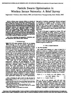
Fig. 11.
Power consumption as a function of data rate for MicaZ
and reception within the short sampling period. This means that the effect of MCU energy consumption, the main differentiator between MicaZ and TelosB, is minor. The results in this subsection have explored the dependencies of given sampling periods and forwarded packet loads on power consumption, for both the MicaZ and TelosB platforms. The next subsection explores the energy consumption of the protocols over the two platforms as a function of the useful data rate, in order to determine the best performing protocol and sleep for given data rates on each node platform. C. Optimal Configuration This section uses the term data rate to express the total useful data rate, excluding all headers, footers, and preambles. This is in order to fairly compare the three protocols, which have different packet formats and preamble lengths, against the same metric. However, the energy consumption does take into account all communication overhead as well as useful data payloads. We consider a data rate between 0 bytes/second, for nodes that have no data to send or receive, and 12,500 bytes, which corresponds to the maximum useful data rate at a level 1 node in the tree topology network in section V-A. We determine the energy consumption of all protocols at each data rate through the model in section III. For RFIDImpulse, we determine the energy consumption at each data rate for each of the three possible sleep modes M1, M2, and M3. Figure 11 plots the power consumption of the protocols as a function of data rate for the MicaZ platform. For data rates below 3500 Bytes/second, RFIDImpulseM3 has the lowest energy consumption. For data rates
14
Fig. 12.
Fig. 13.
MicaZ recommended operation modes
Fig. 14.
TelosB recommended operation modes
Power consumption as a function of data rate for TelosB
between 3500 and 10500 bytes, RFIDImpulse-M1 exhibits the best energy performance. For high data rates, 802.15.4 has the lowest energy consumption. These results serve as the basis for adaptive low power mode/protocol selection in software. As RFIDImpulse builds on 802.15.4 radios, switching between M1, M3, and basic 802.15.4 operation can be simply implemented as a cross-layer mechanism that monitors communication traffic and decides the optimal mode through the analytical model in section III. As for BMAC, it outperforms 802.15.4 for low data rates up to 1900 bytes/second, at which point 802.15.4 performs better. Figure 12 plots the power consumption of the protocols as function of data rate for the TelosB platform. Although the energy consumption trends are similar to MicaZ, we note that RFIDImpulse-M3 has the lowest energy consumption only for data rates up to 1300 bytes/second. Another notable difference is that RFIDImpulse-M2 is the best performing protocol for data rates between 1300 and 2200 bytes/second, whereas this mode is not optimal for any data with MicaZ. For data rates between 2200 and 10400 bytes/second, RFIDImpulse-M1 has the lowest energy consumption, and IEEE 802.15.4 is the best performing protocol for high data traffic. To obtain the recommended protocol and sleep mode for particular scenarios from the results in Figures 11 and 12, we use the algorithm in Figure 2. Figures 13 and 14 summarize the recommended operation mode/protocol for the MicaZ platform and the TelosB platform respectively, on the basis of data rate. For both platforms, RFIDImpulse-M3 is recommended for low data rate scenarios, since it yields the largest energy savings in sleep mode. For very high data traffic,
the recommendation is using IEEE 802.15.4, as the switching and backoff listening energy in RFIDImpulse grow for higher traffic. For medium traffic scenarios, the results indicate that RFIDImpulse-M1 performs best. The exception to this rule is for data rates between 1300 and 2200 bytes, where RFIDImpulse-M2 has the lowest energy consumption. Another notable difference for the two platform is that the threshold data rates for switching modes are lower for TelosB relative to MicaZ. In other words, Figure 13 recommends switching to RFIDImpulse-M1 for a data rate of 3500 bytes/second with MicaZ, whereas we would switch to M1 at 2200 bytes/second with TelosB. This difference stems from the reduced significance of Emcu for TelosB, which places a higher dependence of energy consumption on data rate, in the form of Er and Et . Because RFIDImpulse is still in the implementation process, Figures 13 and 14 also provide a head-to-head comparison between the widely used protocols BMAC and IEEE 802.15.4. For MicaZ, BMAC has lower energy consumption than IEEE 802.15.4 for data rates up to 1900 bytes/second, and IEEE 802.15.4 performs better for all higher data rates. For TelosB, BMAC performs better than IEEE 802.15.4 up to 1400 bytes/second. The recommendation of this head-to-head comparison is then to consider the data traffic requirements for a particular sensor network application and the target node platform. If the data rate requirements for the application are lower than the critical threshold (1900 bytes/second for MicaZ, 1400 bytes/second for TelosB), then BMAC should be used. Otherwise, the application should use IEEE 802.15.4.
15
Fig. 15.
Delay versus hop count from base for the protocols
D. Delay Implications While this section has so far explored the energy considerations for using adaptive radio sleep modes, we now briefly examine the delay implications. Figure 15 illustrates the end-to-end delay of the 5 protocols, on the basis of the model in Section III-I. As expected, RFIDImpulse delay increases for deeper sleep modes, simply due to the increase of Tα for deeper power modes. The additional delay overhead of RFIDImpulse stems from the time to perform the short acknowledgement operation to ensure the remote tag was successfully activated. The difference in delay is also higher for nodes at larger hop counts from the base, as the radio wakeup delay, as well as transmission, queueing, and backoff delays, accumulate at each forwarding hop. For a node with a hop count of six, the difference in delay between RFID-M3 and BMAC/802.15.4 is about 13 msec, representing a 15% overhead. However, for nodes at smaller hop counts, the absolute delay difference shrinks considerably. RFID-M1 has almost the same delay as 802.15.4 and BMAC, as it uses the same low power mode for the radio when idle. The slight overhead of RFID-M1 stems from the short acknowledgement operation for RFID wakeup. VI. D ISCUSSION This paper has proposed adaptive radio sleep modes as an energy optimization technique for wireless sensor networks. Because nearly all sensor network MAC protocol alternate frequently between sleep and awake states, the frequency of this state switching should dictate the appropriate sleep mode that minimizes energy consumption. In duty cycling protocols, radio state switching is highly dependent on the radio duty cycles and traffic loads, whereas it only depends on the traffic loads for wakeup radio techniques.
This paper has also provided an analytical model to conduct a comparative study of MAC protocol suitability of BMAC, 802.15.4, and the newly proposed RFIDImpulse across two popular node platforms, MicaZ and TelosB. The model also includes a simple protocol and sleep mode selection algorithm for determining the protocol/sleep mode pair that minimize energy consumption for a given traffic scenario. The study has used measured values for CC2420 radio current draw in each of its modes for a realistic comparison of the protocols. Building on the dependence of protocol performance on traffic loads, the paper has also quantitatively explored the application of adaptive low power radio sleep modes based on the level of data traffic in the network. As a rule of thumb, deeper sleep modes should be used for low data traffic scenarios as they have the lowest energy consumption for long sleep duration, and lighter sleep modes should be used for high traffic scenarios as they provide the quicker and less costly switching energy for frequent transitions between sleep and active modes. The results in Figures 13 and 14 specify the quantitative relationship between optimal radio sleep modes and data rates. The comparative protocol performance analysis has shown that RFIDImpulse-M3 has the lowest energy consumption for low traffic scenarios for both two node platforms. Medium data traffic demands a switch to RFIDImpulse-M1 to maintain minimal energy consumption, whereas 802.15.4 performs best for high data traffic. In a head-to-head comparison between BMAC and 802.15.4, BMAC performs better for low data rates, while 802.15.4 performs better for higher data rates. These results lay the groundwork for an enhanced IEEE 802.15.4-compliant MAC protocol that adapts the radio low power sleep mode in use according to observed data traffic. Sleep mode adaptation can be done on a network-wide or per-node basis through the analytical model in Section III. In a network-wide implementation of such a protocol, the base station monitors traffic flow, determines the optimal low power mode for the busiest node in the network, and broadcasts this mode to all network nodes. A per-node implementation demands that each node runs the model periodically and determines its own optimal low power mode based on its traffic load, but it also requires that nodes piggyback their current low power mode in use unto periodic beacon messages so that all neighbors are aware of low power modes in use in their neighborhood [7]. In both implementations, a sender that is aware of the low power mode in use at the receiver can send a wake-up message and wait an appropriate length of time to allow the receiver to power up its sleeping radio components before commencing
16
data transmission. The results have also highlighted the reduction of MCU energy consumption by TelosB over MicaZ, which yields about 40% overall energy savings for networks that use TelosB. The reduction of MCU energy consumption in TelosB also gives prominence to the transmission and reception energy for this platform, rendering protocol performance more sensitive to the data traffic changes, as Figures 13 and 14 confirm. Note that the results here are also applicable to most sensor node platforms that use Atmega128 or MSP430 in combination with the CC2420 radio, such as, the Phillips Aquisgrain platform. The energy consumption model in this paper also considers that applications requiring the attachment of multiple sensor types to each node can vary the sampling frequency of each of the sensors individually. For instance, a water quality monitoring application can obtain frequent periodic temperature, salinity, and Ph readings from the water. Upon detecting elevated temperatures or salinity, the nodes start sampling more energy-hungry chemical sensors frequently as well. Only nodes that have detected the event would start the chemical sensors, while other nodes keep sampling the standard sensors only. Such situations impact the relative energy consumption of nodes in the network, as the nodes that start sampling chemical sensors consume more energy. The energy model in this paper can accurately reflect this situation. It can also empower network planners to consider various choices for sensor sampling frequencies before deployment, based on the tradeoffs involved between the sensor data fidelity and the overall energy consumption of nodes. While our energy model has relied on measurements from a small sample of nodes, variations in the energy consumption of individual node components can change the appropriate sleep mode for a given traffic load. The causes of these variations include: 1) Bursty current draw: this is caused by instantaneous changes in the current draw of a specific node component. For instance, the MCU energy consumption can exhibit bursty behavior, where the sleep mode current draw of the MCU can instantaneously become double the average current. However, this bursti-ness is inherently transient, and the average current draw in a specific sleep mode is generally representative of the steady state power consumption in that mode. 2) Hardware configuration: changes in hardware settings to suit an application affect the choice of sleep mode. For instance, enabling or disabling the watchdog timer (WDT) in the MCU may
respectively increase or decrease its current draw in power down state. This may lead the MCU to consume a larger portion of the overall node energy, especially for low sampling rate applications, where the MCU energy consumption is dominant (see figure 3). As a result, the use of deeper sleep modes can become less attractive with the WDT enabled. 3) Manufacturing process: sensor node hardware is mass produced and thus there may be hardware imperfections or differences among nodes. These hardware imperfections typically cause minor variations in power consumption among nodes and maintain the relative energy consumption of various node operations. 4) Supply voltage: the supply voltage typically varies over the course of a deployment, both due to battery discharge and potentially to harvested energy. To ensure that the energy model can select optimal low power radio modes, its implementation can include a real time voltage reading of the node. By periodically capturing the present voltage value and using it for all the quantitative comparisons, the model can improve its decision on the optimal sleep mode. Because the above variations are inevitable, the energy model in this paper can readily accommodate changes in the settings or states of various node components. As long as the model accurately captures the current draw of each node component in every possible state for computing EPalpha for all available sleep modes, the model can determine the best low power mode for the radio under current traffic conditions. An interesting extension to the model is to build in dynamic component energy consumption based on varying settings and environmental changes. Our analysis of the delay implications of using adaptive sleep modes have considered uniform delay along the routing tree. In reality, queueing and collision backoff delay components are higher at critical nodes near the base station. This effect is purely dependent on the structure of convergecast topologies and not on the use of adaptive sleep modes. In fact, critical nodes may exhibit higher queueing and collision backoff delays because of the higher traffic rates in the vicinity of these nodes. If these nodes use adaptive sleep modes, they will select the light sleep mode for their operation as a direct consequence of their higher forwarding load (see Figure 13 and 14), which minimizes Tα , and consequently reduces the end-to-end delay for the packets these nodes forward. An interesting direction for future work is to implement RFIDImpulse by attaching RFID tags to the
17
external interrupt pin of sensor node MCU’s and then configuring the radio to trigger the remote tags. Supporting multiple protocol functionality, within the framework of software radio, is another interesting direction to adapt the chosen protocol to current traffic patterns in the network. Another natural next step for this work is to empirically validate radio sleep mode optimization through testbed experiments, which would further strengthen confidence in its benefits. Cross-layer dependencies in sensor networks [18] require consideration of not only energy performance based on the choice of hardware and MAC protocols, but also the delay performance and the choice of routing and scheduling protocols as well. An interesting direction for future work is to explore the inter-dependencies and between the choice of node platforms, MAC protocols, and routing and scheduling protocols. Keeping in mind that these dependencies exist, the measurement-based comparative study in this paper will hopefully serve as a guide for designers and researchers in selecting node platforms and MAC protocols that are suitable for the expected traffic requirements in their applications.
[18] R. Jurdak, Wireless Ad Hoc and Sensor Networks: A Cross-Layer Design Perspecitve, Springer-Verlag, ISBN 978-0-387-39022-2, Jan., 2007.
Raja Jurdak is a Senior Research Scientist at CSIRO since October 2008, where he leads the Sensor Networks Research Team. Previously, he was a senior researcher at the School of Computer Science and Informatics at University College Dublin. He has a PhD in Information and Computer Science at University of California, Irvine in 2005, an MS in Computer Networks and Distributed Computing from the Electrical and Computer Engineering Department at UCI (2001), and a BE in Computer and Communications Engineering from the American University of Beirut in (2000). He is also a member of the IEEE and the IEEE Communications Society. His current research interests focuses on modelling, optimization, and real world deployments of energy-efficient and highly responsive sensor networks. He has over over 40 peer-reviewed journal and conference publications, as well as a book published by Springer titled Wireless Ad Hoc and Sensor Networks: A Cross-Layer Design Perspective.
R EFERENCES [1] R. Jurdak, A.G. Ruzzelli, and G.M.P. O’Hare. “Adaptive Radio Modes in Sensor Networks: How Deep to Sleep?” In proccedings of IEEE Communications Society Conference on Ad Hoc and Sensor Networks (SECON), June, 2008. [2] R. Want Enabling ubiquitous sensing with RFID, Computer journal, IEEE Computer Society, vol. 37, pp 84-86, 2004. [3] Atmel Atmega128, http://www.atmel.com. [4] Texas Instruments cc2420 radio transceiver, http://focus.ti.com/docs/prod/folders/print/cc2420.html. [5] V. Shnayder, M. Hempstread, B. Chen, G. Werner Allen, and M. Walsh. “Simulating the Power Consumption of Large-Scale Sensor Network Applications,” In proc. ACM Sensys, 2004. [6] J. Polastre, J. Hill, and D. Culler, Versatile low power media access for wireless sensor networks, In proc. ACM Sensys, (2004). [7] R. Jurdak, P. Baldi, and C.V. Lopes. “Adaptive Low Power Listening for Wireless Sensor Networks,”IEEE Transactions on Mobile Computing. Volume 6(8):988–1004, August, 2007. [8] MicaZ Mote Platform. Crossbow Technologies. [9] TelosB Mote Platform. Crossbow Technologies. [10] A.G. Ruzzelli, G.M.P O’Hare and R. Jurdak, MERLIN: Cross-Layer Integration of MAC and Routing for Low Duty-Cycle Sensor Networks, Ad Hoc Networks journal, Elsevier, February, 2008. [11] L. Gu and J.A. Stankovic, Radio-Triggered Wake-Up Capability for Sensor Networks, Proceedings of the 10th IEEE Real-Time and Embedded Technology and Applications Symposium (2004). [12] Tag Sense: RFID and Wireless Sensing http://www.tagsense.com/ [13] P. Skraba, Hamid Aghajan, Ahmad Bahai, RFID Wake-up in Event Driven Sensor Networks, Technical report, U.C. Berkeley, 2001. [14] A.G. Ruzzelli, R. Jurdak, and G.M.P. O’Hare, On the RFID wake-up impulse for multi-hop sensor networks, In proceedings of (SenseID) Workshop at (ACM SenSys 2007), Sydney, Australia. November, 2007. [15] A.G. Ruzzelli, P. Cotan, G.M.P. O’Hare, R.Tynan, and P.J.M Havinga, Protocol assessment issues in low duty cycle sensor networks: The switching energy, In Proc. IEEE (SUTC2006), Taichung, Taiwan. June, 2006. [16] IEEE 802.15.4 MAC/Phy standard for low-rate wireless personal area networks (LR-WPAN’s) http://www.ieee802.org/15/pub/TG4.html [17] TagSense Inc. ZT-10 Active RFID Tag. available: http://www.tagsense.com/ingles/products/products/ZT-10-tag-v4-5.pdf
Antonio G. Ruzzelli is a postdoctoral researcher at University College Dublin (UCD), School of Computer Science and Informatics, where he obtained his Phd in 2008. His research addresses wireless communication protocols for ad-hoc and sensor systems with an emphasis on interoperability issues, medical applications and energyefficiency in buildings. Previous affiliations include Philips research Eindhoven (NL), University of Twente (NL) and University of Ferrara (IT).
Gregory O’Hare was the Head of the Department of Computer Science at University College Dublin (UCD) 2001-2004 Prior to joining UCD he was on the faculty of the University of Central Lancashire and the University of Manchester. His research interests are in the areas of Distributed Artificial Intelligence and Multi-Agent Systems (MAS), and Mobile and Ubiquitous Computing, Autonomic Systems and Wireless Sensor Networks. O’Hare is a Fellow of the British Computer Society, a member of the ACM, AAAI and a Chartered Engineer.