Robtep 2010
1
RAPID PROTOTYPING USING ROBOT Jacek LEWANDOWSKI, Tadeusz MIKOLAJCZYK
Rapid prototyping using robot Annotation: Paper shows the research of robot using to rapid prototyping of large models. Special controlled PC system was made to polyurethane foam injection. First probe of using this system to build model was shown. Keywords: robot machining, rapid prototyping, polyurethane foam
INTRODUCTION Rapid prototyping (RP) is the unique and the fastest technology of creation the models of any object that can be later released to consumer market. RP is carried out using special prototyping machines that are capable of creating rapid prototyping models very fast from several hours to several days, depending on the complexity of the object produced. RP technology has many benefits and advantages, such as: 1. irrespectively of the type of the object being produced, the process takes less time than any other technology will ever do, 2. used materials can vary and even be mixed, depending on the desired result. Those materials can be RP wax, metals, liquids, powders, etc. They can be used separately or mixed in order to get the best result, 3. the economy provided by RP technology is great. RP processes is based on the CAD that is deciphered as computer-aided design. The machine assisted by a computer uses 3D graphical model of the product to produce a real object. RP machines are sometimes called 3D printers. Paper describes an idea of industrial robots using to RP. Example of using IRb60 robot for rapid prototyping large scale models with polyruethane foam was shown.
INDUSTRIAL ROBOT USING TO RAPID PROTOTYPING IDEA Industrial robots are used in many ranges of contemporary manufacturing [1-5,7-11]. The kinematics possibilities of robots [1,3] and applied software [10] make possible their use in the different jobs especially in machining with special tools using [1, 3-,5,7-9,11]. These solutions are more cheaper than conventional numeric control machine using. Kinematics possibilities of robots, frequently equipped in more than 5 axes machine-tool, enabled its geometric and kinematics flexibility tools[5] for shaping and finishing. Surface processing with robots are programmed using CAD model of its geometry [9,10]. An idea of robot using to RP depend on use of kinematics of robots to build model with using special medium (fig. 1). We are searching for low cost medium to adapt it to our RP system. To large scale model we chose the polyurethane foam hardened by water.
IRB60 RAPID PROTOTYPING SYSTEM IRb 60 industrial robot modernized with computer use (fig. 1) [6] was applied in this work. Original IRb60 control system was saved. It was realized based on existing robot control system. In proposed robot control system, manual buttons of robot control panel was used. Approachable buttons make possible control of: velocity, robot rotation, robot arm perpendicular moving, robot arm horizontal moving, head inclination, head rotation, gripper use. In worked out modernized industrial robot control system special interface [6] connected to computer’s LPT communication port was used. Proposed conception does not disturb existing control arrangement MSc, Jacek Lewandowski, graduate of University of Technology & Life Sciences, POLAND, Bydgoszcz, DSc, Ass. Prof. Tadeusz Mikolajczyk, University of Technology & Life Sciences, POLAND, Bydgoszcz, phone:+48 52 3408758,
[email protected] Recenzent :
prof. Ing. Mikuláš Hajduk, PhD., TU v Košiciach, SjF, (SK)
2
Robtep 2010
and it creates the completely new possibilities of use obsolete robot. There is no feedback in modernized control system, but it is possible in single steps mode.
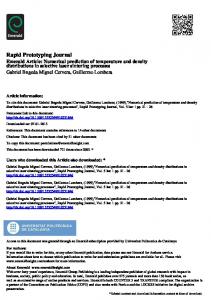
Medium aplicator
Manual panel Main control system Interface
Prototype
Fig. 1. An idea of robots using to rapid prototyping Robot head was equipped in special polyurethane foam injection system controlled by PC (fig. 2).
Fig. 2. Controlled PC polyreuthane foam injection system According to the existing techniques used in the method similar to the method of FDM (the imposition of successive layers cladding). Foam injection system was controlled using special USB digital output interface. Built computer-controlled system (fig. 1) overlap with the foam injection system (fig. 2). This applicator has been fitted with a control loading of material through the use of screw-driven DC motor and secured limit switches. Control valve is carried out using a USB card with additional transmitters relay. Special software in VB6 environment was made to control system. This software makes possible two way of robot control: manual and sequential. Steering in sequential mode based on instructions in special file. By software we may control all co-ordinations of robot movements. Using panel applicator shown in figure 3, you can: 1. start, stop control head move, 2. select time of opening and closing injection system, 3. choose the interval between superimposed layers, 4. enter number of layers, 5. show view of the currently applied layer using the camera , capture images. The implementation of the incremental development of a single piece of polyurethane foam used Titan's SELLEN pistol, which is cured under the influence of moisture from the air or ground.
Robtep 2010
3
The polyurethane foam is characterized by the following parameters [12]: 1. temperature from -10 ° C to 25 ° C, 2. density 20-25 kg/m3, 3. change in linear dimensions at 40 ° C max 5%, 4. compressive strength min 60 kPa, 5. coefficient of thermal conductivity 0.040 W max / mK, 6. thermal resistance from -40 ° C to +100 ° C, 7. volume after injection 500 ml-25 l, 750 ml-35l. The conducted tests of worked out arrangement confirmed the possibility of injection polyreuthane foam in robot IRb60 machining space.
Panel of DO control
Panel of robotts manual control
Panel of rapid prototyping process control
USB camera view on-line & freeze
Fig. 3. Form of rapid prototyping using robot system
RAPID PROTOTYPING EXPERIMENTS Developed device on the robot's head was mounted and used to shaping. Impact tests were carried out speed the head move and the opening level of injection system on the process of overlapping polyurethane layer. The modification also attempts to shape the working tip of the imposition of polyurethane. Studies conducted dimensions imposed by layer using a 2D scanner.
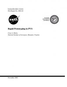
v mm/s
150 100 50 0 0
500
1000
1500
time ms Fig. 4. Effect of time opening the injection system on the polyurethane foam outflow speed
4
Robtep 2010
width
height
Fig. 5. Sample chart the time influence on expand the single layer dimensions View of shaping elemntary layers was shown on figure 4-6. Relationship between the polyreuthane foam injection conditions and shape mistakes and size of a single layer was found. Stabilization of the dimensions of a single layer of foam under the conditions used was applied after a relatively long time (fig. 5). Obtained in a test model is characterized by a distinct texture of individual layers (fig. 7). Proved convenient to use rectangular nozzle. Developed RP technology which is characterized by a distinct surface texture can sometimes require additional surface detail machining. Foam was used to produce models with 2535 liters volume from one package. Due to the stability conditions of administration and the possibility of the formation of bulky products, it is appropriate to use the installation of twocomponent foam. This foam is characterized by the faster hardening time.
1400ms
1300ms
1200ms
1100ms
1000ms
Fig. 6. Effect of injection system time opening on the sizes polyurethane foam single layer
Fig. 7. Cross-section of multiple layers
900ms
Robtep 2010
5
CONCLUSIONS This paper describes a new idea of the robot application in manufacturing. In presented research was used robot equipped with PC controlled polyurethane foam applicator. This is a new idea of rapid prototyping large scale models. On the basis of preliminary tests identified the possibility of using this original technique to rapid prototyping. Beacause of this kind of rapid prototyping can build model with low gravity material, this technique is especially convenient for the large-size models formation. The resulting model can be subjected to additional surface machining. It is appropriate to apply this technique, especially with chemically hardened polyurethane.
REFERENCES [1] CHEN Y. H., HU Y. N.: Implementation of a Robot System for Sculptured Surface Cutting. Part 1. Rough Machining. International Journal Advanced Manufacturing Technology, v. 15, 1999, 624-629, ISSN 0268-3768 [2] HONCZARENKO J.: Roboty przemys owe. Budowa i zastosowanie. WNT, Warszawa, 2004, ISBN 83-204-2929-3 [3] HU Y. N., CHEN Y. H.: Implementation of a Robot System for Sculptured Surface Cutting. Part 2. Finish Machining. International Journal Advanced Manufacturing Technology, v. 15, 1999, 630-639, ISSN 0268-3768 [4] LATOS H., MIKOLAJCZYK T.: Surface Shaping with Industrial Robot. 1st International Conference “Optimization of the Robots and manipulators” OPTIROB-2006, University “POLITEHNICA” of Bucharest, ROMANIA, Faculty IMST, Department MSP, Predeal, 2006, 265-269, ISBN(10) 973-648-572-2 [5] LATOS H., MIKOLAJCZYK T., Virtual Aid Design of Geometric and Kinematics Flexible Tools. XII Workshop on Supervising and Diagnostics of Machining Systems. Virtual Manufacturing, Karpacz, 2001, 145-152, ISSN 0867-7778 [6] MIKOLAJCZYK T.: Modernization of IRb60 Industrial Robot Steering System. The 2nd edition of the international conference Optimization of the Robots and Manipulators, OPTIROB’2007, Predeal Romania, University “POLITEHNICA” of Bucharest, Faculty IMST, Department MSP, pp 149-152, ISBN 978-973-648-656-2 [7] MIKOLAJCZYK T.: The Robot Machining System with Surface Shape Active Control. The 2nd edition of the international conference Optimization of the Robots and Manipulators, OPTIROB’2007, Predeal Romania, University “POLITEHNICA” of Bucharest, Faculty IMST, Department MSP, pp 205-209, ISBN 978-973-648-656-2 [8] MIKOLAJCZYK T.: Robot Application to Surface Manufacturing. ROBTEP 2008, Acta Mechanica Slovaca, Kosice 2-A/2008, 387-394, ISSN 1335-2383 [9] www.delcam.com/powermill/simulation.htm [10] www.irbcam.com [11] www.robots.com.contacts.htm [12] www.sellena.com.pl