Missing:
Rapid Prototyping with Metals: A Review of Technology and Associated Material Properties
Christopher B. Williams
ME 6796 – Midterm Report November 4, 2003
1
THE TRANSITION OF RAPID PROTOTYPING MANUFACTURING: THE NEED FOR METAL RP
TO
RAPID
Rapid Prototyping (RP) is the term given to a set of processes that can quickly fabricate any given three-dimensional object directly from a CAD file via the additive deposition of individual cross-sectional layers of the part. Although there are several RP technologies with different working principles, they all produce parts using similar steps: • a three-dimensional CAD file is “sliced” into two-dimensional contours, representing cross-sectional layers of the object • this information is sent to a RP machine, where the build plan is generated • starting with the bottom layer, a cross-section of the part is deposited (usually via the rastering of the 2D contour with several line deposits) • the part is lowered one layer thickness (typically via a build elevator), and the next layer is deposited; this process repeats until the entire part is deposited. Since it is a layer-based additive manufacturing method, designers using RP technology have the power to build almost any conceivable geometry. This opportunity is one reason for the emerging interest of transforming this technology from the realm of creating prototypes to a paradigm of its use as a machine for manufacturing. This research push for Rapid Manufacturing (RM) is derived because of the numerous benefits of using this additive manufacturing technology when compared to traditional hard tooling alternatives: • Rapid prototyping gives the manufacturer the ability to create multiple, different geometries in a single build. A traditional casting process would require the creation of a separate mold for each desired geometry. The RP engineer is capable of producing many different parts in one build by simply adding each of their 3D CAD models to the build file. Unless the parts are of different materials, many parts can be manufactured in one common build. • Rapid prototyping does not require a change in tooling for the creation of different geometries, hence it’s acknowledgement as a “tool-less” machine. Each technology uses a central method in which to “draw and fill” the cross section of each part (i.e., Stereolithography’s UV laser and photo-curable resin, or Fused Deposition Modeling’s heated nozzle and polymer filament). With this one working principle, an RP machine is capable of making any conceivable geometry without a need to switch tools, thus eliminating the excess costs and downtime associated with production setup. • The desire to created customized geometries with rapid prototyping does not require extra skilled operator input. To manufacture different geometries with RP technology, the operator is simply required to upload the CAD file and orient the part in the build. Despite these listed benefits, the use of many of the commercially available RP technologies in industry is not feasible due to their limited use of functional or standardized working materials. As can be observed in Table 1, the majority of RP technologies produce prototypes made of some certain, and often proprietary, polymer.
1
Table 1 – Comparing the Materials of Rapid Prototyping
Technology StereoLithography (SLA)
Working Principle UV laser is selectively scanned onto photo-sensitive polymer
Fused Deposition Modeling (FDM) Selective Laser Sintering (SLS)
Plastic filament is extruded through heated nozzle Using a heated laser to sinter together particles
Laminated Object Manufacturing (LOM)
CO2 laser is used to cut crosssections out of layers of paper; layers are thermally fused together Printer head deposits molten wax onto bed of starch Similar to an ink-jet printer, several print heads deposit beads of wax
Three Dimensional Printing (3DP) Multi-Jet Modeling (MJM)
Material Liquid UV photopolymers; highly toxic Wax, ABS, elastomers Polycarbonate, Nylons, elastomers, ceramics, some metals Paper; similar to wood
Wax and starch, fragile and powdery Wax
This issue of limited material selection is identified as one of the key reasons why rapid prototyping has yet to make a major advance towards rapid manufacturing. It has been a goal of many researchers in the past five years to overcome this limitation through the development of RP processes that are capable of producing metallic components. The development of a RP technology capable of creating metallic parts would herald significant advantages in manufacturing and design: • Objects created using RP will no longer be limited to prototypes of fit and form, but will be useful as functional prototypes; the design iteration will be greatly shortened as prototypes with materials extremely similar to the actual manufactured part will be used for analysis without expensive tooling • RP will no longer be limited to the production of prototypes; instead actual parts will be able to manufactured straight from the machine • For large production runs where manufacturing through RP would be too slow, the technology could be used to create tooling (molds, inserts, etc.) for the production process • Due to the ability to manufacture several different parts in one batch, customized products could easily be made • There also exists an opportunity to create functionally graded materials; RP’s nature of additive fabrication enables itself to the placement of different materials in specific places throughout a geometry • Geometrically tailored components optimized for high strength and low mass would also be able to be manufactured. As can be seen, there is a large motivation to overcome the materials limitation of current RP technologies. In this paper a review of several current metal RP technologies and the material properties of their respective parts is presented. In Section 2, a quick overview of the technologies is presented through a description of the different deposition
2
working principles. Three of the technologies, Laser Engineered Net Shaping, Selective Laser Sintering, and Multiphase Jet Solidification are discussed in detail in Sections 3, 4, and 5 respectively. In Section 6 several other metal RP technologies are quickly discussed, while closure is offered in the final section of this paper.
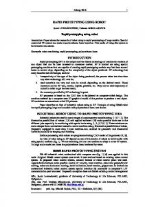
2 RP METALTECHNOLOGY OVERVIEW Although research in the rapid prototyping of metallic components is relatively new (successful selective laser sintering and cladding of metallic powders were first described in the early 1990s), there are currently numerous different directions in metal RP technology development. These technologies can be grouped according to their fundamental metal deposition working principles as seen in Figure 1.
METAL RP Indirect Selective Laser Sintering (SLS)
3D Printing
Laminated Object Manufacturing (LOM)
Laser Sintering SLS (direct)
Direct
Stereolithography (SLA)
Laser Based
Non-Laser Based
Fused Deposition Modeling (FDM)
Multiphase Jet Solidification (MJS)
Laser Cladding Laser Engineered Net Shaping (LENS) Direct Metal Deposition (DMD)
Laser Binding
Selective Laser Melting (SLM)
SLS (indirect)
Ultrasonic Object Consolidation (UOC)
Laminated Object Manufacturing (LOM)
Optoform Paste
Figure 1 – Hierarchical Classification of Metal RP Technologies
2.1 Indirect vs. Direct Fabrication As can be seen, the first distinction of metal RP technologies lies in the manner in which the metallic part was generated. Indirect fabrication is the use of a RP machine to generate inserts or molds for the creation of metallic parts. Also known as Rapid Tooling, indirect fabrication techniques involve creating a mold out of a standard RP material from which several hundred parts can be injection molded. Usually the RP molds must have an epoxy affixed to them in order to withstand the high temperatures of molding. Other indirect fabrication techniques involve the use of a rapidly prototyped part as a pattern for the creation of a mold.
3
Direct fabrication, on the other hand, is the use of a RP machine to create a functional metallic part. Many different and new technologies have been created in order to tackle this large problem. This portion of the metal RP research is the focus in this paper. 2.2 Direct Fabrication: Laser vs. Non-Laser Based Simply stated, direct metal RP fabrication techniques can be divided into laser based and non-laser based technologies. Non-laser based technologies involve the selective deposition of metal material. Currently, Multiphase Jet Solidification (MJS) is the only non-laser based technique being developed. It is very similar to Stratasys’ Fused Deposition Modeling in that it selectively deposits its preheated material through a nozzle. MJS is discussed in more detail in Section 5. Laser based fabrication involves the use of a laser to selectively join the metallic material. As can be seen in Figure 1, this can be done through sintering, cladding, or binding. 2.3 Direct Fabrication Via Laser: Sintering, Cladding, and Binding Fabrication of metallic components via laser sintering involves the use of a highpowered laser to selectively melt the surfaces of pure metallic powders in order to create a “green” part. The part typically undergoes subsequent infiltration in order to create a fully dense part. This type of fabrication is discussed in Section 4 in the context of indirect Selective Laser Sintering (SLS). Laser cladding is analogous to 3D welding. Using an extremely high-powered laser, metal particles are completely melted and selectively deposited on a substrate. This process is detailed in Section 3 through a discussion of the Laser Engineered Net Shape (LENS) process. Finally, laser binding generally involves the use of a laser to bind a second phase in order to hold the metallic particles together. These parts are then required to undergo a debinding stage and a sintering stage. This final classification of RP metal fabrication techniques is illustrated in Section 4 through an investigation of direct Selective Laser Sintering. The remaining RP metal technologies listed in Figure 1 are briefly described in Section 6.
3 LASER ENGINEERED NET SHAPING (LENS) 3.1 Working Principle of LENS The working principle of the LENS process is the use of a laser to selectively clad metallic powder. A schematic of the process is provided in Figure 2.
4
Figure 2 – Laser Engineered Net Shaping Schematic (Keicher, 1998) and Photograph (Weerasinghe et al., 1983)
A high-powered laser beam (typically >300W Nd:YAG) is focused on a metal substrate to create a molten weld pool. Metallic powder is then injected into the weld pool by an inert carrier gas. The powder is melted in the pool; as the laser passes by the deposit is quickly cooled, leaving behind a thin line of metal (Keicher, 1998). The substrate is moved relative to the laser beam in order to deposit thin metallic lines with a finite width and thickness. Rastering of successive cross-sectional layers is done as the laser-focusing lens and powder delivery nozzle are raised along the z-axis. Once the part is complete, the substrate is removed by machining or by dissolving with chemicals. In addition to the basic hardware (laser, powder delivery apparatus, and CNC table), the system also consists of control system hardware and a cooling system for the powder nozzle. The cooling system is used for the powder nozzle because it is exposed to a thermal load by scattered and reflected laser radiation. Control system hardware includes sensors and CCD cameras in order to provide online control – an integral part of the process (Boddu et al., 2001). The major strength of the LENS process is its ability to deposit a multitude of materials. Since the material deposition relies only on the feeding of a powder or wire, it is relatively simple to use multiple kinds of materials. Currently titanium, nickel, cobalt, steel, and aluminum can be deposited with LENS. In fact, recent research has shown that LENS is capable of manufacturing binary functionally graded materials (Hedges et al., 2002). The LENS process does have some weaknesses, however. While LENS is lauded for its planar accuracy (+/- 005”) and its ability to manufacture thin-walled parts, it is only capable of producing “near net shape” components because of its poor accuracy in the build direction (0.015”). Also, unlike standard RP technologies, LENS does not have the ability to generate support structures for complex geometries featuring overhangs. As such, the geometry able to be created by the LENS process is limited; the maximum angle achieved in a single width deposition is 30o, and about 15o for solid parts (Griffith et al., 1996). However, research on the development of a multi-axis LENS machine is underway (Hedges et al., 2002). The deposition rate of LENS is quoted as 0.5 cubic inches per hour.
5
3.2 Material Properties of Parts Produced by LENS Mechanical properties of tensile specimens from the LENS process are presented in Table 2. Table 2 – Mechanical Test Data from LENS Manufactured Tensile Specimens (Keicher, 1998) Plane Orientation with Respect Ultimate Strength Yield Strength Elongation to Tensile Direction (mesh size) (MPa) (MPa) (% in 2.54 cm) 316 SS Perpendicular (-325) 793 448 66 316 SS Perpendicular (100/325) 793 448 51 316 SS Parallel (-325) 807 593 33 316 SS Anneal bar (Standard) 586 241 50 625 Parallel (100/325) 931 634 38 625 Perpendicualr (100/325) 931 517 37 625 Annealed bar (standard) 834 400 30
As can be seen in the above table, the LENS parts had yield strengths significantly better than typical annealed wrought material. In addition, the ductility of the specimens was as good or better than the annealed wrought material (with one exception). It should be noted, however, that the concurrent increase in strength and ductility suggests the presence of residual stress in the parts. It is believed that the improved material properties obtained are a direct result off the fast cooling rates (104 Co/second) and resultant grain size of the LENS process. Metallographic analysis of several materials using the LENS technology has shown substantial reductions in grain size as compared to like compositions in wrought form. A visual comparison of 316 steel grain structures is offered in Figure 3. A comparison of grain size measurements of LENS specimens and wrought material is given in Table 3.
Figure 3 – Photomicrographs Contrasting Differences Between (left) wrought 316 SS Grain Structure; and (right) LENS Deposited 316 SS Grain Structure (Hedges et al., 2002) Table 3 – Grain Size Comparison of LENS and Wrought Materials (Hedges et al., 2002)
Grain Size, H13 Tool Steel (µm) Grain Size, 316 SS (µm)
LENS Specimen 3 6
6
Wrought Material 26 60
As with any RP technology in its infancy, the majority of research concerning the LENS process is on optimizing the process parameters in order to receive reliable and repeatable deposits. As can be expected, the quality of the part has a large dependency on several process parameters: • Laser Properties o At larger wavelengths metallic materials have large reflectivity; consequently, laser cladding of the metals is fairly difficult. This is one reason why the Nd:YAG lasers are used (wavelengths of 1.06 µm); lasers with larger wavelengths (i.e., CO2 10.6 µm) experience significant reflection losses. o Laser energy intensity, I, is related to laser power, P, workpiece feed rate, P V, and diameter of the laser spot, d, by: I = (Laeng et al., 2000). Vd Fundamentally, this relates the scan speed of the laser across the substrate to laser power – the lower the scan speed, the more power needed to deposit materials. o As shown in Figure 4, for a given amount of laser power, cladding is feasible only within a region restricted by dilution limit, clad width geometry, and a power limit. For a given powder feed rate and spot size, too much power will result in a dilution problem – causing insufficient layer thickness, poor inter-layer bonding, and defects. Likewise, too little power will cause a porosity problem.
Figure 4 – Feasible Operating Region for Laser Cladding With Blown Powder (Weerasinghe et al., 1987)
•
Particle properties: Powders smaller than 50 microns can be blown away by the carrier gas during deposition; however, large powder particles cannot be melted properly. As may be expected, smaller powder particle size yields a better surface finish (Griffith et al., 1996). 7
• •
Powder temperature: If the powder is too cold as it hits the surface of the melt pool, inadequate fusion with the workpiece will occur; if the powder is too hot, the powder stream could ionize, forming plasma (Laeng et al., 2000). Deposition overlap: The amount of overlap between clads is another critical factor in the LENS process, as it is directly related to porosity and surface finish. As can be seen in Figure 5, when beads are produced with high laser energy intensity, air is caught between the clads, thus leaving pores. A benefit of overlapping arises from the tempering of previous deposits by successive passes, thus relieving residual stress (Boddu et al., 2001).
Figure 5 – Inter-run Porosity Clad: Stainless Steel 316 (Weerasinghe et al., 1983)
• •
Melt pool temperature: the Heat Affected Zone of the laser must be carefully watched; high temperatures can cause defects, thermal distortion, and high residual stresses upon cooling that may cause cracking. Layer thickness: As more and more layers are deposited, the energy density of the laser beam is lowered as it becomes more defocused; this can lead to porosity because the laser can no longer fully melt the material, which weakens its bond with the previous layer. The layer thickness and the energy density of the laser beam are the most important parameters: as the energy density is lowered, the layer thickness is less because there is less energy per unit area to melt the powder (Mazumder et al., 1999).
3.3 Advantages and Disadvantages of the LENS Process To summarize the LENS process, and the laser cladding process in general, the following list of advantages and disadvantages is presented. Advantages • Capable of depositing numerous materials • Good accuracy in build plane; capable of producing thin walls and ribs • Material properties are improved over casting • 50% material usage (compared to 5-20% for standard forging and machining) • Capable of producing functionally graded materials • 100% dense parts Disadvantages • Poor accuracy in growth direction
8
• • •
Poor surface finish Cannot to do complex geometry In need of more specialized process control for reliable deposits
4 SELECTIVE LASER SINTERING (SLS) 4.1 Working Principle of SLS Looking back to Figure 1, it is observed that Selective Laser Sintering (SLS) is listed under three different categories of RP metal fabrication: as an indirect fabrication method, as a laser sintering method, and as a laser binding method. This technology is one of RP’s most robust. This technology’s working principle is the use of a C02 laser to fuse and sinter metallic powder one layer at a time (see Figure 6).
Figure 6 – Schematic of Selective Laser Sintering Technology (Greulich, 1997)
The process involves sweeping a layer of metallic powder over the build bed, selectively scanning the laser over a cross-section and sintering the material, and then lowering the bed and recoating. SLS has a unique advantage over other RP techniques, as it has no need for specific structural material – the unsintered powder surrounding the powder provides sufficient support. SLS is typically performed in an inert atmosphere to prevent the forming of oxides. Also the powder bed is preheated to prevent significant warping from the inherent heating and cooling of different layers during manufacture (Carter et al., 1993). Both SLS and LENS processes are similar in that they involve laser melting of powder particles. In LENS, particles are completely melted and form a melt pool. In SLS, however, only the particle surfaces are melted, which enables particles to fuse together (Figure 7).
9
Figure 7 – Neck Formation After Solid State Selective Laser Sintering of SS Powder Particles (Kruth et al., 2003)
SLS is used primarily for its nylon and elastomer prototypes; however, a lot of research has been done on using the machine to manufacture metal parts. SLS parts can be used as mold patterns. Also, a proprietary SLS material, RapidToolTM, allows for the manufacturing of injection tool molds straight from the SLS machine, thus offering two opportunities for the indirect fabrication of metal. Commercially only one material from DTM’s SLS machines, LaserFormTM – a type of stainless steel, is available for the direct fabrication of metallic components (Systems, 2003). EOS, a German company, sells a sintering machine that is capable of producing metal parts – the EOSINT M. This machine works on the same principles of DTM’s SLS machines, and is capable of making a bronze-nickel alloy. 4.1.1 Indirect SLS Indirect SLS is one technique of directly fabricating metal parts with this technology. In indirect SLS, the working material is a polymer coated metallic powder (typically a 5 µm coating). This second phase material is selectively melted by the laser and effectively binds the metal particles together to make a green part. The green part is then infiltrated with a water soluble polymer to enable a stepwise debinding of the green part (which causes some shrinkage). In a final step, the part is sintered in combination with the infiltration of another metal material (usually copper). 4.1.2 Direct SLS In direct SLS, the working material is a two-phase metallic powder. Early attempts to laser sinter metal powders with only a single component resulted in a “balling effect,” specifically the formation of spherical particles in the molten metal (Greulich, 1997). The second-phase metal has a lower melting temperature and is therefore the binder material. The laser then selectively sinters the powder mixture to make the metallic component. Since there is no polymer in this powder mixture, the debinding step is no longer necessary. Typically, a sintering process is needed to fully densify the part.
10
4.2 Material Properties of Parts Produced by SLS 4.2.1 Indirect SLS The polymer-coated metallic powders used in this type of SLS ensure that the laser radiation hitting the powder particles is preferentially absorbed by the binder material that is to be melted (and not the metallic, structural material). Moreover, a more effective and homogeneous bonding of the structural particles is realized since the binder material already surrounds all structural particles (Kruth et al., 2003). Shrinkage caused by debinding is 4.5% in the horizontal and 5% in the vertical direction, which can affect the accuracy of a part. After debinding, sintering, and infiltration, the resulting material is 60 vol.% steel and 40 vol.% copper. It has a tensile strength of about 475 MPa and a yield strength of 255 MPa (Greulich, 1997). In Figure 8, the microstructure of a part undergoing this process (from powder to initial sintering to debinding, infiltration, and final sintering) can be observed.
Figure 8 – Steps in Aluminum SLS: a) powder, b) green resin bounded skeleton, c) after infiltration (Kruth et al., 2003)
4.2.2 Direct SLS The direct SLS of EOS (a German RP company) uses a bronze/nickel powder containing a small amount of copper phosphorous (Cu-P). This material, called Elux, acts as the low melting phase and liquefies when the powder is sintered by the laser. After initial sintering, a porous part is produced with a density of 70% of theoretical (Greulich, 1997). In the final step, the part is infiltrated with a high temperature epoxy (shown in Figure 9).
11
Figure 9 – Cross Section of a Laser Sintered Sample Infiltrated with Metal (lighter areas); the Darker Areas are the Matrix (Greulich, 1997)
As can be seen, there is no residual porosity remaining. The infiltration step not only improved the mechanical properties, but it also assisted in smoothing the surface of the part (because of the capillary forces, the infiltrant fills the inner pores from the bottom to the top). It should be noted, however, that not all the powder particles are molten (Figure 10).
Figure 10 – Micrograph of Multiphase Steel Powder (Kruth et al., 2003)
The improvement in porosity and surface quality from smaller grain sizes and shotpenning is illustrated in Figure 11.
12
Figure 1 – DMLS Direct-Metal 50V-2 Grain Size 50 mm, Porosity 10-15%: (left) Before and Right After Shot-Penning; (right) Cross Section and Top View (Kruth et al., 2003)
Finally, important mechanical properties of commercially available SLS metal materials are provided in Table 4. Table 4 – Commercial SLS Metal Powder Systems and Their Mechanical Properties (C=Copper, B=Bronze, E=Epoxy Resin) (Kruth et al., 2003)
13
4.3 Advantages and Disadvantages of Selective Laser Sintering Indirect sintering has the advantage that only the binder material needs to be melted, most of the time at a low temperature, allowing manufacturing of metallic parts using conventional plastic sintering machines. However, the workpiece must be debinded and infiltrated, causing loss of accuracy and prolonging the time needed for manufacture. Direct sintering is aimed at melting the chosen material during the SLS process directly, eliminating the need for debinding. However, since processes currently industrially available leave the parts with a porosity of about 70%, infiltration is still necessary to achieve full density. Another problem related to the direct sintering of metallic powders is shrinkage and induction of thermal stress resulting in distorted and curled parts. Advantages and disadvantages of the SLS process in general are offered below. Advantages • Accurate deposition both in-plane and in growth direction • Net shape parts • Capable of generating complex shapes without the need to remove support structures Disadvantages • Plagued by porosity • Some shrinkage; part accuracy suffers • Only a few metal-like substances; proprietary metal compounds 5 MULTIPHASE JET SOLIDIFICATION (MJS) 5.1 Working Principle of MJS The working principle of Multiphase Jet Solidification (MJS) is shown schematically in Figure 12.
Figure 12 – Working Principle of the MJS Process (Gruel et al., 1997)
14
A powder-binder mixture is passed through the machine as feedstock, where it is first heated above its solidification point to achieve a suitable viscosity. It is then squeezed out of nozzle by a pumping system and deposited layer by layer (the deposition head unit is mounted on a xyz-table that is controlled by a computer system). The molten material solidifies once in contact with the platform or the previous layer due to the decrease in temperature and pressure. The contact of the liquefied material leads to partial remelting of the previous layer and a good bonding between the layers. Critical process parameters to successful deposition are the speed of the deposition nozzle, and the flow rate of the material. In order to make a functional metal part, the green part made via the deposition (typically 50-70% percent volume solid material) must then undergo a debinding step and a sintering step, as shown in Figure 13.
Figure 13 – Schematic of the MJS Process Chain (Gruel et al., 1997)
The debinding stage occurs with a solvent or through thermal decomposition, thus transforming the green part into a brown part. After the subsequent sintering, the final part density is 95-98%. 5.2 Material Properties of Parts Produced by MJS Materials succsefully tested with MJS include 316L, M4T2, FENi, Ti, Stellite (CoCr-Mo), and Sic (Kupp et al., 1997). One large advantage with MJS is that is able to use a broad range of materials; due to its similarities with metal injection molding (MIM), researchers are hoping that the long materials list of this successful technology will be carried over to MJS. The main restrictions for materials is that they must have a suitable viscosity, around 10 to 200 Pa.s, and a binder melting temperature of less than 200 Co (Gruel et al., 1997). A comparison of material properties between MIM and MJS parts is provided in Table 5.
15
Table 5 – Comparison of MIM and MJS 316L Parts (Kupp et al., 1997)
Process and Material MIM 316L, typical values MJS 316L
Density (% of theoretical) 95-99.8
Ultimate Tensile Strength (MPa) 450-520
97-99.3
480
It should be noted that the powder-binder often observed in MIM is not a problem with MJS due to the lower velocity with which the material exits from the nozzle (Gruel et al., 1996). The homogeneous structure and good bonding between the layers found in MJS is illustrated through the investigation of its microstructure, provided in Figure 14.
Figure 14 – Optical Micrographs from Parts out of Ceramics (Gruel et al., 1996)
The largest problem with this technology is the large amount of shrinkage (10-16%) that arises from the sintering stage. This obvious difference in the size of the parts is shown in Figure 15.
Figure 15 – Parts Out of SiC Produced by the MJS Process (Gruel et al., 1996)
In order to avoid this shrinkage, the brown part can be infiltrated with liquid metal. The infiltrant must be harmonized with the matrix material with regard to melting temperature, wetting behavior, etc. This technique also improves the mechanical properties of the final part (Gruel et al., 1996).
16
The achievable accuracy of the green parts is +/- 0.2mm. The accuracy of the final part depends to a large extent on post processing, e.g. debinding and sintering. The maximum wall thickness is limited to 15mm due to the debinding step. Fundamentally, the surface quality depends on the layer thickness. The layer-based fabrication process inherently leads to rough surfaces (the stair-step effect), however, the green parts can be easily machined or sanded to a smooth surface finish before sintering (Gruel et al., 1997).
6 OTHER METAL RP TECHNOLOGIES In this section the technologies yet to be presented from Figure 1 are briefly discussed. The majority of these technologies are in their infancy; as such, their accompanying literature focuses on the working principle and not on the associated material properties. 6.1 3D Printing This technology involves the use of a printer head to selectively deposit a binder polymer over a bed of metal powder. The selectively bound part, when later removed from the bed, is a relatively low-density (about 50%) “green” part. The green part is then subsequently fired and infiltrated to make a dense metal part. Stainless steel-bronze parts have been made with this technology (Feenstra et al., 2003). 6.2 Shape Deposition Manufacturing (SDM) This technology combines laser cladding (as seen in the LENS process) with subtractive machining. A laser is used to melt powdered metal in order to deposit metal; a milling machine is then used to create a near-net shape component. This process has been proven to successfully make functionally graded materials (Fessler et al., 1996). 6.3 Laminated Object Manufacturing (LOM) This technology has been traditionally used to cut stacks of paper layers with a laser. Recent research from Japan shows interest in using the same technology to create metal parts from several layers of cut sheet metal (Nakagawa, 1985). 6.4 Ultrasonic Object Consolidation (UOC) This technology utilizes solid-state joining techniques to deposit layers of tape to form solid aluminum parts. The process involves depositing several layers of aluminum tape, followed by a trimming step in order to produce near-net shape parts (Solidica, 2003). The process is extremely fast but is currently limited to aluminum. There exist limits on the aspect ratio of the part due to the trimming stage of the process. The bonds between each layer of the part also provide anisotropic material properties. Also, this technology does not enjoy the freedom to build complex geometries, such as overhanging structure, cannot be built. 6.5 Optoform A newer RP technology, Optoform uses viscous pastes as its working material. Similar to SLA, Optoform uses a UV laser to solidify the paste layer by layer. The material is composed of resin, some fillers, and a photoinitiator. The building speed is
17
about 25 mm/hour, and there is no waiting time during the recoating (Clarinval et al., 2003). After building on the Optoform machine, post-processing is required consisting of debinding and sintering steps. Currently two types of polymers and one ceramic material are commercially offered. Research on the production of metal parts with this technology has been recently abandoned because of the poor resultant material properties.
7 CLOSURE In this paper, a review of metal RP technologies was provided. Through the use of a working principle based classification scheme, the focus of this paper was narrowed to the use of a RP machine to directly fabricate a metallic part. Three specific technologies, LENS, SLS, and MJS, and their associated material properties were investigated. It should be noted that due to the infancy of many of these technologies, specific material property data was difficult to find. The research focus for each of these techniques seems to be focused on process control or the deposition of specific materials. Also, many of these technologies have been commercialized and are in direct competition with one another – as a result, the focus on limitations of each of these technologies is difficult to find. It seems as though the driving force for this research work is to obtain higher accuracy in the products, to use higher melting metals and new building materials, to avoid the application of binders or infiltration material, to manage more complex geometry, to reduce the building time, and to decrease pre- and post-processing efforts(Karlsen et al., 2003). Given the overview presented in this paper, this “driving force” seems appropriate as researchers continue their search for a true Rapid Manufacturing technology.
18
REFERENCES Boddu, M., R. Landers and F. Liou, 2001, "Control of Laser Cladding for Rapid Prototyping - A Review," Solid Freeform Fabrication Symposium, Austin, TX. Carter, W. and M. Jones, 1993, "Direct Laser Sintering of Metals," Solid Freeform Fabrication Symposium, Austin, TX. Clarinval, A., R. Carrus and T. Dormal, 2003, "Development of Material for Optoform Process," International Conference on Advanced Research in Virtual and Rapid Prototyping. Feenstra, F., B. Holmer, H. Pohl, G. Tromans, N. Moos and B. Miertiz, 2003, "RP, RT Trends and Developments/Research Survey," 4th National Conference Rapid & Virtual Prototyping and Applications. Fessler, J., R. Merz, A. Nickel, F. Prinz and L. Weiss, 1996, "Laser Deposition of Metals for Shape Deposition Manufacturing," Solid Freeform Fabrication Symposium, Austin, TX. Greulich, M., 1997, "Rapid Prototyping and Fabrication of Tools and Metal Parts by Laser Sintering of Metal Powders," Material Technology, 12, 5, p. 155-157. Griffith, M., D. Keicher, C. Atwood, J. Romero, J. Smugeresky, L. Harwell and D. Greene, 1996, "Free Form Fabrication of Metallic Components Using Laser Engineered Net Shaping (LENS)," Solid Freeform Fabrication Symposium, Austin, TX. Gruel, M., F. Petzoldt, M. Greulich and J. Wunder, 1997, "Rapid Prototyping Moves on Metal Powders," Metal Powder Report, 52, 10, p.24-27. Gruel, M., T. Pintat and M. Greulich, 1996, "Rapid Prototypng of Functioanl Metallic and Ceramic Parts Using the Multiphase Jet Solidification (MJS) Process," Advance in Powder Metallurgy & Particulate Materials, 2, 7, p.7-281 - 7-287. Hedges, M. and D. Kiecher, 2002, "Laser Engineered Net Shaping - Technology and Applications," 3rd National Conference Rapid Protyping and Tooling and Manufacturing, Buckinghamshire Chilterns University College. Karlsen, R. and J. Reitan, 2003, "Metal Printing - Development of a New Rapid Manufacturing Process for Metal and Ceramic Objects," International Conference on Advanced Research in Virtual and Rapid Prototyping. Keicher, D., 1998, "Beyond Rapid Prototyping to Direct Fabrication: Forming Metallic Hardware Directly from a CAD Solid Model," Materials Technology, 13, 1, p. 57. Kruth, J., P. Mercelis, J. Van Vaerenbergh, L. Froyen and M. Rombouts, 2003, "Advances in Selective Laser Sintering," International Conference on Advanced Research in Virtual and Rapid Prototyping. Kupp, D. and H. Eifert, 1997, "Rapid Prototyping of Functional Metal and Ceramic Components by the Multiphase Jet Solidification (MJS) Process," Solid Freeform Fabrication Symposium, Austin, TX. Laeng, J., G. Stewart and F. Liou, 2000, "Laser Metal Forming Proceses for Rapid Prototyping - A Review," International Journal of Production Research, 38, 16, p.3973-3996. Mazumder, J., A. Schifferer and J. Choi, 1999, "Direct Materials Deposition: Designed Macro and Microstructure," Materials Research Innovations, 3, pp. 118-131.
19
Nakagawa, T., 1985, "Laser Cut Sheet Laminated Forming Dies: Diffusion Bonding," Proceedings of the 25th International Machine Tool Design and Research Conference. 2003, "Solidica: Direct to metal Aluminum Tooling for Advanced Manufacturing", http://www.solidica.com/technology.html. 2003, "3D Systems: Selective Laser Sintering", http://www.3dsystems.com/products/sls/. Weerasinghe, V. and W. Steen, 1983, "Laser Cladding by Powder Injection," Proceedings of 1st International Conference on Lasers in Manufacturing, Brighton, Uk. Weerasinghe, V. and W. Steen, 1987, "Laser Cladding with Pneumatic Powder Delivery," Lasers in Materials Processing, p. 183-211.
20