The IEEE 802.3 standard supports MAC-level flow ... Mbps Ethernet on a fiber) is brought to the business (or .... supporting multiplexer results in case 3.
RATE Control for Bandwidth Allocated Services in IEEE 802.3 Ethernet* K. Yoshigoe and K. Christensen Department of Computer Science and Engineering University of South Florida Tampa, Florida 33620 {kyoshigo, christen}@csee.usf.edu Abstract We investigate how to add rate control to full-duplex IEEE 802.3 Ethernet. We envision the need for rate control in order to enable bandwidth allocation in future Ethernet in the First Mile (EFM) subscriber services. We propose a RATE mechanism that can be implemented with a simple byte-based leaky bucket. We demonstrate with simulation methods that RATE can isolate flows and provide lower loss and delay than no control or PAUSE control for misbehaving flows. We also show, using simulation models, that RATE and PAUSE can complement each other where a switch is RATE controlled and the sending source PAUSE controlled. An appendix gives a formal specification of RATE.
1. Introduction The IEEE 802.3 standard supports MAC-level flow control with a PAUSE MAC frame [4]. PAUSE allows a downstream port to stop an upstream port from transmitting frames. PAUSE is typically used as a reactive XON/XOFF flow control in response to threshold crossings in a switch port buffer. PAUSE controls an entire link and is not selective by sender. In [5] it is shown that improvements to real-time traffic classes can be achieved with a PAUSE that is selective by traffic class. In [7], the performance of high priority streams is shown to be improved when those streams are not PAUSE controlled. PAUSE flow control is not well suited for flow isolation unless priority classes are defined and implemented in all sending applications or PAUSE is made selective by source MAC address. Both of these extensions are difficult to implement. We propose to add a simple rate flow control mechanism (RATE) to fullduplex IEEE 802.3 Ethernet. This RATE flow control is needed to support bandwidth allocation for future Ethernet in the First Mile (EFM) subscriber services [2]. *
Without this mechanism, we argue that IP-level, or other higher level and less standard, sharing and policing mechanisms will be required if EFM is to be useful for commercial subscriber services. The rest of this paper is organized as follows. Section 2 describes EFM and the need for bandwidth allocation. Section 3 describes RATE control. Section 4 describes a simulation evaluation of RATE. Following Section 4 is the summary and an appendix with a detailed specification of RATE.
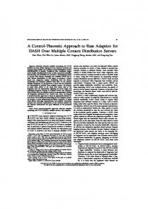
2. EFM and bandwidth allocation EFM is intended to provide Ethernet subscriber services to businesses and residences. “First Mile” refers to the first link between subscribers and their Internet service provider. By making Ethernet the first link, EFM is envisioned to provide high bandwidth services at low cost to the end users. Companies such as Yipes [8] and Cogent Communications [1] are already offering IP or Ethernet services to businesses. A “fat pipe” (e.g., a 100Mbps Ethernet on a fiber) is brought to the business (or residential neighborhood) and bandwidth can be allocated (i.e., sold) in increments. In order to achieve bandwidth allocation at high utilization levels, a mechanism for controlling and policing source bandwidth is needed. For this requirement, we propose that a new RATE flow control mechanism be added to IEEE 802.3 standard. Figure 1 shows an example EFM application where two server farms feed a (future) 10-Gbps Ethernet link. Each server farm is allocated a fixed amount of bandwidth (in this figure, server farm 1 and 2 are allocated 1-Gbps and 100-Mbps respectively). The multiplexer is a powered device that operates like a switch, except there is only one output port destination for outbound traffic (inbound traffic is switched to the correct destination). Both server farms and the multiplexer are within the premises. The fat pipe is the EFM service.
This material is based upon work supported by the National Science Foundation under Grant No. 9875177.
credit arrivals
Premises
overflow
Server farm #1
Credit bucket
1-Gbps allocation
bucket_size total_credit
Multiplexer Fat pipe Server farm #2 100-Mbps allocation
frame arrivals
frame departures
Buffer (transmission not permitted)
Buffer (transmission permitted) Credit matching next_frame_size
Figure 1. Example application of EFM
3. Proposed RATE flow control We propose a leaky bucket mechanism that can be used at a source node and/or within a multiplexer or switch. The leaky bucket mechanism can be used to control and police the frame transmission rate of a source. In order to maintain accurate bandwidth, a credit bucket has to be incremented at various clock rates for different transmission rate. For accurate bandwidth allocation in single and tens of Mbps increments, implementing a timer that can accurately maintain different clock cycles required for all possible transmission rates is not feasible. We propose a byte-based leaky bucket policy to resolve the issue of clock inaccuracy. Instead of incrementing the leaky bucket by one byte unit with variable clock rates, the proposed leaky bucket utilizes a feasible fixed clock rate and a variable incremental byte per clock cycle. Figure 2 shows a leaky bucket mechanism. Frames of length, frame_size, arrive into a buffer and are given permission to be transmitted only when frame_size bytes of credit exist in the credit bucket. The permitted frame is immediately transmitted if all of the previously permitted frames are already transmitted. As a frame receives permission, frame_size bytes of credit are removed from the credit bucket. Credits, of credit_size corresponding to an allocated transmission rate, are put into the bucket every clock_tick seconds. The bucket is fixed size; credits that arrive when the bucket is full are lost. We choose a clock cycle value such that bandwidth can be allocated in 10-Mbps increments from a 1-Gbps Ethernet. By selecting a clock cycle equivalent to the time required to transmit 100 bytes of data, 1%, or 10Mbps, increments are possible. For example, 12% bandwidth (or 120-Mbps) of 1-Gbps can be maintained by incrementing the credit bucket by 12 bytes per clock cycle given an 800 nanosecond clock cycle. For finer granularity, a clock rate of 8 microseconds may be used to allocate 1-Mbps increments of a 1-Gbps link or 10Mbps increments of a 10-Gbps link.
clock_tick: credit_size: total_credit: bucket_size: frame_size: next_frame_size:
Clock speed Size of credit Size of total credit resides in bucket Size of leaky bucket Size of frame being compared Size of the frame at the head of non-permitted frame queue
while(TRUE) { wait(clock_tick) total_credit = total_credit + credit_size if (total_credit > bucket_size) total_credit = bucket_size frame_size = next_frame_size while((total_credit >= frame_size) && (non-permitted frame exists)) { give a frame transmission permit total_credit = total_credit – frame_size frame_size = next_frame_size } }
Figure 2. Leaky bucket mechanism
3.1 Design of RATE control EFM subscribers may consist of a group of provider services such as web server farms, residential households, commercial backup servers, or a mixture. For a web server farm, outgoing bandwidth would typically exceed incoming bandwidth. Hence, outgoing bandwidth allocation is more crucial than incoming bandwidth allocation. On the other hand, households and data backup servers may be more interested in guaranteed incoming bandwidth. Thus, bandwidth allocation in both directions of a link is needed. In this paper we focus on the effects of outgoing bandwidth allocation (e.g., in the case of selling bandwidth to server farms). RATE flow control can be added to both PAUSE compatible and PAUSE non-compatible links as shown in Figure 3. Case 1 shows a condition where neither RATE nor PAUSE is in effect. This configuration applies when the Ethernet adaptor at the source and the multiplexer
both do not support IEEE 802.3x PAUSE flow control. Replacing the Ethernet adaptor at the source of case 1 with a RATE supporting adapter results in case 2. Replacing the multiplexer of case 1 with a RATE supporting multiplexer results in case 3. By replacing both the source adapter and the multiplexer in case 1 with RATE supporting interfaces results in the case 4 configuration. Case 5 supports PAUSE only. For our case 6, the source adapter is PAUSE enabled and the multiplexer supports RATE.
3.2 Bounding bandwidth misallocation of RATE A leaky bucket with a single byte increment guarantees a correct bandwidth allocation at any given time instant since the bucket counter is incremented by one, and the bucket is “drained” as soon as the byte counter reaches the size of the frame at the head of the queue. In the case of using multiple bytes increments, the value of total_credit may exceed the frame_size being compared. Consequently, by the time the total_credit exceeds the frame_size being compared, the actual transmission rate has become lower than the allocated transmission rate. For a proper bandwidth allocation, bucket_size needs to be carefully selected. It should be small enough to minimize the maximum burst allowed. However, a link that has been idle must allow a single arriving frame to be immediately transmitted. The credit bucket needs to be large enough so that under allocation of bandwidth can be prevented. The following example shows how under allocation of bandwidth can occur if bucket_size is selected incorrectly. Assume a leaky bucket with a bucket_size of 1500 bytes, a current total_credit of 1499, and a credit_size of 100 bytes. The next credit increment results in total_credit exceeding the bucket_size, thus total_credit is truncated to 1500. The variable total_credit loses 99-bytes of “bandwidth” that could have been used for the next frame transmission if we had set a bucket_size greater than 1500 bytes. The byte based leaky bucket can guarantee accurate bandwidth allocation if the correct bucket_size value is used. We derive the minimum bucket_size required to guarantee the accurate bandwidth allocation as follows. If (total_credit + credit_size) > bucket_size then total_credit = bucket_size. Hence, credits wasted = (total_credit + credit_size) – bucket_size. The value of total_credits is the maximum value when the largest frame waits its matching with a total_credit with a difference of 1 byte. Thus, the maximum total_credit = max(frame_size) – 1. To avoid under allocation, bucket_size > 1500 – 1 + 100 = 1599. In our case, the maximum credit_size is 100 when 100% of a 1-Gbps link is allocated. For this reason, a 1600 byte bucket_size is sufficient. The misallocation period can be bounded for any bucket_size greater than the maximum frame_size. For a
Source
M U X
Source Case 1: No flow control Source RATE
M U X
Source RATE
Case 2: RATE in source, but not in multiplexer Source
RATE
Source
RATE
M U X
Case 3: RATE in multiplexer, but not in source Source RATE
RATE
Source RATE
RATE
M U X
Case 4: RATE in both multiplexer and source Source PAUSE
M U X
Source PAUSE Case 5: PAUSE only Source PAUSE
RATE
Source PAUSE
RATE
M U X
Case 6: PAUSE in source and RATE in multiplexer
Figure 3. Possible control cases
simple case, we assume that all frames are fixed size. The number of clock cycles required to satisfy a requested rate, C, for a series of frames with size, frame_size and credit_size bytes per clock cycle is, C=
lcm ( frame _ size, credit_siz e ) , credit _ size
(1)
where lcm(frame_size, credit_size) is the least common multiple. The minimum number of clock cycles required to satisfy a requested rate is 1 and it occurs when credit_size is divisible by frame_size. The maximum number of clock cycles required to satisfy a requested rate is equivalent to frame_size and it occurs when lcm(frame_size, credit_size) is a product of frame_size and credit_size. For example, a fixed frame size of 1500 bytes, a 12% bandwidth allocation on a 1-Gbps Ethernet link, and an 800 nanosecond clock, the minimum number of clock cycles required is, credit_size = 100 bytes x 0.12 = 12 bytes, C(1500, 12) = 125 clock cycles. At 800 nanoseconds per clock cycle, we get 100 microseconds as the total time to exactly achieve the allocated bandwidth.
50
15
Mean response time (milisec)
Mean response time (milisec)
Case (1) Case (5) 10
5 Cases (2), (3), (4), and (6)
40
Cases (2), (3), (4), and (6)
30 20 Cases (1) and (5) 10 0
0 400
500
600 700 800 Offered load per port (Mbps)
900
1000
Figure 4. Results for the flow isolation experiment
4. Simulation evaluation of RATE control We evaluate the effectiveness of RATE in the context of providing allocated bandwidth for a server farm. Using CSIM18 [6], we model a 16 port multiplexer with full-duplex links that are not controlled, PAUSE controlled, and/or are RATE controlled. The traffic models used are a Poisson source or a bursty source with exponentially distributed on and off periods For the bursty source, the frame arrival rate is set to 100% utilization during on periods of mean duration of 100 microseconds while the off period duration is varied to achieve a target offered load. Frame lengths are pulled from the empirical IEEE workstation mix frame distribution used in the original performance evaluation of 1-Gbps Ethernet [3].
4.1. Description of experiments For all experiments, we use a 16-port frame multiplexer with 1-Gbps input links and a 10-Gbps output link (the external “fat pipe”). This allows for overallocation of bandwidth and thus interference between sources. Each input port and source has 1-Mbyte of buffering with low and high thresholds set at 100 and 900-Kbytes (for PAUSE flow control, when enabled). We model a link length of 1 mile. We measure frame delay and loss in all experiments. Frame delay is the sum of queueing at the sender, propagation delay on the link, queuing time at the input buffer, and service time at multiplexer. We evaluated the following six cases: 1. No control 2. RATE control in the sources only 3. RATE policing in the multiplexer only 4. RATE control in the sources and RATE policing in the multiplexer 5. PAUSE control by threshold in the multiplexer. 6. PAUSE control by threshold and RATE policing in the multiplexer
0
1
2
3
4
5 Port #
6
7
8
9
10
Figure 5. Results for the fairness experiment Flow isolation experiment: To evaluate flow isolation, we “sell” 1-Gbps of bandwidth to a link connected to port 0 of the 16-port multiplexer and 100Mbps to the remaining 15 input links for a total allocation of 2.5-Gbps. Thus, ports 1 through 15 are misbehaving when they offer in excess of 100-Mbps. Each source generates Poisson arrivals with an offered load from 100Mbps to 1-Gbps. We measure the frame delay and loss for the 1-Gbps port 0 link. Fairness experiment: To evaluate fairness, we “sell” 1 to 9 units of 100-Mbps of bandwidth to links connected to ports 1 to 9 of the 16-port multiplexer, respectively. That is, port 1 is allocated 100-Mbps, port 2 is allocated 200-Mbps, and so on. Port 0 and 10 have no bandwidth and 1-Gbps is allocated to the remaining 5 input links (i.e., ports 11 to 15) for a total allocation of 9.5-Gbps. Bursty traffic sources are used with an offered load equivalent to the bandwidth allocated. We measure the frame delay for ports 1 through 9.
4.2. Experiment results Figure 4 shows the flow isolation results. The frame delays of the no flow control and PAUSE cases significantly increase as the total offered load increases. On the other hand, the frame delay of all RATE cases remain below 1 millisecond for offered load less than 1Gbps per port. This shows that RATE isolates individual traffic flows. As expected, frame loss is observed only for the no flow control case. Figure 5 shows the fairness results. The mean frame delays for the 100 to 900-Mbps links all have similar values for no flow control and PAUSE cases while they differ for the RATE controlled cases. The link with the lowest bandwidth allocated has the largest mean delay while the highest bandwidth allocated has the smallest mean delay. This is as expected since queueing delay for a given utilization is inversely proportional to service rate. Each leaky bucket thus creates a “virtual link”.
5. Summary and Future Work
References
Future Ethernet in the First Mile (EFM) technology will need bandwidth allocation mechanisms to provide subscriber services. We have proposed that a new RATE flow control mechanism be added to the IEEE 802.3 Ethernet standard. Our proposal is a byte-based leaky bucket that uses a fixed clock rate and variable credit allocations. Though a byte-based leaky bucket introduces bandwidth misallocation for a period of time, this period can be bounded. We show how to bound this time and what size the token bucket needs to be. Simulation results show that the proposed RATE mechanism can both isolate flows and is fair. Future work will address performance evaluation of the mechanisms using traffic flows from real applications.
[1] Cogent Communications, 2001. URL: http://www.cogentco.com/ [2] EFM working group, Home Page for EFM working group, 2001. URL: http://www.manta.ieee.org/groups/802/3/efm/ [3] H. Frazier, Jr., “Scaling CSMA/CD to 1000-Mbps: An Update, “IEEE P802.3z Gigabit Task Force Meeting, July 9, 1996. [4] IEEE 802.3x, Specification for 802.3 Full Duplex Operation, IEEE Standard 802.3, 1997 Edition. [5] N. Noureddine, F. Tobagi “Selective Back-Pressure in Switched Ethernet LANs,” Proceedings of IEEE GLOBECOM, pp. 1256 -1263, 1999. [6] H. Schwetman, “CSIM18 - The Simulation Engine,” Proceedings of the 1996 Winter Simulation Conference, pp. 517 - 521, December 1996. . [7] J. Wechta, M. Fricker, and F. Halsall, “Hop-by-Hop Flow Control as a Method to Improve QoS in 802.3 LANs,” Proccedings of the Seventh International Workshop on Quality of Service, pp.239-247, May. 1999. [8] Yipes, 2001. URL: http://www.yipes.com/
Acknowledgments We thank the anonymous reviewers for their many helpful comments that have improved this work.
Appendix – RATE control specification This appendix specifies the RATE control mechanism in an exactly similar format as used in the IEEE 802.3 standard. In particular, this section is adapted from ANNEX 31A and ANNEX 31B of the IEEE 802.3 Specification for 802.3 Full Duplex Operation on IEEE standards 802.3.
RATE description The RATE operation is used to control frame transmission rate while its operation is enabled. A MAC Control client wishing to update the rate of the data frame transmission first generates a MA_CONTROL permit request specifying: a) The globally-assigned 48 bit multicast address 01-80-C2-00-00-01 b) The RATE opcode 00-02, c) A request_operand indicating the transmission rate of data frames. The RATE operation cannot be used to control transmission of MAC Control frames. RATE frames shall only be sent by DTEs configured to the full-duplex mode of operation. The globally-assigned 48 bit multicast address 01-80-C2-00-00-01, reserved for use in MAC Control PAUSE frames for inhibiting transmission of data frames from a DTE in a full-duplex mode IEEE 802.3 LAN, is used in MAC Control RATE frames. IEEE 802.1D-conformant bridges will not forward frames sent to this multicast destination address, regardless of the state of the bridge’s ports, or whether or not the bridge implements the MAC Control sublayer. To allow generic full-duplex flow control, stations implementing the RATE operation shall instruct the MAC (e.g., through layer management) to enable reception of frames with destination address equal to this multicast address.
NOTE-By definition, an IEEE 802.3 LAN operation in full-duplex mode comprises exactly two stations, thus there is no ambiguity regarding the destination DTE’s identity. The use of a well-known multicast address relieves the MAC Control sublayer and its client from having to know, and maintain knowledge of the individual 48 bit address of the other DTE in a full-duplex environment
Parameter semantics The RATE opcode takes the following request_operand from MAC Control RATE frame (see Figure 1a). rate_unit A 2 octet, unsigned integer containing the size of credit to be incremented by Check_byte_credit function. The field is transmitted most-significant octet first, and least-significant octet second. The range of possible rate_unit is 0 to 1000 as well as 65535 for disabling RATE control.
Detailed specification of RATE operation Transmit operation Upon receipt of a MA_CONTROL.request primitive containing RATE opcode from a MAC Control client, the MAC Control sublayer calls the MAC sublayer TransmitFrame function with the following parameters: a)
The destinationParam is set equal to the destination_address parameter of the MA_DATA.request primitive. This is currently restricted to the value specified in 31B.1.
b) The sourceParam is set equal to the 48 bit individual address of the station. c)
The lengthOrTypeParam is set to the reserved 802.3_MAC_Control value specified in 31.4.1.3.
d) The dataParam is set equal to the concatenation of the RATE opcode encoding, rate_unit request_operand specified in the MA_CONTROL.request primitive, and a field containing zeroes of the length specified in 31.4.1.6. Upon receipt of a MA_CONTROL.request from the MAC Control client through the MA_DATA.request primitive, if the transmission of data frames has not been controlled due to reception of a valid MAC Control frame specifying the RATE operation, the MAC Control sublayer calls the MAC sublayer TransmitFrame function with the following parameters: a)
The destinationParam is set equal to the destination_address parameter of the MA_CONTROL.request primitive.
b) The source Param is set equal to the 48 bit individual address of the station. c)
The lengthOrTypeParam and dataParam are set from the m_sdu field of the MA_DATA.request primitive.
Transmit state diagram for RATE operation It is not required that an implementation be able to transmit RATE frames. MAC Control sublayer entities that transmit RATE frames shall implement the Transmit State machine specified in this subclause. Constants rate_command The 2 octet encoding of the RATE command (00-02). reserved_multicast_address The 48 bit address (01-80-C2-00-00-01). 802.3_MAC_Control The 16 bit type field assignment for 802.3 MAC Control (88-08). phy_Address A 48 bit value, equal to the unicast address of the station implementing the MAC Control sublayer. clock_tick A clock speed used by Check_credit_byte function (800ns). bucket_size An integer indicating the size of leaky bucket used in Check_credit_byte function.
Variables TransmitEnabled A boolean set by Network Management to indicate that the station is permitted to transmit on the network. Value: true; Transmitter is enabled by management. false; Transmitter is disabled by management transmission_in_progress A boolean used to indicate to the Receive State Machine that a TransmitFrame function call is pending. Value: true; Transmission is in progress false; Transmission is not in progress xmit_count A integer counter used to maintain the total number of frames given a permission to be transmitted. credit_size An integer indicating the credit size to be incremented per clock_tick by Check_byte_credit function The value of rate_unit is assigned to credit_size upon receipt of MAC Control RATE frame (100 and 1000 for 100% transmission rate on 1 and 10-Gbps link, respectively). total_credit_size A counter indicating the size, in byte, to be compared with frame_size in Check_byte_credit function. frame_size An integer indicating the size, in byte, of frame being compared with total_credit_size in Check_byte_credit function. next_frame_size An integer indicating the size, in byte, of next frame being compared with total_credit_size in Check_byte_credit function. rate_control A boolean set by the MAC Control RATE Operation Receive State Machine to indicate RATE opcode. Value: true; the rate control is enabled false; the rate control is disabled Functions TransmitFrame The MAC Sublayer primitive called to transmit a frame with the specified parameters. Check_byte_credit A function that compares the size of total_credit_size and frame_size, and increment xmit_count if the value of total_credit_size is greater or equivalent to that of frame_size. The function is described as follow. Check_byte_credit() While (true) { Wait (clock_tick) total_credit_size = total_credit_size + credit_size If (total_credit_size > bucket_size) total_credit_size = While ((total_credit_size >= frame_size)&& frame exists) { total_credit_size = total_credit_size – frame_size frame_size = next_frame_size xmit_count = xmit_count + 1 } }
bucket_size
Messages MA_CONTROL.request The service primitive used by a client to request a MAC Control sublayer function with the specified request_operands.
MA_DATA.request The service primitive used by a client to request a MAC DATA transmission with the specified parameters.
Transmit state diagram for RATE operation Figure 2a depicts the Transmit State Diagram for a MAC Control sublayer entity implementing the RATE operation. Octets
8 Preamble
6 DA
6
2
2
SA Type/Length
01-80-c2-00-00-01
2
42
4
MAC Control Opcode rate_unit Reserved (0) FCS
88-08
00 - 02
Ext
*00-00 ~ FF-FF *00-00 ~ 03-E8: 0 ~1000 credit 03-E9 ~ FF-FE : Reserved FF-FF: Termination of RATE control
Figure 1a. MAC Control RATE Frame BEGIN
INITIALIZE TX permit_count = 0 transmision_in_progress = false
transmitEnabled = false HALT TX
transmitEnabled = true
transmision_in_progress = false
RATE CONTROL transmision_in_progress = false
MA_CONTROL.request (reserved_multicast_address, rate_command, credit_size) * permit_count = 0
rate_control = false || permit_count > 0
TRANSMIT READY
MA_CONTROL.request (reserved_multicast_address, rate_command, credit_size) * permit_count > 0
SEND CONTROL FRAME transmission_in_progress = true TransmitFrame(reserved_multicast_address, phys_Address) UCT
MA_DATA.request (destination_address, m_sdu, service_class) * ! MA_CONTROL.request (reserved_multicast_address, rate_command, credit_size) * transmission_in_progress = false * permit_count > 0 SEND DATA FRAME transmission_in_progress = true TransmitFrame(destination_address, m_sdu) permit_count = permit_count - 1 UCT
Figure 2a. RATE operation transmit state diagram