By transforming the data into the Doppler frequency domain a complete target de- ... the complex raw SAR data from the two (co-registered) channels, instead of ...
Raw Data based Two-Aperture SAR Ground Moving Target Indication Christoph H. Gierull and Ishuwa C. Sikaneta Defence R&D Canada Ottawa, 3701 Carling Ave, Ottawa, ON, Canada, K1A 0Z4 detecting the displaced, still focused, slow-moving control target [3].
8000
8200
8400
8600
Slant Range [m]
I. Introduction
9000
9200
9400
9600
9800
1000
2000
3000
4000 Azimuth bins
5000
6000
7000
8000
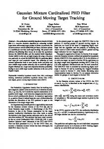
Fig. 1. Time-range image of two-channel SAR raw data after DPCA clutter cancellation.
In contrast, there is no bias against fast-moving objects in the received (uncompressed) data. This paper focuses on the feasibility, i.e., the theoretical background as well as a practical execution of raw data based techniques, see also [4], [5], [6]. The extension and enhancement of such techniques to along-track arrays with more than two antennas leads to space-time adaptive filtering (STAP) [1]. For a two-channel system it can be shown that DPCA is quasi-identical to the Signal-to-Clutter plus Noise (SCNR)optimum STAP-solution [7]. A statistical performance analysis in terms of the resulting receiver operator characteristics for ATI and DPCA has also been presented there.
Range bins
In many civilian and military applications of airborne and spaceborne SAR imaging, it is highly desirable to simultaneously monitor ground traffic. The measurement of object motion using SAR requires two operations. Firstly, detection in the SAR data and, secondly, parameter estimation such as of location, speed and trajectory. Target detection and estimation can either be performed incoherently with a single SAR sensor, or coherently, with much higher fidelity, with two or more apertures [1]. One possible method that is based on multiple phase centers is, for instance, SAR-ATI where two separate channels observe the same scene at different times. For stationary terrain the two channel signals are identical and can be canceled out by computing the phase difference (i.e., the interferogram), leaving only the moving targets in the differential data. Using the magnitude of the difference of the complex raw SAR data from the two (co-registered) channels, instead of the phase difference, is commonly referred to as the Displaced Phase Center Antenna (DPCA) technique. There are no restrictions on the PRF when the co-registration of the two channels is done digitally, in contrast to the classical DPCA with ‘physical’ co-registration (PRF is adjusted according to the platform velocity). Since SAR processing was originally developed to image the stationary world, the required information about a moving target in the SAR image is inevitably corrupted (smeared and de-focused) in proportion to its target velocity. Indeed, signals of fast-moving objects, with corresponding Doppler frequencies outside of the clutter bandwidth, are so mismatched to the processor filter that they are not imaged at all. Since these movers are buried in the clutter, conventional image-based techniques, such as ATI or DPCA, cannot detect them. Fig. 6 shows a focussed SAR image covering heterogeneous terrain in which it is known that there are fastmoving targets (on the highway, top-part) and a controlled slow-moving target (bottom left). The data were acquired during an experiment conducted at Canadian Forces Base Petawawa on July 14, 1999 with the Environment Canada CV 580 C-band SAR configured in its ATI mode [2]. ATI fails to detect the fast-moving targets but is capable of
8800
50
50
100
100
150
150
200
200
Range bins
Abstract— This paper investigates the capability of classical two-channel SAR ground moving target indication (GMTI) techniques, such as Displaced Phase Center Antenna (DPCA) or Along-Track Interferometry (ATI) when implemented on azimuth-uncompressed SAR data, rather than the processed SAR image. By transforming the data into the Doppler frequency domain a complete target detection and parameter estimation scheme is proposed. In contrast to the conventional image based algorithms, the proposed techniques are able to detect even fast movers. The GMTI feasibility is demonstrated with measured airborne data.
250
250
300
300
350
350
400
400
450
450
500
500 −200 0 200 Doppler Frequency [Hz]
−200 0 200 Doppler Frequency [Hz]
Fig. 2. Doppler-range image of two-channel SAR data before (left) and after DPCA clutter cancellation (right).
0-7803-7930-6/$17.00 (C) 2003 Canadian Crown Copyright
Interferometric Phase
II. SAR-GMTI in Raw Data Domain
Interferometric Magnitude 10 3
While for the investigation of conventional ATI and DPCA it is sufficient to look at the problem in a ‘static’ way, such as using two processed SAR images, methods working on the raw data require consideration of the time history of the received clutter and moving target echoes. In the following only stripmap SAR is considered, i.e., a fixed antenna pointing broadside and the received pulses are assumed to be already range-compressed. Let x(t, ξ) be the received echo consisting of a moving target signal s(t, ξ) superimposed upon the stationary clutter and the unavoidable thermal receiver noise. The parameters describing the moving target, such as velocity in along-track direction va , velocity in across-track or range direction vr and its location x0 at time t = 0 are combined in the vector ξ = [va , vr , x0 ]T . In the following, the Fourier-transform of the signal will be denoted as X(ω, ξ) = F{x(t, ξ)}. It is advantageous to have a closer look at the model for the received target signal at the ith channel: si (t, ξ) = Di (u(t, ξ)) exp(j2βRi (t, ξ)),
(1)
where Ri (t) denotes the slant range distance and ui (t) the direction history (directional cosine) from the ith antenna to the moving target on the ground. Di (u) describes the two-way antenna pattern of the ith channel. In the far-field assumption, ui (t) ≡ u1 (t) and the distances can be written as Ri (t) = R(t) + u1 (t)d, where d is the spacing between the receivers and R(t) is the slant range distance from the reference channel to the scatterer. The two-dimensional signal vector becomes � � D1 (u(t, ξ)) j2βR(t,ξ) s(t, ξ) = e D2 (u(t, ξ))ejβu(t,ξ)d = ej2βR(t,ξ) a(u(t, ξ)).
(2)
In array processing terminology the vector a(u) is called the steering or direction-of-arrival (DOA) vector. Since the chirp has a large time-bandwidth product, the method of stationary phase can be utilised and the Fourier-transform of (2) can be analytically computed to give S(ω, ξ) ∼ = γ(ω)a(u(ω, ξ)) [8]. This states that the target signal in the Doppler domain is a multiple γ of the DOA-vector in (Doppler frequency dependent) direction (va − vp )ω vr +� 2β[(va − vp )2 + vr2 ] (va − vp )2 + vr2 � ω · 1− � . (3) 2β (va − vp )2 + vr2
u(ω, ξ) = −
For non-moving objects this dependency tends to a straight line u(ω) = −ω/(2βvp ). For space-borne systems with platform velocity vp >> va , (3) can be simplified to u(ω, ξ) ∼ = −ω/(2βvp ) + vr /vp . A. Detection Inserting the linear Doppler dependency of the direction u for the stationary scatterer into the phase (2) yields φ(ω) = βu(ω)d = d/(2vp ) ω,
(4)
where the slope describes the time delay between the azimuth signals at each channel caused by the phase center separation d/2. Removing this phase ramp, therefore
50
50
9
100
100
8
150
7
200
200
6
250
250
5
2.5
150 2
1.5 300
300 1
350
400
4
350
3
400
2
0.5 450
450
500
500 −200 0 200 Doppler Frequency [Hz]
1
−200 0 200 Doppler Frequency [Hz]
Fig. 3. Interferometric phase (left) and interferometric magnitude (right) of the SAR raw data in Doppler-range domain.
means proper co-registration of the two channels. Moving targets deviate from this straight line in slope and offset depending on the parameter vector ξ. Hence, after subtraction of the two co-registered channels (either the complex pixels (DPCA) or the phase (ATI)), the clutter will be canceled and the targets will pop up. It is important to note, that any subtractive method relies on accurately calibrated channels. In this work, Ender’s digital channel balancing technique has been successfully applied [8]. Fig. 1 illustrates detections on the raw data corresponding to the SAR image in Fig. 6. Several vehicles moving on the highway (top) and a slowly moving control vehicle (bottom) are now visible. Since there is no compression gain in azimuth, each target signal spreads out over a distance related to the antenna beamwidth and its velocities. DPCA and ATI also work on raw data in the Doppler frequency domain, as shown in Fig. 2. On the left side, a clutter bandwidth of about 300 Hz is noticeable and after clutter suppression (right) the different movers show up at positions according to their radial velocity. A degree of compression gain can be achieved by dividing the entire slow-time region into smaller segments of equal duration which are individually transformed into the Doppler domain. The detection and parameter estimation is then done in the Doppler-range domain separately for each segment, for instance, by comparing the cluttersuppressed pixels with a pre-defined CFAR threshold. The duration of the time segments can be chosen as the maximum time stationary targets stay in one Doppler cell. B. Parameter Estimation The Doppler domain interferometric phase of a small non-overlapping time segment with 256 pixels is shown in Fig. 3 (left). One fast highway vehicle and the slower mover are recognizable, compressed into only a few Doppler cells. In the exo-clutter region the phase noise prevails because the antenna gain vanishes. However, using, for instance, the interferogram’s magnitude (right) allows detection of faster targets outside the clutter band; one vehicle is visible in the upper right. Having determined the Doppler frequency fˆt and the ˆ t at this stage, the only remaining slant-range position R unknown parameter is the azimuth location xt , or equivalently the target direction ut = xt /Rt . For a multi-channel
0-7803-7930-6/$17.00 (C) 2003 Canadian Crown Copyright
400 14 300 12 200
Doppler Frequency [Hz]
Range Line 140
10
8
6
4
100
0
−100
−200
2
−300
1000
2000
3000
4000
5000
6000
7000
−400
8000
0
5
10
15 20 Time segment
Azimuth Bins
Fig. 4. Magnitude of the co-registered channel difference (DPCA) for range line 140 (8430 m) superposed to the correlation result with a gaussian window.
25
30
35
Fig. 5. Instantaneous Doppler frequency estimates for nonoverlapping time segments. 8000
ω(t) = −
2β[(va − vp )2 + vr2 ] t + 2βvr , R
(5)
for vr and va . Alternatively, after extracting the target signal along the detected time-range trajectory in the raw data set (see Fig. 1), Maximum-Likelihood estimates of both velocity components can be obtained by varying vr and va in the matched filter until the compressed response yields a maximum [2]. Further, the interferometric phase φ = βdvr /(va − vp ) at the peak of the matched filter response represents an additional metric for the target velocity . In Fig. 6 the automatically detected targets are placed on the stationary SAR image and their estimated courses and speeds are stylized by direction and length of lines, respectively. One obvious false alarm at the top is observed. Here, the location estimation was based on the maximum DPCA energy for the individual non-overlapping time segments, therefore, possessing an error on the order of half the segment duration, i.e., �xt ∼ 128vp /P RF ∼ = 25 m. Allowing some segment overlap may reduce this error but also increases the computational load. III. Conclusions This paper presented an automated SAR-GMTI processing concept based on the range compressed, azimuth un-
8200
8400
8600
Slant Range [m]
SAR system with N > 2, Ender [8] has proposed an elegant method to estimate this direction. He used the measured array-manifold to yield high resolution azimuth spectra for DOA estimation. This approach cannot directly be applied to a two-channel system such as RADARSAT-2 because one degree-of-freedom is spent suppressing the clutter and the remaining one is not enough to retrieve the direction information. This problem can be overcome by exploiting full space-time samples, e.g. via PRI staggering, to estimate the required directions even after clutter suppression. However, since the DPCA output, shown in Fig. 1 is modulated by the azimuth antenna pattern, the ”center of mass” can be used as a rough estimate of xt , see Fig. 4, assuming a relatively smooth RCS aspect angle dependency. By calculating the slope and Doppler centroid of the instantaneous Doppler frequency estimates, shown in Fig. 5, one can solve the linear Doppler-time dependency
8800
9000
9200
9400
9600
9800
0
200
400
600
800 Azimuth [m]
1000
1200
1400
1600
Fig. 6. SAR image of CFB Petawawa with marked detections. The length of the lines relate to the magnitude of the velocity estimates, and their orientation to the estimated course.
compressed (raw) data. Using the received echo pulses before SAR processing avoids the information loss of fastmoving objects as occurring in conventional GMTI based on the compressed SAR image. The effectiveness of this approach has been demonstrated with measured two-channel airborne SAR data. References [1] J. H. G. Ender, “Space-time processing for multichannel synthetic aperture radar,” IEE Electr. and Comm. Engineering J., pp. 29– 38, Feb. 1999. [2] Livingstone, C., Sikaneta, I., Gierull, C.H., Chiu, S., Beaudoin, A., Campbell, J., Beaudoin, J., Gong, S. and T. Knight, “An airborne SAR experiment to support RADARSAT-2 GMTI,” Canadian J. Remote Sensing, vol. 28, no. 6, pp. 1–20, Dec. 2002. [3] C. H. Gierull, “Statistics of multilook SAR interferograms for CFAR detection of ground moving targets,” in Proc. of EUSAR, Cologne, Germany, 2002, pp. 625–628. [4] H. Sun, W. Su, H. Gu, G. Liu and J. Ni, “Performance analysis of several clutter cancellation techniques by multi-channel SAR,” in Proc. EUSAR Conf., Munich, Germany, 2000, pp. 549–552. [5] E. Yadin, “A performance evaluation model for a two port interferometer SAR-MTI,” in Proc. IEEE Nat. Radar Conf., 1996, pp. 261–266. [6] E. F. Stockburger and D. N. Held, “Interferometric moving ground target imaging,” in Proc. IEEE Int. Radar Conf., 1995, pp. 438–443. [7] C. H. Gierull and C. Livingstone, “SAR-GMTI concept for RADARSAT-2,” in The Applications of Space-Time Processing, R. Klemm, Ed. IEE Press, Stevenage, UK, 2003. [8] J.H.G. Ender, “The airborne experimental multi-channel SAR system AER-II,” in Proc. EUSAR’96 Conf., K¨ onigswinter, Germany, 1996, pp. 49–52.
0-7803-7930-6/$17.00 (C) 2003 Canadian Crown Copyright