PIERS Proceedings, Stockholm, Sweden, Aug. ... In Electromagnetics Research Symposium Proceedings, Stockholm, Sweden, Aug. .... 312, 1777â1780, 2006.
PIERS Proceedings, Stockholm, Sweden, Aug. 12–15, 2013
1792
Ray Tracing in an Arbitrary Cloak in Two Dimensions H. H. Sidhwa1 , R. P. Aiyar2 , and S. V. Kulkarni1 1
Department of Electrical Engineering, Indian Institute of Technology, Bombay, India 2 CRNTS, Indian Institute of Technology, Bombay, India
Abstract— Electromagnetic wave behaviour in an anisotropic medium with a two dimensional arbitrary geometry is studied. The aim is to trace the path of a ray in such a complex medium for the purpose of achieving cloaking (invisibility). A coordinate transformation is carried out for the formulation of an annular region at the centre of the structure whose topology is a scaled geometry of outer boundary of the structure. 1. INTRODUCTION
The idea of invisibility has intrigued and fascinated mankind for thousands of years. The motive is to bend the path of a ray around the body of interest so as to give an impression that the ray is travelling in a straight line uninterrupted by any obstacle. The idea of using coordinate transformation for altering the material characteristics, which would in turn cause a change in the formulation of Maxwell equations, was first espoused by Pendry et al. [1] and Leonhardt [2] in 2006. A process of ray tracing in transformed media for spherical and cylindrical cloaks using Cartesian tensors was carried out by Pendry et al. [3]. A generalized method for designing arbitrarily shaped cloaks using transformation of coordinates approach has been discussed by Li and Li [4]. A full wave simulation using a commercial software is carried out to verify the method. In this paper, an attempt has been made to carry out a ray tracing process for an arbitrary two dimensional cloak. The region to be cloaked is represented as an arbitrary closed curve in a two dimensional space. For the purpose of cloaking the region inside the domain is to be mapped to an annular region similar to the approach given by Li and Li [4]. A coordinate transformation is carried out for the formulation of an annular region at the centre of the structure with outer and inner boundaries having same shape. The formulation for the Hamiltonian is done as reported in [3]. Expressions for permittivity and permeability in the anisotropic medium in the transformed medium are calculated. For verification of the method, it is assumed that the arbitrary geometry is elliptical in nature. The Hamiltonian is formulated by including terms dependent on cylindrical polar coordinate, θ. 2. ANALYSIS OF TWO DIMENSIONAL ARBITRARY CLOAK
A point in space can be expressed by (r, θ, z) in cylindrical coordinates [4]. x = r cos θ
y = r sin θ
In a 2 dimensional geometry, let the shape of the outer contour be arbitrary in nature. Let r = R(θ) define the outer contour. We can define a normalised parameter as: p r x2 + y 2 ρ= = R(θ) R(θ) For a given path, ρ remains constant while the wave traverses path of 360◦ . The coordinates can now be expressed as x = ρR(θ) cos θ
y = ρR(θ) sin θ
(1)
For the process of cloaking, we define a transformation which compresses any point lying in the region 0 ≤ ρ ≤ 1 to τ ≤ ρ0 ≤ 1. The new region formed is an annular surface with coordinate system (ρ0 , θ0 , z 0 ). The relationship between the original and transformed coordinate systems can be expressed as: 0 < ρ < 1 ⇒ τ < ρ0 < 1
∴ ρ0 = τ + (1 − τ )ρ θ0 = θ
z0 = z
Progress In Electromagnetics Research Symposium Proceedings, Stockholm, Sweden, Aug. 12-15, 2013 1793
Outside the cloaked region lies free space for which corresponding characteristics can be used. The corresponding transformed Cartesian coordinates can now be expressed as [4]: x0 = r0 cos θ0 = ρ0 R(θ0 ) cos θ y 0 = r0 sin θ0 = ρ0 R(θ0 ) sin θ h i p x y x0 = τ R(tan−1 ) + (1 − τ ) x2 + y 2 p x x2 + y 2 h i p y y y 0 = τ R(tan−1 ) + (1 − τ ) x2 + y 2 p 2 x x + y2
(2) (3)
z0 = z
(6)
(4) (5)
Relative permittivity and permeability tensors can also be transformed as [6]: 0 0
0
²i j = |Λii |−1 Λi0 i Λj 0 j ²ij µ ²
0
i j0 0
x x0 0
0
0
0
(7)
0
=
|Λii |−1 Λi0 i Λj 0 j µij
=
|Λxi |−1 Λx0 i Λx0 j ²ij
0
(8) =
0
|Λxx |−1 Λx0 x Λx0 x ²xx
+
0
|Λxy |−1 Λx0 y Λx0 y ²yy
0
0
0
0
0
0
²x y = |Λxi |−1 Λx0 i Λy0 j ²ij = |Λxx |−1 Λx0 x Λy0 x ²xx + |Λxy |−1 Λx0 y Λy0 y ²yy ²y
y
x0 x0
= |Λyi |−1 Λy0 i Λy0 j ²ij = |Λyx |−1 Λy0 x Λy0 x ²xx + |Λyy |−1 Λy0 y Λy0 y ²yy
(9) (10) (11)
x0 x0
(12)
0 0
0 0
(13)
y0 y0
y0 y0
(14)
µ
=²
µx y = ²x y µ
=²
The final expressions for the permittivity in the transformed coordinate system can be seen in [4]. 3. CALCULATION OF HAMILTONIAN
Since there is no loss of energy while the wave propagates through the medium, the Hamiltonian (given by the following expression) can be found in order to trace the path of the wave in the cloaked medium [3]. 1 H = (1 − τ )(knk − |n|) 2 1 r0 − τ R |n| = |²| = (1 − τ )2 r0 0
0
0 0
(15) (16) 0 0
0 0
H = kx2 ²x x + 2kx ky ²x y + ky2 ²y y + kz2 ²z z − |²|
(17)
where n is the refractive index of the medium and k is the propagation vector. The path can be parametrised as [5]: dx ∂H = dς ∂k
dk ∂H =− dς ∂x
where ς is the parameterising varaible and x is the position vector. The Hamiltonian can be solved as per [5] as: ∂H 0 0 0 0 = 2kx ²x x + 2ky ²y y ∂kx ∂H 0 0 0 0 = 2kx ²x y + 2ky ²y y ∂ky ∂H 0 0 = 2kz ²z z ∂kz
(18) (19) (20)
PIERS Proceedings, Stockholm, Sweden, Aug. 12–15, 2013
1794 0
0
0 0
0 0
0 0
∂H ∂²x x ∂²x y ∂²y y ∂²z z ∂|²| = kx2 + 2kx ky + ky2 + kz2 − ∂x ∂x ∂x ∂x ∂x ∂x · ¸ ∂R ∂R A = (r0 − τ R)2 + τ 2 ( )2 cos2 θ − 2τ r0 sin θ cos θ + r02 sin2 θ ∂θ ∂θ 0 0 1 A ²x x = 0 0 r (r − τ R) · ¸ 0 0 ∂²x x 1−τ ∂R ρ0 − τ ∂A = sin θ 0 0 2A − ∂x r (r − τ R)2 ∂θ r0 − τ R ∂θ 0
0
0 0
0 0
0 0
(21) (22) (23) (24)
0 0
The expressions for ∂²x x /∂y, ∂²y y /∂x, ∂²y y /∂y, ∂²x y /∂x and ∂²x y /∂y can be calculated in a similar way for the calculation of ∂H/∂y. For the verification of the above algorithm, the outer contour is considered to have the shape of an ellipse with major axis a and minor axis b. R= p ∂R ∂θ ∂2R ∂θ2
ab
b2 cos2 θ + a2 sin2 θ ¡ ¢ sin θcosθ b2 − a2 ab =¡ ¢3/2 b2 cos2 θ + a2 sin2 θ µ ¶ ¡ 2 ¢ (b2 − a2 ) sin2 2θ cos 2θ 3 2 = b − a ab + (b2 cos2 θ + a2 sin2 θ)3/2 4 (b2 cos2 θ + a2 sin2 θ)5/2
(25) (26) (27)
On substituting for R and its derivatives in Eq. (17) for the Hamiltonian, and solving for position vector x and propagation vector k, the path of the ray inside the cloaked medium is traced. 4. RESULTS FOR AN ELLIPTICAL CLOAK
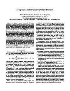
• The elliptical cloak in Fig. 1 shows that a medium with properties defined by Eq. (23) would exhibit cloaking for electromagnetic waves in geometric limit (the wavelength λ ¿ a and λ ¿ b in the case of ellipse). • Experimentally, these structures cannot be realized using naturally occurring materials. Metamaterials which have properties like Eq. (23), i.e., variable ²r , 0 < ²r < 1, etc., can realise such characteristics through split ring resonators or complementary split ring resonators.
Figure 1: Plot of elliptical cloak in an X-Y plane for
a b
= 2, τ = 0.5.
Progress In Electromagnetics Research Symposium Proceedings, Stockholm, Sweden, Aug. 12-15, 2013 1795 5. CONCLUSION
A generalized method for ray tracing of an arbitrarily shaped cloak in two dimensions by finding the corresponding Hamiltonian is illustrated. In the existing literature, formulations have been given for specific shaped cloaks and verified by ray tracing. Recently, algorithms have been proposed for arbitrarily shaped cloaks, but these algorithms have not been tested through ray tracing method. In this paper, one such algorithm has been used for realizing an arbitrarily shaped cloak. The method has been verified through ray tracing. Any arbitrary two dimensional closed curve can be parameterized by specifying ρ as a function of θ. The function ρ(θ) must be a single valued function of θ for the described algorithm to work efficiently. Thus, any curve satisfying the above characteristics can be cloaked and verified by the process of ray tracing. ACKNOWLEDGMENT
The authors would like to thank Prof. R. K. Shevgaonkar for his valuable suggestions throughout this work. The help given by Mr. Chinmay Rajhans towards the mathematical formulation is also appreciated. REFERENCES
1. Pendry, J. B. and D. Schurig, “Controlling electromagnetic fields,” Sciencemag., Vol. 312, 1779–1782, 2006. 2. Leonhardt, U., “Optical conformal mapping,” Science Express, Vol. 312, 1777–1780, 2006. 3. Shurig, D., J. B. Pendry, and D. R. Smith, “Calculation of material properties and ray tracing in transformation media,” Optics Express OSA, Vol. 14, No. 21, 9794–9804, 2006. 4. Li, C. and F. Li, “Two-dimensional electromagnetic cloaks with arbitrary geometries,” Optics Express OSA, Vol. 34, No. 10, 1064–1076, 2008. 5. Kravtsov, Y. A. and Y. I. Orlov, Geometric Optics of Inhomogeneous Media, Springer-Verlag, Berlin, 1990. 6. Post, E. J., Formal Structure of Electromagnetics, Wiley, New York, 1962.