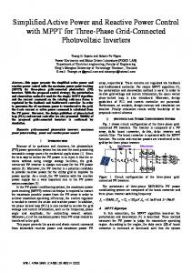
Reactive Power and Harmonic Currents Compensation in Traction Systems using Active Power Filter with DFT-based Current Reference Generator Tomáš Komrska, Jan Žák, Zdeněk Peroutka UNIVERSITY OF WEST BOHEMIA IN PILSEN Univerzitní 26 Plzeň, Czech Republic Tel.: +420/ 377 634 450. Fax: +420/ 377 634 002. E-Mail:
[email protected],
[email protected],
[email protected] URL: http://www.fel.zcu.cz
Acknowledgements This contribution was funded by the Czech Science Foundation under project GA ČR 102/09/1164.
Keywords «Active filter», «Real time processing», «Single phase system», «Power factor correction», «Power Quality», «Traction application»
Abstract This contribution deals with a shunt-type active power filter designed mainly for railway applications (50-Hz and 16.7-Hz electrification systems) which is able to compensate undesired harmonic currents as well as reactive power. Its control algorithm employs an optimized DFT-based fundamental current and voltage estimator generating an accurate control reference signal. The APF configuration, the current reference generator and the APF control algorithm are discussed in detail in this paper. Theoretical conclusions are verified beside simulations also by experiments on designed laboratory prototype of rated power of 5.75 kVA.
Introduction The motivation for this research has been a demand to design a shunt-type active power filter which would be able to operate on single-phase ac power systems of both 50Hz and 16.7Hz – the main attention is paid to traction power supply systems. This single-phase APF is designed for compensation of power grid voltage distortion caused by harmonic currents. Beside the harmonics suppression, the APF performs the compensation of the reactive power as well. It is possible to find many interesting papers in the literature where authors deal with APF and its control – e.g. [1] – [4]. Basically, proper operation of the investigated system is strongly dependent on an exact real-time estimation of the fundamental current/voltage component without any delay. Executing of the control algorithm according to a poor current reference naturally leads to unsatisfactory APF operation. We have explored many options of the reference generator implementation, e.g. using a weighted least squares estimation [5] or a predictive filter [6], [7]. Finally, we decided to employ an exact current reference generator based on the widely used discrete Fourier transform [8]. This method is expected to extract the 1st harmonics from the distorted voltage or current with exact information about its amplitude and phase angle. Since the APF control algorithm needs the information only about the fundamental component, the reference generator does not need perform computing of the whole DFT algorithm which considerably reduces the computational burden, and thus, this method is suitable for real-time applications. Moreover, we performed an optimization for DSP in assembly language which led to considerable reduction of computing time about 94% compared to the original algorithm in C language.
The whole system operation was simulated on a mathematical model first. Later on, we performed extensive experiments on a laboratory prototype intended for verification of the system operation and compensation ability. In this paper, we would like to present the structure of our APF laboratory prototype, the proposed control algorithm, simulation and experimental results. A special attention is paid to the accurate current reference generator based on the DFT and its estimation performance.
Shunt-type active power filter configuration In this section we will take a closer look at the system configuration which is shown in Fig. 1.
a)
b)
c)
Fig. 1: Shunt-type active power filter a) configuration with experimental nonlinear load; b) and c) proposed position of investigated APF in traction systems Traction vehicles employ adjustable speed drives with traction converters, and thus, they have the characteristics of a nonlinear load generating harmonic currents and corrupting the power factor. The explored active power filter is intended to be connected via transformer to a traction power system (Fig. 1b) for compensation of undesired harmonic currents or reactive power. Although, the APF could be placed also directly in a traction vehicle (Fig. 1c) to fulfill the same task as in previous case or it can be used for compensation of specific trolley wire current components generated by traction drive such as current components disturbing railway safety system. In our case, the configuration intended for illustrative experimental purposes contains a diode rectifier supplying RL or RC load (Fig. 1a). The rectifier representing a nonlinear load is supplied by the European power grid system
230 V/50 Hz. For investigation of the APF operation potential for traction power systems 15 kV/16.7 Hz, we can switch our programmable power source to 230 V/16.7 Hz. The active power filter (a single-phase IGBT-based inverter) is connected in parallel to the assembly representing a nonlinear load. Proper compensation of harmonics would not be possible without a constant DC link voltage and filter inductor Lf. Both parameters considerably affect compensation quality (current rise/fall time and hysteresis band). In principle, undesirable current components (trolley current distortion) are suppressed using the APF by injecting harmonic currents of opposite amplitude [9], which is a challenging task requiring exact real-time control. For proper APF operation it is necessary to employ a powerful control system executing a sophisticated control algorithm.
Control algorithm We employ a simple control algorithm containing a PS controller of the DC-link voltage and a current hysteresis controller. Consequently, the proposed control scheme (depicted in Fig. 2) is robust, and disposes by competitive dynamic behavior.
Fig. 2: Employed APF control scheme with hysteresis current controller and DFT-based reference generator The most demanding task of the APF control algorithm is the estimation of the fundamental current component which is used in following step for generation of APF current reference. The estimation quality considerably affects the APF ability to achieve a satisfactory performance. In principle, there are two main problems in the fundamental estimation. In case the estimated signal is not a pure sinusoid, consequently, the control algorithm operates according to a poor reference which corrupts the APF control strategy. Additionally, if the current reference generator introduces a propagation delay, then both the control algorithm and the distorted trolley current are not well synchronized which inevitably leads to compensation failure. Thus, it is necessary to employ an estimator which disposes by minimized THD of the estimated output signal to ensure high compensation quality and which does not introduces a harmful delay to the control process. In our case, we have employed a DFT-based current reference generator discussed in detail below. As we can see in Fig. 2, the current reference generator provides us with the fundamental harmonic amplitude Im and the phase angle φi of the distorted trolley current izd, and the phase angle of the trolley voltage φu. In order to remove the reactive current component and use only the active power current
component of the izd in control algorithm, the amplitude Im is multiplied by cos(φu-φi) in following step. The control algorithm contains a PS controller to ensure a constant value of the DC link voltage Uc. Its output is added to the amplitude of the active power current component, and next, the iref is computed using the sum and the cos(φu), in order to achieve cosφui → 1. The signal iref represents a desired trolley current which is synchronized with the trolley voltage. Once the iref is obtained, it is used in following step for computation of a desired APF current ifw by subtracting of the distorted trolley current izd from the iref. This step inevitably leads to notches generation in the compensated current. Assuming the distorted current izd is similar to a square-wave signal, and the iref is a pure sinusoid, by subtracting izd from iref we obtain the signal of APF desired current with very steep zero crossing (Fig. 2); it is a demanding task for the active power filter to track such a steep signal, and consequently, the resulting trolley current suffers by notches placed at zero crossings (as we can see in sections Simulation and Experimental results). Next, the difference between the instantaneous APF current if and its desired value ifw enters a classical hysteresis controller which generates firing pulses to IGBTs. By setting a hysteresis band ∆iz, we can adjust a switching frequency and so affect the trolley current quality.
DFT-based current reference generator Fundamental harmonic estimation methods based on the discrete Fourier transform have an advantage of pure sinusoid on the output. We can find some DFT modifications in literature such as sliding DFT [11] which is a computationally highly efficient algorithm, and thus, it is suitable for application in case of short sampling periods. Nevertheless, on the other hand, the sliding DFT is rather sensitive to computation accuracy. Introduction of an error into the phase angle computation for shifting the updated DFT output corrupts the estimation accuracy (amplitude and phase angle error) or it can even cause instability. Moreover, increasing of sample rate implies increasing demands on the phase angle computation accuracy leading to problems with conversion to a fixed-point arithmetic and implementation using digital signal processors. The classical DFT is a widely spread algorithm [8]. However, it disposes by a relatively high computational burden, and thus, it is not basically eligible for real-time applications. Nevertheless, for fundamental harmonic estimation purposes is it not necessary to compute all spectral components, but it is sufficient to extract only the first harmonic from the DFT algorithm (in our case 50 Hz or 16.7 Hz). Thus, we can considerably reduce the number of computing operations. Fig. 3 shows the employed DFT-based fundamental harmonic estimator.
Fig. 3: DFT-based fundamental signal component extraction Samples of the investigated signal (distorted voltage and current) are saved into the input buffer. The buffer is shifted every sampling period, the new sample x(n) is saved on the first position, and the last sample x(n-(N-1)) is cleared. Then, all samples are multiplied by e-jn2π/N corresponding to the first signal component (50 Hz or 16.7 Hz). Next, from the sum of complex multiplication we obtain a real and imaginary part. Finally, the amplitude and phase angle computation follow. Such an algorithm provides us with excellent accuracy as well as stability of the output signal. For the APF control algorithm is also advantageous the natural property of DFT; all transients have constant transient response duration (amplitude changes, phase angle step jumps, etc.). We have implemented this fundamental harmonic estimator in DSP TI TMS320F2812 (150 MHz) using the algorithm discussed above converted into a fixed-point arithmetic. In case of implementation using C language, the computation of 80-sample DFT (sampling period 250 μs) takes 98 μs which is still not very competitive period, and practically, such a implementation does not enable application of
sample rates higher than 6kHz. Beside the implementation in C language, we have performed the implementation of the DFT-based algorithm using assembly language as well. The instruction set of employed DSP offers several assembly language instructions optimizing arithmetical operations with sampled data. Due to repeated execution of an instruction which performs multiplication, accumulation and shift of the buffer simultaneously, we have achieved a reduction of the computation time to 5.64 μs (-94%) compared to the original algorithm in C language. Such an improvement of computation efficiency and time consumption makes from DFT-based current reference generator a competitive solution for APF control application. For this reason we could employ our optimized algorithm for estimation of both current amplitude as well as voltage phase angle.
Performance verification Simulation results In first step, the system operation has been simulated on mathematical model in Matlab/Plecs for both operation modes on 50-Hz and 16.7-Hz power systems as well as for both selected types of nonlinear loads (rectifier with RL and RC load). We have set the trolley voltage uz = 230 Vrms, the APF inductor Lf = 9 mH, the hysteresis band of the current controller ∆iz = 3.2 A, and the DC-link voltage command Ucw = 400 V. Fig. 4 shows selected simulation results where we can see the trolley voltage, the current drawn by the nonlinear load, the trolley current compensated by the APF, and the APF current. Steady state, 16.7-Hz power system
Steady state, 50-Hz power system
Trolley voltage
Nonlinear load current
Trolley current
APF current
Fig. 4: Simulation results: APF compensating the distortion caused by diode rectifier with RL load Steady state, 16.7-Hz power system
Steady state, 50-Hz power system
Trolley voltage
Nonlinear load current
Trolley current
APF current
Fig. 5: Simulation results: APF compensating the distortion caused by diode rectifier with RC load
According to theoretical assumptions, in case of RL load, the distorted current is similar to square wave, as shown in Fig. 4. Subtracting of this signal from the fundamental current component leads to a reference with very steep zero crossings (see section Control algorithm) causing undesired notches in the trolley current. On the other hand, this problem is minimized in case of the pulse current caused by RC load. Such a waveform does not contain steep edges and so it is not so demanding task for the APF to track the resulting desired APF current ifw.
Experimental results In addition to the extensive simulations described partly above, the system performance has been verified also by a real implementation. We have designed a straightforward laboratory prototype of single-phase active power filter (shown in Fig. 6).
Fig. 6: Designed laboratory prototype of single-phase active power filter The prototype consists of an intelligent power supply Agilent 6813B AC Power Source, the active power filter stage of rated power of 5.75 kVA based on Semikron IGBT switches SEMiX 202GB128Ds, an inductance Lf = 9 mH/25 A, and a single-phase diode rectifier supplying general RL or RC load (see Fig. 1 b) which has been used as a nonlinear load for disturbing the trolley current. In case of RC load, an additional inductor LRC = 6 mH has been connected in series to the nonlinear load (see Fig. 1 b) to avoid undesirable current oscillations and ensure a proper compensation performance. Measurements have been performed on the full power grid voltage 230 Vrms/50 Hz or 16.7 Hz; the DC-link (C = 4 mF) voltage command has been set to 400 V and the current hysteresis band ∆Iz to 3.2 A which implies the average switching frequency of 4 kHz. The control algorithms for both 16.7-Hz and 50-Hz power systems have been implemented using a 32-bit fixed-point digital signal processor TMS320F2812 (150 MHz) with a built-in 12-bit analogto-digital converter (implementation in C language, the DFT-based estimator in assembly language). The sampling period of the APF control has been set to 20 μs (DC-link voltage PS controller and current controller); 100 μs for the DFT-based current reference generator (50-Hz systems), and 300 μs (16.7-Hz systems). The performance of our DFT-based estimator extracting the fundamental signal component is shown in Fig. 7; the selected experimental results corresponding to simulation results are shown in Fig. 8-10.
Ch1
Ch4
Fig. 7: Experimental results: DFT-based estimator extracting a fundamental signal component Ch1: Power supply voltage/current signal Ch4: Estimated fundamental signal component Steady state, 16.7-Hz power system, P = 1.1 kW
Steady state, 50-Hz power system, P = 1.1 kW
Ch1
Ch2
Ch3 Ch4
Fig. 8: Experimental results: APF compensating the distortion caused by diode rectifier with RL load Ch1: Power supply voltage [100V/div.] Ch2: Distorted current drawn by nonlinear load [5A/div.] Ch3: Trolley current compensated by APF [5A/div.] Ch4: APF current [5A/div.]
Steady state, 16.7-Hz power system, P = 750 W
Steady state, 50-Hz power system, P = 687 W
Ch4
Ch3 Ch1 Ch2
Fig. 9: Experimental results: APF compensating the distortion caused by diode rectifier with RC load Ch1: Power supply voltage [100V/div.] Ch2: Distorted current drawn by nonlinear load [5A/div.] Ch3: Trolley current compensated by APF [5A/div.] Ch4: APF current [5A/div.] RL load connection, 16.7-Hz power system
RL load connection, 50-Hz power system
Ch1 Ch3 Ch2 Ch4
Fig. 10: Experimental results: APF compensating the distortion caused by diode rectifier with RL load Ch1: Power supply voltage [100V/div.] Ch2: Distorted current drawn by nonlinear load [5A/div.] Ch3: Trolley current compensated by APF [5A/div.] Ch4: APF current [5A/div.]
a) control angle α = 60˚
b) control angle α = 80˚
Ch1 Ch3
Ch2
Ch4
Fig. 11: Experimental results: APF compensating distortion and current phase shift caused by controlled thyristor full-bridge rectifier with RL load Ch1: Power supply voltage [250V/div.] Ch2: Distorted current drawn by nonlinear load [5A/div.] Ch3: Trolley current compensated by APF [5A/div.] Ch4: a) APF current [5A/div.], b) fundamental component of distorted load current [5A/div.] As we can see in Fig. 7, the DFT-based reference estimator is able to extract the 1st harmonic from different types of distorted signals with exact amplitude as well as phase angle estimation. Moreover, the absence of propagation delay (exact zero crossing) is crucial for proper harmonics compensation. The designed APF laboratory prototype disposes by satisfactory performance and it fully satisfied our intent—the verification of the proper function of the proposed reference current generator. As we can see in figures above showing selected experimental results, the implemented control algorithm disposes by sufficient robustness and enables compensation of different types of distorted currents. The proper APF operation is verified for both the current similar to square wave (rectifier with RL load) and the pulse current (rectifier with RC load). In both cases, the compensated trolley current is synchronized with the trolley voltage (cosφui → 1) and we have achieved an obvious quality improvement (sine wave). In addition, due to the employed hysteresis current controller, the control algorithm provides us with excellent dynamic behavior, as we can see in Fig. 10. The connection of the nonlinear load does not cause an improper transient response; its duration takes one period of trolley voltage. The reactive power compensation is depicted in Fig. 11. In this case, we have employed a controlled thyristor full-bridge supplying the RL load which causes the current phase shift. However, the trolley current keeps well the desired phase angle corresponding to the trolley voltage. It is possible to improve the trolley current quality. On the other hand, the reduction of ΔIz would lead to necessary increase of the average switching frequency which has been set to 4 kHz (for the given ΔIz = 3.2 A). Thus, if we liked to decrease the current ripple related to ΔIz, we have to increase either the active filter inductance (in our case over 9 mH), which is not eligible from the power circuit design point of view, or increase the average switching frequency.
Conclusion •
•
This paper deals with active power filter compensation of harmonic currents and reactive power for 16.7-Hz and 50-Hz railway power systems. The detailed discussions on compensating method, APF control algorithm, special current reference generator, and designed laboratory prototype are completed by simulations and experimental results. The crucial part of the control algorithm – the current reference generator for real-time extraction of fundamental current component is based on discrete Fourier transform which ensures the exact amplitude and phase angle real-time estimation without any delay.
•
•
•
•
The implementation of the DFT algorithm has been optimized using assembly language in order to reduce the computational burden. We have achieved a computation time reduction about 94% compared to original algorithm in C language (5.64 μs for sampling rate of 4 kHz). Thus, the proposed DFT-based estimation method is eligible for real-time applications such as APF control. Optimized implementation of the DFT-based estimator enables us to employ it for fundamental component estimation of both current and voltage. In consequence, the APF operation is possible under distorted trolley voltage, both the current reference and the voltage fundamental component are well synchronized (cosφui → 1). The proposed control algorithm has been implemented in fixed-point DSP Texas Instruments TMS320F2812. Its main advantages are simplicity (simple PS controller and current hysteresis controller) and robustness which enables us to operate with different types of distorted currents. Moreover, the hysteresis control of the APF current provides us with excellent dynamic behavior. Experiments performed on designed laboratory prototype of APF have verified proper operation of proposed control algorithm implemented in fixed-point arithmetic as well as simulation results in real-time environment.
References [1] A. Chandra, B. Singh, B. N. Singh, K. Al-Haddad, “An Improved Control Algorithm of Shunt Active Filter for Voltage Regulation, Harmonic Elimination, Power Factor Correction and Balancing of Nonlinear Loads", IEEE Trans. on Power Electronics, Vol.15, Nº3, pp.495-507, 2000. [2] Medina-Rios, A. Ramos-Carranza, H.A., “An Active Power Filter in Phase Coordinates for Harmonic Mitigation,” In:,IEEE Transactions on Power Delivery, July 2007, Volume: 22, Issue: 3, On page(s): 19911993. [3] H.-L. Jou, J.-Ch. Wu, Y.-J. Chang, Y.-T. Feng,” A novel active power filter for harmonic suppression,” In: IEEE transactions on power delivery, 2005, vol. 20 (2), no2, pp. 1507-1513. [4] K. P. Sozanski: Shunt Active Power Filter with Improved Dynamic Performance. Power Electronics and Motion Control Conference, 2008. EPE-PEMC 2008. 13th, Poznan, Poland. On page(s): 1995-1999. [5] Song H., Kwanghee N., Mutschler P.: Very Fast Phase Angle Estimation Algorithm for a Single Phase Systems having Sudden Phase Angle Jumps. IEEE IAS conference 2002, Pittsburg, USA, pp. 925-931. [6] S. Väliviita and S. J. Ovaska, “Delayless method to generate current reference for active filters,” IEEE Transactions on Industrial Electronics, vol. 45, no. 4, pp. 559–567, 1998. [7] B.-M. Han, B.-Y. Bae and S. J. Ovaska, “Reference signal generator for active power filters using improved adaptive predictive filter,” IEEE Transactions on Industrial Electronics, vol. 52, no. 2, 2005, pp. 576–584. [8] J. Bruce, “Discrete Fourier transforms, linear filters, and spectrum weighting”, IEEE Transactions on Audio and Electroacoustics, vol. 16, pp. 495-499, Dec 1968. [9] A. H. Samra and A. Teshome, “Current injection method to eliminate harmonics,” IEEE Industry Applications Magazine, vol. 1, no. 2, 1995, pp. 28–33. [10] Taufig, J: Power Electronics Technologies for Railway Vehicles. In: Power Conversion Conference – Nagoya, 2007. PCC’07 2-5 April 2007 Pages: 1388 – 1393, 10.1109/PCCON.2007.373146. [11] E. Jacobsen, R. Lyons, "The sliding DFT", Signal Processing Magazine, IEEE, Vol. 20, No. 2, March 2003.