IRANIAN JOURNAL OF ELECTRICAL AND COMPUTER ENGINEERING, VOL. 10, NO. 1, WINTER-SPRING 2011
49
Archive of SID
Reactive Power Control in Eight Bus System Using FC-TCR T. Vijayakumar and A. Nirmalkumar
Abstract—This paper deals with the simulation of eight bus system having fixed capacitor and thyristor controlled reactor. The system is modeled and simulated using MATLAB. The simulation results are presented. The power and control circuits are simulated. The current drawn by the TCR varies with the variation in the firing angle. The simulation results are compared with the theoretical results.
Z + L T
-
Lr R
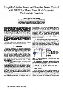
Fig. 1. Basic circuit of TCR.
Index Terms—Facts, TCR, MATLAB, FC, FFT, THD PWM, harmonics, Simulink, reactive power.
I
I. INTRODUCTION
control of Electric Power Systems, systems and procedures are used to compensate dynamically the detrimental effects of non-linear loads. The compensation process should be carried out without important alteration of source signal quality. Some benefits are expected using compensation reduction of losses in distribution lines, harmonic content minoration, and power factor improvement. The dynamic behavior of industrial loads requires the use of compensator that can be adapted to load changes. Unfortunately, the techniques frequently used for compensation are based on circuit controllers that alter the waveform of the signal subjected to control. Such is the case of the static compensator [1], [2], which must perform harmonic cancellation, reactive power compensation, power factor correction, and energy saving. Although the static compensator is commonly used and studied under sinusoidal voltage conditions, waveforms corresponding to the controlled current present high harmonic content. This paper focuses on the thyristor-controlled reactor [3]. as shown in Fig. 1. Compensation with TCR consists of controlling the current in the reactor L from a maximum (thyristor valve closed) to zero (thyristor valve open) by the method of firing delay angle control. The fixed capacitor (FC) and TCR constitute a basic VAR-generator arrangement (FCTCR). The constant capacitive VAR generation of C is opposed by the variable VAR absorption of the TCR. The circuit model of FC TCR system is shown in Fig. 2. Calculation of the firing angle can be made in the time domain or in the frequency domain, using different approaches. Assuming the supply voltage to be sinusoidal, calculation of the firing angle is obtained with minimum complexity. However, the increase in = / 2 to = , produces increasing distortion of the current in the TCR branch, and consequently that of line current. It increases N THE
Manuscript received November 5, 2009; revised January 17, 2011. T. Vijayakumar is with Department of Electrical and Electronics Engineering, KCE, Pollachi, India. (e-mail:
[email protected]). A. Nirmalkumar is with the Info Institute of Engineering and Technology Coimbatore, Tamilnadu, India. (e-mail:
[email protected]). Publisher Item Identifier S 1682-0053(11)1846
the rms value of the line current and the THD, and deteriorates the power factor. The literature [1] to [13] does not deal with the simulation of 8 bus system with FC-TCR system. An attempt is made in the present work to simulate 8 bus system with FC-TCR system using MATLAB® Simulink. II. STEP BY STEP ALGORITHM Step 1: Obtain the schematic structure of practical bus system (Sources, Transmission Lines, FACTS Devices and Load) using Simulink blockset. Step 2: Obtain the switching sequence of the FACTS Devices through Pulse Width Modulation scheme when operating between the active regions of the firing angles from 90 to 180 . Step 3: Run the simulation and study the impact of FCTCR with normal conditions. Step4: Obtain the voltage and reactive power quantities by connecting the above FACTS devices at different load nodes. Step 5: Demonstrate the impact of FC-TCR device when subjected to vulnerable condition such as non linear load fault conditions. III. SIMULATION RESULTS The components of FC-TCR are modeled in the simulink block set as shown in Fig. 2. FC-TCR is connected with a voltage source along with a transmission line. The triggering of FC-TCR is done by PWM technique between 90 and 180 . The firing angle of FC-TCR is set at 110 and the corresponding pulse waveform is illustrated in Fig. 3(a). The voltage and reactive power profile for the corresponding firing angle are illustrated in the Fig. 3(b).The bidirectional switch is implemented using 4 diodes and 1 thyristor. It is inferred that FC-TCR is regulating the reactive power and maintains the voltage profile within the tolerable limits. Since it is a power electronics device, the harmonic analysis is also demonstrated in the Fig. 3(c). The performance of real power due to FCR is also demonstrated in Fig. 3(d). The voltage, real and reactive power profiles for the FC-TCR firing angle 144 is also demonstrated from Figs. 3(e), 3(f).
1682-0053/11$20 © 2011 ACECR
www.SID.ir
50
IRANIAN JOURNAL OF ELECTRICAL AND COMPUTER ENGINEERING, VOL. 10, NO. 1, WINTER-SPRING 2011
Archive of SID
Fig. 2. Circuit model of FC-TCR..
(a)
(b)
(c)
(d)
(e)
(f)
Fig. 3. (a) Switching pulses of FC-TCR, (b) Voltage and reactive power with Alpha=110 , (c) FFT Analysis for the voltage, (d) Rea1 power with alpha=110 , (e) Voltage and reactive power with alpha=144 , (f) Rea1 power with Alpha=144 .
www.SID.ir
51
VIJAYAKUMAR AND NIRMALKUMAR: REACTIVE POWER CONTROL IN EIGHT BUS SYSTEM USING FC-TCR
Archive of SID
Fig. 7. FC-TCR circuit. Fig. 4. 8 Bus system.
Fig. 8. Voltage across load-1.
(a)
Fig. 9. Simulink model of eight bus system with non linear load.
(b) Fig. 5. (a) Voltage across load-1 and (b) voltage across load-2.
Fig. 10. Output voltage waveform across non linear load.
Fig. 6. 8 Bus system with FC-TCR.
From the illustrated demonstrations, it is inferred that the FC-TCR is capable of delivering the reactive power and regulates the voltage in the system. The above firing angles are selected because control range of lies between 90 and 180 . IV. EIGHT BUS SYSTEM WITH VARIOUS LOADS The circuit model of 8 bus system is shown in Fig. 4. An additional load is connected in parallel with the load at bus
8. When the additional load is connected , the amplitude of the voltage decreases as shown in Fig. 5(a).The voltage across the second load is shown in Fig. 5(b).It can be seen that the additional load is connected at t 0.2 second. Eight bus system with FC-TCR is shown in Fig. 6. The FC-TCR circuit alone is shown in Fig. 7.Voltage across load-1 is shown in Fig. 8. A non-linear load is connected instead of linear load at the eighth bus. In the non-linear load a diode rectifier is connected with parallel resistance/capacitive dc load as shown in Fig. 9. The voltage analysis for the above case study has been carried out with the FC-TCR and the corresponding waveform is given in Fig. 10. It shows that the magnitude of the voltage remains settle with the FC-TCR. The harmonic voltage
www.SID.ir
52
IRANIAN JOURNAL OF ELECTRICAL AND COMPUTER ENGINEERING, VOL. 10, NO. 1, WINTER-SPRING 2011
Archive of SID
obtained and the same is used for simulation using MATLAB Simulink. From the simulation studies it is observed that the reactive power variation is smoother by using FC TCR system. Reactive power drawn by the load increases with FC-TCR since the bus voltage increases. The simulation results are in line with the predictions. REFERENCES [1]
[2]
Fig. 11. FFT Analysis-nonlinear load.
[3]
[4] [5]
[6] [7] Fig. 12. Variation of reactive power. [8] TABLE I IMPROVEMENT IN REACTIVE POWER [9] Bus No
Reactive Power (MVA) Without Compensation
Reactive Power (MVA) With Compensation
BUS-1
0.55
0.551
BUS-6
0.449
0.449
BUS-2
0.680
0.699
BUS-8
0.639
0.649
TABLE II VARIATIONS OF REACTIVE POWER THETA (DEGREE)
REACTIVE POWER ( MVA)
36
0.779
72
0.644
108
0.647
analysis of the FC-TCR for the non-linear load analysis is given in Fig. 11.The reactive power at various buses with and without compensation is given in Table I. It can be seen that the reactive power in the load buses increases by 2% with the addition of a single FC-TCR system. The variation of reactive power with the variation in the firing angle is given in Table II. The variation is also given in the curve shown in Fig. 12. It can be seen that the reactive power decreases with the increase in firing angle. V. CONCLUSIONS The control of reactive power in 8 bus system using FC-TCR is analyzed. The variation of reactive power with the variation in the firing angle is studied. The range of reactive power control can be increased by using the combination of thyristor controlled reactor and fixed capacitor system. The circuit model for FC-TCR is
[10]
[11]
[12]
[13]
S. Y. Lee, S. Bhattacharya, T. Lejonberg, A. Hammad, and S. Lefebvre, "Detailed modeling of static VAR compensators using the electromagnetic transients program (EMTP)," IEEE Trans. on Power Delivery, vol. 7, no. 2, pp. 836-847, Apr. 1992. G. G. Karady, "Continuous regulation of capacitive reactive power ," IEEE Trans. on power Delivery, vol. 7, no. 3, pp. 1466-73, Jul. 1992. A. Gomez, F. Gonzalez, C. Lzquierdo, T. Gonzalez, and F. Pozo, "Microprocessor based control of an SVC for optimal load Compensation," IEEE Trans. on power Delivery, vol. 7, no. 2, pp. 706-712, Apr. 1992. J. C. Montafio, A. Lopez, and M. Castilla, "Effects of voltage waveform distortion in TCR-type compensators," IEEE Trans. on Industrial Electronics, vol. 40, no. 1, pp. 373-381, Jun. 1993. J. C. Montafio, J. Gutierrez, A. Lopez, and M. Castilla, "Effects of harmonic distortion of the supply voltage on the optimum performance of a TCR-Type compensators," IEE Proc. on Science, Measurement and Technology, vol. 141, no. 1, pp. 15-19, Jan. 1994. R. M. Mathur and R. K. Varma, Thyristor Based FACTS Controller for Electrical Transmission System, IEEE Press, 2002. R. Toyoshima, T. Funaki, and T. Hikihara, "Anomalous phenomena of conduction angle in TCR-SVC and its control," in Proc. IEEE 35th Ann. Power Electronics Specialists Conf., vol. 2, pp. 3403-3408, Aachen, Germany, 20-25 Jun. 2004. T. Hikihara, R. Toyoshima, and T. Funaki, "Subharmonic oscillations related to switching nonlinearity in TCR-SVC," presented at the Int. Symp. Nonlinear Theory Its Appl., Fukuoka, Japan, Nov./Dec. 2004. M. K. Verma and S. C. Srivastava, "Optimal placement of SVC for static and dynamic voltage security enhancement," Int. J. of Emerging Electric Power Systems, vol. 2, no. 2, article 1050, 2005. F. Z. Gherbi, S. Hadjeri, and F. Ghezal, "Modleling and simulation of static var compensator with Matlab," in Proc. 4th Int. Conf. on Computer Integrated Manufacturing, CIP’2007, 6 pp., Algeria, 3-4 Nov. 2007. T. Y. Gelen, "Analysis of TSR-based SVC for a three-phase system with static and dynamic loads," in Proc. of the IEEE Int. Conf. on Electrical Engineering, ICEE'07, 6 pp., Lahore, Pakistan, 11-12 Apr. 2007. T. Y. Gelen, "The behaviour of TSR-based SVC and TCR-based SVC installed in an infinite bus system," in Proc. IEEE 25th Convention Electrical and Electronics Engineers in Palestine, pp. 120-124, 3-5 Dec. 2008. U. D. Diwedi, D. Shakya, and S. N. Singh., "Power quality monitoring and analysis: an overview and key issues," Int. J. of System Signal Control and Engineering Application, vol. 1, no. 1, pp. 74-88, 2008.
T. Vijayakumar was born in Palani, India, in 1977.He graduated his Electrical and Electronics Engineering from Bharathiar University, Coimbatore, India, in 1998. He received his Master Degree in the field of Electric Power Systems from Annamalai University in 2001. From 1998 to 2002, he was employed as a lecturer in Dr. N. N. College of Engineering Trichy, where he was primarily involved in research for power system optimization Techniques. From 2002 to 2006, he was a senior lecturer in the department of Electrical and Electronics Engineering at Kumaraguru College of Technology, Coimbatore. He has conducted many faculty development programs and various National conferences in the field of power systems. From 2006-2011, he was employed as an Assistant Professor in the department of Electrical and Electronics Engineering and continued his research interests. He is also associated with Ph.D. program in Anna University, Coimbatore in the field of Static VAR Compensation Techniques. Moreover, as a part of his research he has published more than 6 technical papers in various international and national journals. Mr. Vijayakumar is currently employed in P. A. College of Engineering and Technology, Pollachi, India. He has taken a lot of research titles in his field of interest and pursuing along with the students. He is also a life time member in ISTE a well known Indian journal. A. Nirmalkumar was born in Palghat, India, in 1951. He graduated in Electrical and Electronics Engineering from N. S. S. College of Engineering, Palghat, India, in 1972. He received his Master Degree from College of
www.SID.ir
VIJAYAKUMAR AND NIRMALKUMAR: REACTIVE POWER CONTROL IN EIGHT BUS SYSTEM USING FC-TCR
Archive of SID Engineering, Tirvandrum in 1976. He received his Doctor of Philosophy in Power Electronics from P.S.G. College of Technology, Bharathiar University, Coimbatore in 1992. In 1976 he served as a lecturer in the department of Electrical and Electronics Engineering from N. S. S. College of Engineering, Palghat, India, in 1986 as a Senior Lecturer, he has conducted more faculty Technical Training Programs and various International conferences in the field of power Electronics and Drives and since 1990, he has been the head of the Department at the Institute of N. S. S. College of Engineering Palghat, India, he has carried out various research projects along with the defense Agencies , Government of India. Moreover, he also associated with ISRO, AICTE and DST for completing a number of research projects. During 1998-2000, he
53
was for short periods a Visiting Professor in various institutes in Malaysia. His research interests include power system optimization techniques, power electronics drives and control, and control systems. He is a member of the Editorial Boards of various national and international journals. Dr. A. Nirmalkumar is a senior member of the Institute of Electrical and Electronics Engineers (IEEE). Currently, he is associated with Info Institute of Engineering Coimbatore, as a vice principal. He also awarded Best Faculty many times during his tenure. Current he is guiding more than 25 Ph.D. scholars in Anna University Chennai and Coimbatore.
www.SID.ir