control is optically isolated from the CPU and bus sections. The controller .... embedded software consists of 600 lines of C code and 160 lines of assembler ...
Distributed Power Supply Control Using CAN-Bus D. Bishop, D. Dale, H. Hui, J. Lam, and R. Keitel TRIUMF, 4004 Wesbrook Mall, Vancouver, B.C., V6T 2A3, Canada Abstract A small, low cost power supply controller module was developed for distributed control of DC power supplies on a CAN-bus network. The controller is based on an INTEL 80C251SB microprocessor and the 82527 CAN-bus interface. The analogue section contains one 16 bit DAC and one 20 bit, 4 channel ADC. The minimum digital configuration contains 1 bit for ON/OFF control and status read back. All analogue and digital I/O for power supply control is optically isolated from the CPU and bus sections. The controller connects to a specific power supply's remote control connector via a transition module which contains a serial number / non-volatile RAM IC. The transition module can contain additional digital I/O. For the ISAC ion source test stand, a network of 30 controllers was implemented and integrated with the EPICS based control system.
DAC output is looped back to the ADC inputs. Nonfunctioning controllers should be exchangeable in the field without any manual configuration by jumper switches or EEPROM set-up. Field bus communication was to be peerto-peer, with the controller sending status and analogue data on change with a frequency between 0.5 Hz and 10 Hz. The system should support between 50 and 100 controllers on one field bus segment. 3 Hardware implementation After comparing several field buses, CAN-bus [1] was chosen because of its high reliability, multi-master capability and good speed. The TRIPS controller was implemented as a two part system: • The generic controller card with CPU and a standard set of I/O periphereals • A power supply specific transition card
1 Introduction
3.1 Controller card
ISAC is a new radioactive beam facility, which is presently under construction at TRIUMF. A 500 MeV proton beam of 10µA to 100µA intensity produces short-lived radioactive species in a hot production target. Beams of these radioactive particles are extracted from an ion source at 60 kV potential and the desired species is selected by a mass-separator. The beam is then either directed into a low energy experimental area or further accelerated by an RFQ/Drift-Tube-Linac combination. The beam transport system of this facility requires the EPICS based control system to interface to several hundred electrostatic and magnetic power supplies. For this purpose, an intelligent power supply controller module (“TRIPS”) was designed which communicates via CAN-bus. Using these modules, the beam transport is controlled by a distributed system of “smart” power supplies. This has the following advantages: • Conversion between digital and analogue signals happens right at the power supply. No analogue signals are sent over long wires. • CPU cycles are off-loaded to the controller modules. • Low cost for control per power supply is achieved. • Big cost-savings are realized for wiring and documentation.
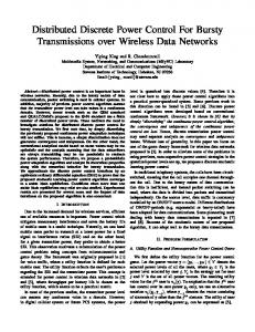
The controller card has a size of 130 mm x 85 mm and is implemented in surface mount technology. It is based on an INTEL 80C251SB microprocessor with 1K of internal RAM and 32K of external FLASH ROM and the 82527 CAN-bus interface. The analogue section contains one 16 bit DAC (Burr-Brown [2] DAC714) and one 20 bit, 4 channel, delta-sigma ADC (Burr-Brown ADS1213). The digital configuration contains 1 bit each for ON/OFF control and status read back. All analogue and digital I/O is optically isolated from the CPU and bus sections. A functional block diagram of the controller card is shown in Figure 1.
2 Design goals The TRIPS controllers were to be of small foot-print and “generic” in the sense that they could be used without change for all types of DC power supplies used at the ISAC facility. Therefore the number of digital control and status bits had to be flexible. One 16-bit DAC and two 16-bit ADCs were to be provided. Controller health and status was to be indicated via LEDs and a test mode was to be implemented, where the
3.2 Transition card The transition card is specific to a given type of power supply. It connects to the supply’s control connector and adapts to the supply’s geometrical dimensions. The card contains a 48-bit serial number chip with non-volatile RAM for storage of configuration parameters. Additional powersupply specific digital I/O which exceeds the basic capabilities of the controller card is implemented on this card by using the I2C serial bus [3] from the controller card connector. Our first transition card was also used to provide LED status indicators for small, “black box” power supplies (Glassman MJ series). In an installed system, the transition card is considered part of the power supply. It confers personality to the supply via the serial number and parameters stored in NV RAM. 3.3 Network Power to the TRIPS controllers (+24 V) is supplied via small eight-channel hubs in the same cable which carries
Status Display
NV RAM Serial Number
Embedded Microcontroller Intel 82C251 Digital Input/Output
CAN-bus Tranceiver
CAN-bus Controller Intel 82527
Isolated +/- 15 Volts Power Supply
Opto Couplers
4 Channel 22 Bit ADC
4 Channel 2 Pole Antialasing Filter
16 Bit DAC
Loop Back
Power Supply Transition Card
Fig. 1: Functional Block Diagram of the TRIPS Controller
the CAN-bus. RJ-45 Telco connectors and category 5 shielded twisted pair cable were used to avoid the high cost of the standard CAN-bus connectors.
seven bits encode the controller number which is addressed by EPICS or which sends a message. The remaining three bits of the message identifier encode the message type of the most common messages.
4 Software implementation
Table 1: CAN-bus message identifier format
4.1 Embedded software The embedded code was written using the Keil Development tools [4] for the Intel 80C251. The application code consists of a main supervisory loop for coordinating data transfers between the CPU and the peripheral hardware. All data transfers between the CPU, the CAN-bus controller and the serial DAC and ADC occur during interrupt. To improve the overall performance, and reduce interrupt latency, the interrupt routines were coded in assembler. The embedded software consists of 600 lines of C code and 160 lines of assembler code. 4.2 Communication protocol For integration of the TRIPS controllers into the ISAC control system, a simple application-layer protocol was developed. Although the controller is capable of using 28 bit message identifiers (CAN-2), we implemented this protocol with the 11-bit identifier of the CAN-1 specification. This decision was based on the capabilities of the EPICS supported TIP810 Industry pack [5]. The high order bit of the message identifier is used to identify the message source, 0 for the EPICS system, 1 for the TRIPS controller. This ensures that in the CAN-bus arbitration supervisory messages have bus-priority. The next
Bit # 10
9-3 2-0
Usage Message source: 0 = EPICS 1 = TRIPS Station number (0 reserved for beacon) Message type
Message type 2 is used to denote an auxiliary message group where the type is encoded as part of the data. The format of the message identifier used in our protocol is summarised in Table 1, message types are listed in table 2. Table 2: TRIPS Message Types: 0 .. 6 originate from EPICS 7 originates from the TRIPS controller Type 0 1 2 3 4 5 6 7
Message on/off new setpoint auxiliary command change deadband change update rate limit loop-back on/off configure Data Message (from controller)
On power up, the CAN-bus controller accepts all messages from the EPICs system until a configuration message is received for the serial number on this controller’s transition card. This configuration message provides the TRIPS controller its device number on the CAN-bus segment. From then on the controller responds only to messages addressed to this device number. The controller expects a broadcast beacon message, (addressed to device number 0) from the EPICS system at a programmable frequency. If the beacon is not received, the attached power supply is shut off. The controller transmits a data message on status or data change which is outside a programmable deadband. This data message is sent at least every 2 seconds, but not more often than 10 times per second. The data message contains one status byte, the DAC value and two ADC values. If the controller is put into diagnostic loopback mode, the power supply is switched off.
A network of 30 TRIPS controllers is currently in operation at the ISAC ion source test faciltiy [8] which runs a prototype of the future ISAC control system. All design goals were achieved. The expected savings in hardware, installation and documentation costs were fully realised.
5 Test facility
References
For commissioning of the TRIPS controller, a PC based diagnostics program was written to run under DOS. This tool uses a (MSMCAN) PC104 CAN-bus controller card [6] on an ISA adapter card.. Although not very sophisticated, this tool has proved very valuable for monitoring CAN-bus activity, listening to specific message identifiers etc.
[1] [2] [3] [4] [5] [6] [7] [8]
6 EPICS integration
In the supervisory EPICS based control system, a TIP810 Industry Pack on a Motorola MVME162 CPU is used to interface to the CAN-bus. The software integration of the TRIPS controller was straightforward due to the availability of EPICS device and driver level support for CAN-bus from the collaboration [7]. In our implementation, data messages from the controller are received under interrupt and the data package is transparently distributed to several EPICS records by the device support routines. 7 Conclusion
Robert Bosch GmbH, Stuttgart, Germany Burr-Brown Corporation. Tucson, Arizona. Phillips Components Division. Eindhoven, Netherlands Keil Software Inc. Dallas, Texas. Tews Datentechnik, Halstenbeck, Germany. Digital Logic AG, Luterbach, Switzerland. Andrew Johnson., http://www.ast.cam.ac.uk/~anj/epics R. Keitel et al., contribution P152 to this conference.