PowerMac machines, with shared memory biprocessor symmetric .... G4. [Arch_3]. PowerMac. G5. OS. Windows XP. Mac OS 10.3. Mac OS 10.3. Compiler.
MVA2005 IAPR Conference on Machine VIsion Applications, May 16-18, 2005 Tsukuba Science City, Japan
8-1 Real-time 2D Image Stabilization: Algorithmical Aspects and Parallel Implementation FábioDIAS,JeanPierreDERUTIN,LionelDAM EZ LASMEA - LAboratoire des Sciences et Matériaux pour l’Electronique et d’Automatique Université Blaise Pascal — Clermont-Ferrand — France 24AvenuedesLandais,AUBIERE Cedex–63177 dias,derutin,damez@ univ-bpclermont. fr Abstract We present a real-time image stabilization method, based on a 2D motion model and dif f erent levels of parallel implementation. This stabilization method is decomposed into three main parts. First, the image matching is determined by a f eature-based technique. Then the motion between consecutive f rames is estimated and f iltered to extract the unwanted motion component. This component is f inally used to correct (warp) the images,resulting in a stable sequence.To validate our stabilization approach in a real-time on-board system context,the algorithm was implemented and tested over dif f erent hardware platf orms, allowing a perf ormance evaluation in f unction ofthe adopted architecture.In this paper,we present some of the results concerning the parallel implementation using the SIMD ALTIVEC® instructions set and a symmetric multi-processor architecture (SMP). Keywords – 2D image stabilization, parallel implementation,real-time application,SIMD instructions, SMP architecture.
at t ent i on. However, i t ’s i mport ant t o simul at e t he al gori t hmi cal approach i n real i st i c experi ment al condi t i ons,speci al l yt imi ng condi t i ons.To achi eve t hi s t ask, t hi s ki nd of soft ware needs a speci al hardware archi t ect ure,wi t hparal l elprocessi ngabi l i t i es. Ourapproach t o dealwi t ht he“Al gori t hm-Archi t ect ure Adequat i on”i sbased on st andard comput at ionalsystems, al socal l ed“Commodi t yoft heShel f”(COTS).Int hefi rst st age of t he work,we have veri fi ed t he preci si on and robust nessofourmet hod i n asequent i alway.Then,i na second devel opment st age, we di d i t s real -t ime impl ement at i onusi ngt heparal l elst ruct uresofferedbyt he COTS syst ems. In sect i on 2,we descri be bri efl yt he di fferentexist i ng st abi l i zat i onmet hods,andal sot heprocessi ngbl ocswhi ch i on,we presenta general l y compose t hem.In t he3rd sect more det ai l ed descri pt i on of our st abi l i zat i on approach. Sect i on 4 present st he vari ous hardware st ruct ures we have adopt ed.Sect i on 5 expl ai nshow t he al gori t hm was programmed to be execut ed i n a paral l elway.Fi nal ly i n sect i on 6, we present some resul t s rel at ed t o t he impl ement at i onont hedi fferenthardwarepl at forms.
2-TheElectronic ImageStabilizati on 1-Introduction W earei nt erest edi nt hegeneralst udycaseofacamera ri gi dl ymount edonamobi l esyst em.Thi sconfi gurat i oni s frequent l y found i n t el e-operat i on or ai ded-dri vi ng syst ems. The image sequence from t his camera has i nformat i ons aboutt he movementof t he vehi cl ei n it s envi ronment . Thi s movement may be di vi ded i nt wo component s:oneduet ot hedri ven mot i on oft hevehi cl e, and a second component due t ot he parasi t e mot i on (uni nt ended) suffered by t he camera (bumpy ground, vi brat i ons,et c. ).Dependi ng on i t sampl it ude,t hi sparasi t e component can st rongl yi nt erfere i nt he vi sual i zat ion processandunderst andi ngoft heimagesequence,whet her i ti s by a human observer/ operat or,or by an art i fici al vi si onsyst em. In t hese si t uat i ons, st abi l i zi ng t he i mage sequence consi st si n el i mi nat i ng or smoot hi ng of t he uni nt ended moti on component , whi l el eavi ng t he dri ven mot i on componenti nt act .Thi sprocessi scal l ed “on-demand”or “sel ect i ve”st abi l i zat i on. Al t hough el ect roni c i mage st abi l i zat i on i s wi del y expl ored,t he archi t ect ural hardware approach al l owi ng t hesesyst emstoworki nreal -t ime,whi l erespect i ngal lt he speci fi ci t i es of an on-board syst em,has recei ved li t t l e 227
In t hel astyears,severalel ect roni cimagest abi l izat i on met hodswereproposed.Thesemet hodsmaybecl assi fi ed i nt ot hreemain fami li es,accordi ng t ot headopt ed mot i on model : 2D or pl anar methods [Mo97], 3D met hods [Dur03]and2, 5D met hods[Zhu98]. In fact , st abi l i zat i on al gori t hms are composed of a sequenceofprocessi ng bl ocs,whi ch havedi fferentl evel s ofcompl exi t y.General l y,t hreemai nprocessi ngst agesare compl et ed: image mat chi ng, gl obal mot i on processi ng usi ng t he adopt ed model ,and fi l t eri ng/ compensat i on of t heunwant edmoti on,get t i ngasresul tast abl esequence.
2. 1 - Image matching: W e aim to calculate the movementi nt he2D i magepl an ofareal -worl d poi ntor regi on.Thi smovementi st he2D project i onoft heobject ’s 3D mot i on i nt heobserved scene.Themostcurrentways t o sol ve t hi s probl em are t he opt i cal fl ow ext ract i on [Dur03]andfeat ure-basedapproaches[Mo97]. Eveni ft heopt i calfl ow ext ract i onmet hod(expl ai nedi n [Horn81] and [Bar94])has al ready been empl oyed for imagest abi l i zat i on purposes,i ti sconst rai ni ng becauseof i t smat hemat i calcompl exi t y(t hatmayberel at i vel yhi gh). The assumpt ion t hat t he opt i cal fl ow fi el ds are a 3D moti onfi el dsproject i oni sanot herconst rai nt[Ve89].
In this study, to process image matching we use detection and tracking of visual features. This method consists in two steps: first, searching in the image i for regions with strong visual information (e.g. strong luminance contrast, corners, edges, etc… ) called visual features, then identifying the same regions in the image i+1. Different tools for visual features detection are known, for instance, the “corner and edge detector” [Har88], the Laplacian operator and Harr' s wavelets (the latter is presented in the next section). Once our features have been detected, we must be able to find them in another image. This task is done using a correlation method combined with a search strategy. M ulti-resolution techniques allow a smaller processing time, through a “coarse-to-fine” approach. Several correlation methods may be employed, from the simplest ones being SSD & SAD [Pou02], to light-changes robust methods like normalized cross correlation [Tsai03].
detection by Harr’s wavelets, applied over a transformed image (integral image). The search of matching points is done using a multi-resolution pyramidal strategy, with three resolution levels. A SSD (Sum of Squared Differences) operator is applied to measure the similarity between the searched feature and its potential matching. Once we get matching points between two successive images, we can estimate the 2D motion model parameters ( x, y and θ), using the M edian Least Squares M ethod (M LSM ). This technique is powerful as it limits the influence of incorrect matchings that could be found in the previous stage. Finally, the movement parameters are filtered and the obtained unwanted motion component is used to warp the respective image, stabilizing the video sequence (figure 2). _
_
__
Detailed description: From each image acquired by the camera (coded in 256 grey levels, image size adjusted by the user) three intermediary images are produced: one integral image, that will be used for visual features detection, and two sub-sampled images (½ and ¼ pixels), used to construct the multi-resolution searching pyramid. The integral image has in its (X, Y) position the sum of all pixels inside the rectangle delimited by i(0, 0) and i(X, Y), where i(x, y) is the original image. The calculation uses the formulae of recurrence given below, where ii(x, y) is the integral image and s(x, y) is an intermediate value (sum accumulated line by line on column x):
2.2 - Global motion estimation: Once image matching has been achieved we can proceed to the second stage of the stabilization processing chain: the estimation of the motion parameters, which are determined by the adopted motion model. 2D models suppose a planar or almost planar scene. All points tracked in the preceding stage must lie in approximately the same distance from the camera. In this case, there are three parameters to estimate: two translations (horizontal and vertical) and one rotation around the camera optical axis. A fourth parameter may be included, to take into account scale changes caused by the camera forward/backward motion. 3D models suppose that only rotational parasites are relevant. So, we have to estimate and correct 3D rotations to stabilize our image sequence. Knowing that camera rotation effects in images are independent from scene depth, we are able to estimate camera rotation parameters, using quaternions for instance [Mo97]. The 2.5 model presented in [Zhu98] presuppose the availability of preliminary information about camera motion leading us to estimate three global motion parameters, plus one independent parameter for each analysed point (tracked). This last one is a depth-related parameter. It allows us to work with structurally sophisticated scenes, without needing an advanced 3D model.
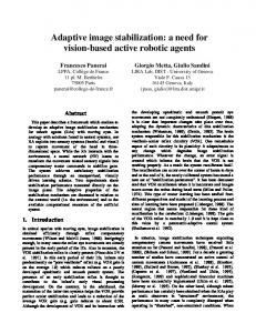
s(x, 0) = i(x, 0) s(x, y) = s(x, y - 1) + i(x, y) ii(0, y) = s(0, y) ii(x, y) = ii(x - 1;y) + s(x, y) Harr' s wavelet processing consists in the convolution between an image region (pattern) and one wavelet mask (figure 1). The obtained value represents the luminance gradient in a given direction. Wavelet’s processing is strongly accelerated when using an integral image. In this case, we can evaluate the sum of all pixels inside a rectangle of any size performing only 4 memory access and 3 sum operations [Vio01]. This property is also exploited for sub-sampled images creation. The mean value of pixels inside a square region (size 2x2 or 4x4) of the original image is obtained using the integral image.
2.3 - M otion compensation: Finally, after estimating the global motion between images, we’re going to compensate its unwanted or unintended component. This last processing stage is closely related to the application framework. The definition of “unwanted motion” depends entirely from the kind of “stability” required in each application. Several methods can achieve "full compensation"corresponding to static background scene, low-pass or inertial filtering [Zhu98] and low-order polynomial fitting for 3D rotations [Dur03].
Figure 1. Three examples of wavelet masks. Features are detected applying the wavelets over a predefined zone. We use the upper half of the image to search features present in the horizon line. Normally, these regions are far away from the camera, enough to respect the planarity constraint of the 2D motion model. The detection zone is divided in n/ 3 vertical bands, n being the desired features number, set by the user. Three types of wavelets (vertical, horizontal and diagonal) are applied into each band, and the three regions presenting the
3- Our Stabilization M ethod General description: We have developed a stabilization method based on a 2D motion model, with visual features 228
Figure 2. Synoptic scheme of the stabilization algorithm. biggest values of vertical, horizontal and diagonal gradients respectively are selected as features (figure 3). After the detection stage in image i, we seek the n corresponding features in image i+1. A "search window" with size 2Tx2T is defined around the position where a feature was detected. The SSD is calculated between each region inside this window and the feature selected in image i (figure 3). The region in image i+1 which minimizes the SSD is considered to be the match of the respective feature. This operation is repeated for each one of the n features detected in the preceding stage, giving us n matching points between two successive images. T is the largest feature displacement, between two images, that can be measured by the system. This configurable parameter directly influences processing time, searching time being linked (non linearly) to the distance T. This obvious bond between the largest displacement and the processing time is extremely important. The goal is to maximize the multiplication of the largest displacement (in pixels) by the number of images processed per second. This indicates the greatest speed of an object (in pixels per second) that the system can deal with. This way, the parameter T must be carefully set, taking into account its influence on the processing time.
To reduce the processing load, the search for matching features is executed in a multi-resolution approach. We start using a ¼ sub-sampled image, and looking for a SSD minimization inside a T/2 x T/2 window. This provides us with a first estimation for the matching point position. Based on this estimation, a second search process begins, using a ½ sub-sampled image and a 3x3 search window, placed around the first estimated position. A second estimation is thus obtained, more accurate than the first one. Finally, the final search stage is executed, using the original image and a sub-pixel precision of 1/8 pixel. A 2x2 search window is analysed, and the value of regions lying between pixels is calculated through a bilinear interpolation of the adjacent pixels. Having found the n points matching between images i and i+1, we can estimate the 2D motion model parameters describing the movement from one image to other. This movement can be modelled by a homogeneous transformation matrix, composed of a rotation around the optical axis, vertical and horizontal translations. Three matrix parameters, related to each of these movements, must be estimated. The n point matching result is applied to the model, and the error is minimized using the Median Least Squares Method. The motion parameters obtained are added to those processed before, in order to find the total camera movement from the beginning of the video sequence. The found values are filtered by first-order linear filters. Each parameter has an independent filter, and the coefficients of all filters can be set by the user. This method allows us to have flexible stabilization intensity, adjustable to the application. We can also have different stabilization levels for translations and rotation. The filtered values are used to get the inverse homogeneous transformation matrix that is applied to stabilize image i+1, bringing it back to a dynamic reference position (figure 4). This dynamic reference position tries to follow the commanded camera motion, respecting the passing band determined by the coefficients of the filter.
Figure 3. Features detection (left) and tracking (right).
229
The utilisation of SIMD instructions implies a fine grain parallelization, recommended for repetitive operations. In this case, if the “operations/memory access” ratio is high enough, we can have almost linear speed-up factors (4, 8 or 16) when processing integer type of data, or even over-linear speed-up factors for floating point type of data. The performances obtained with this type of parallelization are discussed in [Fal04]. However, the SIMD parallelization is limited to the framework of repetitive regular operations. Another inconvenient is that it imposes a low abstraction level, and it’s necessary to completely rewrite the software code for that tasks we hope to accelerate.
Figure 4. Stabilization of a synthetic sequence. This stabilization method was tested with several real and synthetic incoming video sequences. The obtained precision for synthetic sequences (for which ground truth information is available) is very accurate. The motion parameters estimation between two successive images has mean error of 0.2 pixels for translations estimation, and 0.05 degrees for rotations. The synthetic sequences were produced from a real road image (figure 3) and applying on it successive 2D rigid transformations in order to simulate the camera motion (figure 4). The camera motion model was extracted from a real sequence took in off-road conditions.
4.2 - SMP architecture: The second level of parallelization lies on the exploration of two processors communicating via a shared memory. The use of this type of architecture results in a big grain parallelization, sharing the tasks or the data between both processors. The operation system (MacOS X) manages the executing tasks distribution in a “preemptive” way. It’s also conceived to share the tasks between both processors, making the parallel processing transparent for the user. However, in order to execute a same task over two processors simultaneously, we must split this task in lighter processes called “threads”. In our case, two threads are created and executed at the same time, enabling the system to distribute the work between the available processing resources. The creation of these threads is possible using the standard functions library “pthread”. This library defines some rules and tools for threads creation and fusion, including locking functions to manage tasks synchronization and mutual exclusion. Otherwise parallelization through SIMD instructions, this type of parallelization allows a high abstraction level, enabling a fast implementation without entirely rewriting the software code.
4 – Hardware Presentation The processing chain descrided in section 3 was developped on a PC machine, featuring a AMD Athlon XP 1700processor. After the evaluation and validation of algorithm’s efficiency, and in order to enable a real-time processing, the application was transferred toward Apple PowerMac machines, with shared memory biprocessor symmetric architectures. These machines have two processors Motorola MPC7455 (PowerG4) or two IBM PowerPC 970 (PowerG5). The operation system is MacOS X. The selected systems have some features enabling parallel processing, in two different levels: • Inside each processor, through super scalar processing devices, and with SIMD instructions set (Altivec). • With two parallel processors working simultaneously, sharing the machine’s memory (SMP architecture).
5– Parallel Implementation To propose a parallelization scheme exploiting to the best the hardware features introduced in the previous section and presenting good timing performances, we adopted the following methodology: the different processing stages of the sequential version were carefully analysed, according to two different criteria: “operations/memory access” ratio and processing data volume. Based on this analysis (table 1), we tried to concentrate the parallelization efforts on that stages where the speed gain may be potentially high. From this analysis, we can assume that step_1, step_2 and step_4 are the most processing consuming stages. The relative importance (in sequential processing time) of these stages in relation to the whole stabilization loop is shown in table 2. It’s noticeable that step_4 is the most time consuming task. However, when image size is increased, intermediary images creation (step_1 and step_2) becomes a time consuming task too. So, in order to obtain a noteworthy speed-up factor, it’s interesting to execute these three tasks with a parallel approach.
4.1 - SIMD instructions set: This type of extension is found in several microprocessor families: MMX, SSE and SSE2 for Intel processors, 3DNOW!for AMD, MDMX for MIPS and VIS for SPARC processors. All these extensions of the instructions set are based on two principles: • first principle: it offers SIMD processing capacities, making possible to execute a logical or arithmetical operation on a multiple data set, with one instruction only. • second principle: it gives a set of instructions strongly inspired by DSP systems: satured arithmetics, cabled and type conversion operateurs. These instructions are applied on fixed size vectors (128 bits for Altivec), but the number of processed elements inside a vector can vary: four 32 bit, eight 16 bits or sixteen 8 bits elements. 230
The second parallelism level is in the correlation computation. SSD results are obtained using Altivec SIMD instructions. We are able to process up to 16 pixels in only one operation and in this case, we have 16 times less operations to process. The SIMD function for SSD computation exists in two different versions: a simpler one, working with integer type data, and a more complex second version, dealing with floating-point numbers and bilinear interpolations.
Table 1. Decomposition and potential parallelism of each step of the algorithm. Processing Stage
step_1: Integral Image Processing step_2: Sub-sampled Images Processing step_3: Features Detection step_4: Features Matching step_5: Motion Parameters Estimation step_6: Motion Filtering and Correction
Intrinsic parallelism
Operations /memory access
Processing data volume
data
low
high
tasks and data
low
high
low
low
very high
very high
sequential
low
low
sequential
low
very low
tasks and data tasks and data
• After the tracking stage, matching points lists of both processors are merged, and the motion model parameters are estimated and then filtered (step_5and step_6). These two last stages, not presenting a relevant complexity, are processed in sequential mode. Table 3. Characteristics of the used machines. [Arch_1] [Arch_2] [Arch_3] System
OS Compiler µP number µProcessor Frequency Memory size Cache size L1 L2 L3
Table 2. Relative importance of the steps 1, 2 and 4. Processing Stage
step_1 and step_2: Intermediary Images Processing step_4: Features Matching
Image 320x240
Images 640x480
Images 1280x960
3%
12%
24%
93%
81%
65%
5.1 - Parallel implementation on a shared memory biprocessor symmetric architecture: As explained
Athlon XP 1700+ Windows XP gcc 3.2 1 Athlon XP 1,47 GHz 512 Mo
PowerMac G4 Mac OS 10.3 gcc 3.3 2 MPC7455 1 GHz 512 Mo
PowerMac G5 Mac OS 10.3 gcc 3.3 2 PowerPC970 2 GHz 1Go
128 Ko 256 Ko
64 Ko 256 Ko 1 Mo
64 Ko 512 Ko
6– Results
before, these machines have two potential types of parallelism: data parallelism through vectorial instructions (Altivec library, SIMD mode), and data or task parallelism through biprocessor architecture (SMP mode).
The temporal performances of the stabilization algorithm were measured with 3 image sequences with sizes 320x240 (bench_1), 640x480 (bench_2) and 1280x960 (bench_3). The software was configured to search n = 42 visual primitives at a maximal distance T near to 5% of image size: T = 15 pixels for bench_1, 30 pixels for bench_2 and 60 pixels for bench_3. Characteristics of the machines used for tests are shown in table 3. In tables 4 and 5 we present the execution time of the parallelized functions and of the whole stabilization loop (step_1 to step_6). Measures correspond to the delay between two system time function calls, averaged over 1000 iterations of the stabilization loop. With 320x240 images (table 4), we obtain a very satisfying speed-up factor on step_4 (around 12), due to the SIMD mode, making possible to stabilize images in less than 10ms, using only one processor. SMP mode has a weak theoretical speed-up due to the number of processors (only 2). On step_4, speed-up is almost linear with approximately 1,9 for Arch_2 and Arch_3. For step_1 and step_2, it is higher on Arch_3 (approximately 1,8) than on Arch_2 where it varies between 1,4 and 1,7. The processing time of step_3 remains short in comparison with the whole stabilization loop. Even if SMP mode does not compensate the increasing complexity of step_1 and step_2 with image size augmentation, the final speed-up is at least 3 for Arch_2 and 5 for Arch_3.
• The integral image creation (step_1) is processed in SMP mode. Image is divided in two equal horizontal bands, and the integral of each band is calculated by one processor. The image division causes a data dependence break. In consequence, an extra correction stage must be executed to achieve the complete integral image. • Sub-sampled images are calculated from the integral image (step_2), and are completely independent one from the other. So, a SMP mode is employed, with each processor being responsible for one sub-sampled image creation. • Features detection (step_3) is done in SMP mode, using the division in vertical bands, like explained in section 3. Each processor searchs the half of the desired features number (n/2), processing the half of the n/3 vertical bands that were defined inside the detection zone. • In the sequential analysis (tables 1 and 2) we noticed that the features matching stage (step_4) is the most time consuming task. So, it brings two parallelism levels in its parallel implementation. Each processor searches the matching for that features it own has previously detected. So, each processor is therefore responsible for tracking the half of the desired features number (n/2).
231
Table 4. Temporal performances (in ms) for Arch_1, Arch_2, and Arch_3 with bench_1 parameters: image size 320x240, n = 42 primitives and T = 15 pixels. Processing stage
step_1 and step_2 step_3 step_4 Total (step_1 to 6)
[Arch_1] sequential 1,4 0,3 33,2 37,1
[Arch_2] sequential 2,1 0,3 56,7 61,7
[Arch_2] SIMD 2,1 0,3 4,7 9,7
[Arch_2] SIMD + SMP 1,5 0,2 2,5 7,9
[Arch_3] sequential 0,9 0,2 31,1 33,3
[Arch_3] SIMD 0,9 0,2 2,6 4,9
[Arch_3] SIMD + SMP 0,5 0,1 1,4 3,8
Table 5. Temporal performances (in ms) for each implementation with Arch_2 and Arch_3. Left side shows results for bench_2 parameters (image size 640x480, n = 42 primitives and T = 30 pixels) and right side shows results for bench_3 parameters (image size 1280x960, n = 42 primitives and T = 60 pixels). Processing stage
[Arch_2] sequential
step_1 and step_2 step_3 step_4 Total (step_1 to 6)
9,7 0,9 66,8 82,7
[Arch_2] SIMD + SMP 5,8 0,7 4,0 17,1
[Arch_3] sequential
3,8 0,4 37,8 44,0
[Arch_3] SIMD + SMP 2,1 0,3 2,0 6,9
[Arch_2] sequential
40,3 1,8 108,2 166,4
[Arch_2] SIMD + SMP 25,1 1,0 8,0 51,6
[Arch_3] sequential
15,8 0,7 83,2 105,2
[Arch_3] SIMD + SMP 8,8 0,5 2,8 20,4
7 – Conclusions and Future Work
8 – References
This paper presents an efficient method for 2D image stabilization with a precision near the 1/5th of pixel. Furthermore, the originality of features detection by Harr's wavelets using an integral image allows an important decreasing in the number of operations, which allied to the efforts of parallel processing gives very fast temporal performances. Very high speed-up factors were obtained with parallel processing, particularly using the SIMD instructions set. Processing time was drastically reduced, making possible to use this stabilization method as initial (pre-processing) stage in a chain of artificial vision algorithms. We’re able to deal with big format images (1280x960), in real-time, using only a commercial (COTS) system, instead of an expensive dedicated architecture. The parallel implementation of this stabilization method was led as pre-study for algorithms dedicated to the old films restoration (working with very big size images). Further optimizations are possible. Processing regions of interest corresponding to detection bands in step_1 and step_2, instead of processing whole images should reduce operations number and avoid the data dependency correction described in part 5.1. The implementation of an optimized version of this same stabilization method on a MIMD-DM architecture has already been led, and the obtained results will be shown in our next publication [Der05]. We used a cluster of 14 biprocessor PowerG5 machines, interconnected thru a 1 Gbit Ethernet network, and communicating via message passing, using the MPI library. This last implementation has been studied for a future implementation of this algorithm in an electronic chip, using a network of communicating homogeneous processors and SPMD approach.
[Bar94] J. Barron, D. Fleet, S. Beauchemin and T. Burkitt. “Performance of optical flow techniques”. International Journal of Computer Vision, 12(1) : 43-77, 1994. [Der05] J. P. Derutin, F. Dias, L. Damez and N. Allezard. “SIMD, SMP and MIMD-DM parallel approaches for real-time 2D image stabilization”. International Workshop on Computer Architecture for Machine Perception CAMP’2005, July 2005. [Dur03]Z. Duric and A. Rosenfeld. “Shooting a smooth video with a shaky camera”. Machine Vision and Applications, 13 : 303-313, 2003. [Fal04]J. Falcou, J. Serot. ”E.V.E., An object oriented SIMD Library”. International Conference on Computational Science ICCS’2004, Part 3, pages 323-330, 2004. [Har88]C. Harris and M. Stephens. “A combined corner and edge detector”. Proceeding of the 4th Alvey Vision Conference, pages 147-151, 1988. [Horn81]B. Horn and B. Schunck. “Determining optical flow”. Artificial Intelligence, 17 : 185-204, 1981. [Mo97]C. Morimoto. “Electronic Digital Stabilization: Design and Evaluation, with Applications”. PhD thesis, 1997. [Pou02]H. Pourreza, M. Rahmati and F. Behazin. “Weighted multiple bit-plane matching, a simple and efficient matching criterion for electronic digital image stabilizer application”. 6th International Conference on Signal Processing, 2 : 957-960, 2002. [Tsai03] D. Tsai, C. Lin and J. Chen. “The evaluation of normalized cross correlations for defect detection”. Pattern Recognition Letters, Vol. 24, pages 2525-2535, 2003. [Ve89]A. Verri and T. Poggio. “Motion field and optical flow: Qualitative properties”. IEEE Trans. Pattern Analysis and Machine Intelligence”, 11(5) : 490-498, 1989. [Vio01]P. Viola and M. Jones. “Rapid object detection using a boosted cascade of simple features”. Proceedings IEEE Conference On Computer Vision and Pattern Recognitinion, 2001. [Zhu98] Z. Zhu, G. Xu, Y. Yang and J. Jin. “Camera stabilisation based on 2.5D motion estimation and inertial motion filtering”. International Conference on Intelligent Vehicles, 1998.
232