影像與識別 2006, Vol.12 No.4
Image Stabilization System on a C…
Image Stabilization System on a Camera Module with Image Composition Yu-Mau Lin, Chiou-Shann Fuh Department of Computer Science and Information Engineering, National Taiwan University, Taipei, Taiwan, 10617, R.O.C
[email protected]
Abstract. With the boosting of number of image sensor’s pixels and the compacter working volume of today’s digital still camera or camera phone, the need for better image quality has soared and drives more newly designed image processing techniques. Image stabilization, one of these newly techniques, plays an essential role in today’s camera design. We propose a digital image stabilization algorithm based on an image composition technique using four source images. By using image processing techniques, we are able to reduce the amount of image blur and compose a sharper image from four source images. Keywords: Image stabilization, image composition.
1
Introduction
Both DSC (Digital Still Camera) and camera module of the cellular phone are playing more and more essential roles of human daily life. They need to demand more handy functions and finer image quality, yet smaller device volume relatively. On DSC side, numerous image stabilization systems are introduced, by mechanical system or by software processing, and they all work well to reduce handshake blur. On camera module side, however, mechanical solutions are infeasible due to the extra space it needs, and space is precious in a small device like a cellular phone. As a result, software processing seems to be more attractive for its lower cost and smaller size. Hence, our algorithm will be a softwarebased image stabilization system optimized for camera module. 1.1
Causes of blurred image
Generally speaking, blurred images can be classified into three different types: focus blur, motion blur, and hand-shake blur [14]. Understanding the kinds of blur is important for giving us better sense of the solutions. Out-of-focus blur needs a better AF (Automatic Focus) algorithm. Moving object blur needs faster shutter speed to freeze the object’s motion. As for hand-shake blur, a tripod or image stabilization system would be useful. 1.2
Formation of blurred image
One cause of blurred image is slow shutter speed. Shutter speed is a measurement of how long camera’s shutter remains open as the photo is taken. The slower the shutter speed, the longer the exposure time. A slow shutter speed can blur the movement or scene on purpose as artistic effect, but can also bring unwanted hand-shake blur more visible. Another reason for blurred image is telephoto shots, which means photographs taken by long focal length lenses. A telephoto lens has a long focal length and narrower field of view than a normal lens and enlarges distant subjects. When taking photos with a telephoto lens, all the objects in the scene are magnified in size, and if the assistance of a tripod is absent, even a small hand-shake will cause a significant blur in the image.
- 40 -
影像與識別 2006, Vol.12 No.4 1.3
Image Stabilization System on a C…
Gradient Magnitudes
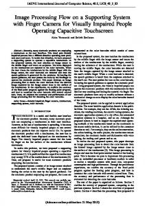
When judging how robust an image stabilization algorithm is, the resulting images are analyzed for benchmarking. We need an impartial tool to determine whether a given image is blurred, and how blurred it actually is. Therefore, the idea is to examine the image’s edge. Edges represent high frequency components, and the sharpness of the edges can be used to judge the contrast of the image. One commonly used edge detector is Sobel (1970) edge detector [8], which is a combination of horizontal and vertical kernels s1 and s2, as illustrated in Fig. 1.1.
⎡ − 1 0 1⎤ s1 = ⎢⎢− 2 0 2⎥⎥ ⎢⎣ − 1 0 1⎥⎦
2 1⎤ ⎡1 ⎢ s2 = ⎢ 0 0 0 ⎥⎥ ⎢⎣− 1 − 2 − 1⎥⎦
(a) Detect vertical edge.
(b) Detect horizontal edge.
Fig. 1.1 Sobel edge detector.
Let s1 be the value calculated from the first kernel, and s2 the value calculated from the second kernel, the gradient magnitude g is defined by Equation (1.2):
g = s1 + s 2 2
(1.2)
2
We will adopt Sobel edge detector to calculate image’s gradient magnitude, for its faster computation time.
2
Digital Image Stabilization
The optical compensation systems can provide excellent performance, but they add cost and weight to the design. Dissimilar to optical (mechanical) image stabilization, digital (electronic) image stabilization does not require extra hardware backing components like moving lens or prisms, but rather use digital image processing techniques to bring up sharper images, and therefore is less costly. 2.1
Digital Image Stabilization by Moving Window
This approach is best applied in a system having large-sized CCD. The subject image that the objective lens focuses onto the CCD is smaller than the CCD itself. Thus, the image floats on the CCD plane as the camera jitters and is not truncated or clipped as it shifts due to camera shake. At the same time, motion sensors tell the system which way the camera is moving, so the signalprocessing circuitry can digitally implement a compensating shift on the captured image data. Again, the system needs to use algorithms that try to adjust the compensation parameters to account for various real-world conditions and types of image motion. 2.2
Digital Image Stabilization by Higher ISO Speed
Another sort of digital image stabilization is achieved by raising the ISO speed up to ISO 640, ISO 800, or higher setting, to allow faster shutter speed while taking the shot. However, this approach is de facto a trade-off between image blur and image quality, because it magnifies channel gain values and results in worse SNR (Signal to Noise Ratio) performance. Many DSC or camera module vendors, however, are putting more efforts on noise reduction techniques, and incorporate higher ISO speed image stabilization along with stronger noise reduction techniques, making this approach more feasible for practical use. 2.3
Digital Image Stabilization on Camera Phone
NTT (Nippon Telegraph and Telephone Corp.) DoCoMo (Do Communications Over the Mobile Network) released a mobile phone, FOMA (Freedom of Mobile Multimedia Access) N902i, with a 2- 41 -
影像與識別 2006, Vol.12 No.4
Image Stabilization System on a C…
megapixel CCD camera equipped with digital image stabilization on November 18, 2005. The handset is developed and manufactured by NEC Corp. This is the first camera phone with image stabilization on the market. As claimed on NEC’s website, the image stabilization is done through the following sequences: first, four still images are shot within the exposure time required to shoot one image when using other existing cameras. This means that although each of the four images lacks exposure, image blur caused by camera shake is reduced since the shutter speed becomes faster. In the subsequent step, the four images are superimposed after feature extraction processing is carried out for each image. Based on the results of the processing, images are aligned so as not to be offset with respect to one another [16].
3
Image Stabilization with Image Composition
The goal of image stabilization is to reduce the blur in the image. The aforementioned J. F. Chen’s Super Resolution Reconstruction uses two input images, both are taken by accurate exposure, to reconstruct a sharper image by combination. If the two input images are only partially blurred and are complement to each other, this algorithm works well and would produce a sharper image. The drawback of this algorithm, however, is when the two input images are all blurred, the combined image will be just as blurred as the input images. In summary, our algorithm will: 1. model the camera’s motion as Euclidean, i.e. rotation plus translation; 2. reduce the blur in each input image; 3. increase feature match accuracy; 4. speed up the computation time. Here, the idea of our algorithm is to take four consecutive images, all of them are under-exposure images with a four times faster shutter speed of a proper exposure shutter speed. For example, if a properly exposure image needs f/2.8 aperture and 1/15 seconds shutter speed, we will take four consecutive images by f/2.8 aperture and 1/60 seconds shutter speed, which is four times faster, instead. The next step is to combine those images into a sharper single image, in the same sense with NEC FOMA N902i’s idea. The reason of under exposure image is that it allows user to capture photos with a higher shutter speed, and hence to reduce the amount of blur in each image. Our algorithm then applies feature detection, feature matching, and image composition to get the result image. 3.1
Feature Detection Using SIFT (Scale-Invariant Feature Transform)
In the first step of our algorithm, we will find feature points in each of the four images, and we uses SIFT [11] to find and describe feature points. SIFT, devised by David Lowe in 2004, and has U.S. Patent: 6,711,293 [12], is a scale-invariant feature detector, which is a carefully designed procedure with empirically determined parameters for the invariant and distinctive features. SIFT features are invariant to image scale, rotation, and partially invariant (i.e. robust) to changing viewpoints, and change in illumination. The name scale-invariant feature transform was chosen, as the algorithm transforms image data into scale-invariant coordinates relative to local features [18]. An important aspect of SIFT is that it generates large numbers of features that densely cover the image over the full range of scales of locations. According to the paper, a typical image of size 500x500 pixels will give rise to about 2000 stable features. Compared with Harris Corner Detector, SIFT offers much more features, and this is particularly important for our algorithm to produce a seamless work of image composition. There are four main steps in computation of SIFT features: 1. Scale-space extrema detection, 2. Keypoint localization, 3. Orientation assignment, 4. Keypoint descriptor. The first and second steps are used as feature detection, while the third and fourth steps are for feature descriptor generation. 3.2
Feature Matching
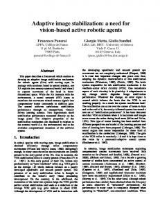
After brightening the input images and finding their SIFT features, we are going to match features in all of the four images, an input example is illustrated in Fig. 3.1.
- 42 -
影像與識別 2006, Vol.12 No.4
Image Stabilization System on a C…
(a) Image1, 2546 features.
(b) Image2, 2433 features.
(c) Image3, 2602 features.
(d) Image4, 2546 features.
Fig. 3.1 Input images and SIFT features.
Every SIFT feature descriptor is a 128-deminsional array, and is orientation-invariant. For every feature in an image, we want to find its match in the other image. We compute dot products between two unit vectors. Furthermore, the ratio of angles (arc-cosine of dot products of unit vectors) is a close approximation to the ratio of Euclidean distances for small angles. As a result, by finding the smallest value of the ratio of angles, we are able to match features in two images. However, if a feature in one image has no ground truth match in the other image, it can still find a match in anther image, i.e. this match is an outlier. To remove outliers in our feature matching result, we calculate the average of match pairs’ motion vector. If a match’s motion vector is greater than average_motion_vector+20 pixels or smaller than average_motion_vector-20 pixels, we regard this match an outlier and remove it from our match results. 3.3
Pre-Rotation
We want to avoid the misalignment effects caused by translation, and hope to improve the image composition quality and accuracy. For this reason, we model the camera’s motion as Euclidean, which is translation plus rotation [6]. Now we want to solve this Euclidean matrix between two images. To achieve this, we need to have match coordinates in two images. Therefore, we need to use SIFT to find features in both images, and use our feature match algorithm to find match pairs. Then, we have corresponding match pairs, and also their coordinates. By expanding matched coordinates into matrix form, we will have the following formula: ⎡ x1 ' x 2 ' x 3 ' ... x n '⎤ ⎡cos θ − sin θ T x ⎤ ⎡ x1 x 2 x 3 ... x n ⎤ ⎢ y ' y ' y ' ... y '⎥ = ⎢ sin θ cos θ T ⎥ • ⎢ y y y 3 ... y n ⎥⎥ 2 3 n ⎥ y⎥ ⎢ 1 2 ⎢ 1 ⎢ ⎢⎣ 1 1 ... 1 ⎥⎦ 0 1 ⎥⎦ ⎢⎣ 1 1 1 1 ... 1 ⎥⎦ ⎢⎣ 0
which equals to: Z=E*M. Using the relationship listed above, we want to calculate the Euclidean matrix E in this overdetermined system. By calculating matrix M’s pseudo-inverse matrix M-1, we multiply M-1 on both right side of the equation above for: Z * M-1 = E * M * M-1 , E = Z * M-1. Thus, to calculate Euclidean matrix E is equal to calculating Z * M-1.
- 43 -
影像與識別 2006, Vol.12 No.4 3.4
Image Stabilization System on a C…
Binary Tree Image Composition
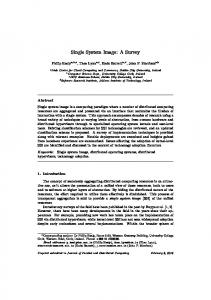
After pre-rotation, we will apply image composition in four source images. In our algorithm, we want to compose our images from four input images in a bottom-up, binary tree order, as shown in Fig 3.2. Final image Image 1-2
Image 1
Image 3-4
Image 2
Image 3
Image 4
Fig. 3.2 Binary tree construction of final image.
To compose an image using Images 1 and 2, we use a similar idea to J. F. Chen’s image combination, which is to divide the image into many rectangular patches. For every patch, if there are features located in this patch, the motion vector of this patch will be assigned as the average of the motion vectors between these features and their match pairs. However, if there is no feature located at this patch, we will temporarily assign the motion vector as null. After all patches have been calculated, for those patches without motion vectors, we apply nearest neighbor expansion to fill blank motion vectors. At last, every patch will have its own motion vector.
4
Conclusion and Future Work
We will discuss some difficulties we encountered with our algorithm, and conclude the possible future work on these aspects. 4.1
Dark Image Feature Detection
Due to the shorter exposure time, our source images are darker by -2EV, and this fact adds difficulties to our feature matching, for we can only locate fewer feature points compared with a properly exposed image. In our algorithm, we use gamma function to raise the number of features. In some cases, however, this approach seems to be unfeasible because the image is too dark and dominated by noise. Thus, how to find enough features in under exposed image is a future research direction. 4.2
Speed up Feature Matching
In our algorithm, almost 70% percent of computation time is consumed by feature matching, as is in proportion to the number of feature points. In our algorithm, we use arc-cosine of unit vector’s dot product to approximate Euclidean distance between two SIFT feature points, as suggested by the author of SIFT. If there is a faster or more efficient feature matching algorithm incorporated in our system, the computation time could be substantially reduced. 4.3
Image Composition
According to our experimental results, if matched pairs between two images are insufficient, the result image will suffer from blocking effects, because too few match pairs are used to calculate our patch vector map. In our algorithm, we use nearest neighbor expansion and the result depends partially on how many match pairs we have. Thus, if we are able to improve the accuracy of this part, our algorithm will be much more robust even our sources images are too dark to find sufficient amount of features.
- 44 -
影像與識別 2006, Vol.12 No.4
Image Stabilization System on a C…
Acknowledgement This research was supported by the National Science Council of Taiwan, R.O.C., under Grants NSC 94-2213-E-002-032 and NSC 93-2213-E-002-073, by the EeRise Corporation, EeVision Corporation, Machvision, Tekom Technologies, IAC, ATM Electronic, Primax Electronics, Scance, Lite-on and Liteonit.
References 1. [J. F. Chen, “Image Stabilization with Best Shot Selector and Super Resolution Reconstruction,” Master Thesis, Department of Computer Science and Information Engineering, National Taiwan University, 2005. 2. Y. Y. Chuang, “Feature Matching,” http://www.csie.ntu.edu.tw/~cyy/courses/vfx/05spring/lectures/handouts/lec04_feature.ppt, 2005. 3. CNET, “CNET Glossary: Image Stabilization (Optical, Electronic) - CNET Reviews,” http://reviews.cnet.com/4520-6029_7-6160688-1.html, 2006. 4. Dpreview, “Minolta DiMAGE A1 Review 1. Introduction: Digital Photography Review,” http://www.dpreview.com/reviews/minoltadimagea1/, 2003 5. EDN, “Image Stabilization Shows Diversity of Engineering Approaches - 10-26-2000 – EDN,” http://www.edn.com/article/CA47280.html#ref, 2000. 6. R. C. Gonzalez, R. E. Woods and S. L. Eddins, Digital Image Processing using MATLAB, Prentice-Hall, Upper Saddle River, New Jersey, 2004. 7. C. Harris, M. Stephens, A Combined Corner and Edge Detector, Proceedings of Alvey Vision Conference, Manchester, England, pp. 147-151, 1998. 8. R. M. Haralick and L. G. Shapiro, Computer and Robot Vision, Vol. I, Addison Wesley, Reading, MA, 1992. 9. Howstuffworks, “Howstuffworks: How Gyroscopes Work,” http://www.howstuffworks.com/gyroscope.htm, 2006. 10. Konica Minolta, “KONICA MINOLTA, Anti-Shake Technology,” http://konicaminolta.com.hk/ph/eng/products/photographic/dc/detail_7d.html 11. D. G. Lowe, “Distinctive Image Features from Scale-Invariant Keypoints,” International Journal of Computer Vision, Vol. 60, No. 2, pp. 91-110, 2004. 12. D. G. Lowe, “Method and Apparatus for Identifying Scale Invariant Features in an Image and Use of Same for Locating an Object in an Image,” United States Patent# 6711293, 2004. 13. NEC, “N902i-NECワイワイもばいる-カメラ,” http://www.n-keitai.com/n902i/cmr.html, 2005. 14. Nikon Imaging, “Nikon Imaging | Vibration Reduction,” http://nikonimaging.com/global/products/digitalcamera/coolpix/cppf/eng/vr_index.htm, 2006. 15. Panasonic, “Technology that LUMIX takes the shake out,” http://panasonic.co.jp/pavc/global/lumix/technology/index.html, 2005. 16. Phoneyworld, “NTT Docomo's FOMA N902i, with Image stabilizer,” http://www.phoneyworld.com/newspage.aspx?n=1567, 2005. 17. Wikipedia, “Gradient,” http://en.wikipedia.org/wiki/Gradient, 2006. 18. Wikipedia, “Scale-Invariant Feature Transform,” http://en.wikipedia.org/wiki/Scaleinvariant_feature_transform, 2006.
- 45 -