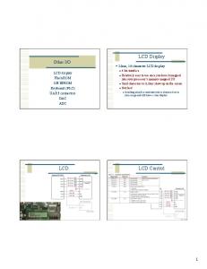
2-line, 16 character LCD display ... displayed. ○ Two rows of 16 characters to
display. ○ Also 24 extras per line that ... But, these are easily done in an
assembly.
Feba Electronics can repair LCD TFT panels from 3,5 inch up to 32 inch. ...
phones, computers, televisions, industry machine and other digital equipment.
LCD and Plasma display technologies are promising solutions for large-format ...
The Pioneer Plasma Display PDP-503CMX totals 1280 x 768 pixels with a ...
This Class B digital apparatus complies with Canadian ICES-003. ..... Auto Image Adjust automatically sizes, centers, an
May 30, 2004 - Macintosh and Power Macintosh are registered trademarks of Apple ..... service on ViewSonic products sold
May 30, 2004 - Macintosh and Power Macintosh are registered trademarks of Apple Computer, Inc. Microsoft, Windows, Windo
Macintosh and Power Macintosh are registered trademarks of Apple Inc. Microsoft, Windows, Windows NT, and the .... conta
For U.S.A.. This device complies with part 15 of FCC Rules. Operation is subject to .... Macintosh and Power Macintosh a
2. Owner's Record. The model and serial numbers are located at the rear of the
unit. Record these numbers in the spaces provided below. Refer to them.
For U.S.A.. This equipment has been tested and found to comply with the ... Macintosh and Power Macintosh are registered
This Class B digital apparatus complies with Canadian ICES-003. ... Macintosh and Power Macintosh are registered tradema
TCO Certified represents one of the toughest certifications for displays .... Macintosh and Power Macintosh are register
Video Electronics Standards. Association. ⢠ENERGY STAR is a U.S. registered mark. ⢠Adobe and Acrobat are trademark
ViewSonic Corporation, which is also found on our web site at http:// ..... Macintosh and Power Macintosh are registered
ABSTRACT. Now-a-days people prefer digital clocks more than an analog clock because of their elegant outlook, inexpensiveness, small size and accuracy.
Adobe Systems Incorporated. .... This button switches the video input signal between INPUT1, ... Micro Saver Security Sy
English-17. Wiring diagram . ... CAT5 for long-distance connection or multiple-
monitor connection . ..... High-quality LCD panel which provides a wide variety of.
Macintosh and Power Macintosh are registered trademarks of Apple Computer, Inc. Microsoft, Windows, Windows NT, and the
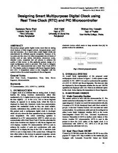
LCD Assembly Types. The most commonly used methods for mounting an LCD's
IC Controller/Driver are COG, COB and TAB type assemblies.
... también por una reclamación mínima nos contactará, VEGA Srl facilita a
continuación la dirección de referencia: VEGA S.r.l.. Mail to: assistenza@vegalift.
it.
Dec 26, 2017 - Voltage range: 5v-20v. Max current: 10amp. 2. Timer wiring diagram. *** For up to date installation instr
Mar 3, 2016 - success in generating controllable advertising performance. Keywords. Feedback ..... tion model as well as to form the ground truth. Similarly,.
the mobile phone (we call it mobile LCD hereafter) to reproduce the same colors as the ..... ply conventional methods to a cellular phone, a Samsung. SCH-500.
with your cable or satellite service provider if you have questions about your cable or ... Welcome to the Panasonic fam
Real Time Clock and LCD Display. Task: Using UP3 Education Kit board
implement a stop-watch timer. Initialize Real Time Clock. (RTC) device and read
...
Real Time Clock and LCD Display Task: Using UP3 Education Kit board implement a stop-watch timer. Initialize Real Time Clock (RTC) device and read seconds value afterwards. Minutes may either be read from RCT as well, or computed based on seconds value. Output seconds and minutes on LCD display. Also incorporate a Reset mechanism, so the stop-watch may be halted and started over. Refer to UP3 manual for pin numbers.
I2C Bus I2C is a two-line, bi-directional serial bus most suitable for short distance communication. It was developed by Phillips in the 1980s, but still remains a widely used mean for data exchange between many devices.
Devices on the I2C bus are organized as Masters and Slaves. To begin communication Master device issues a start sequence. To end transmission Master device sends a stop sequence. Slave devices just respond to these requests. Slave device is selected using a 7-bit address, which is unique for every device connected to the same I2C bus.
Data exchange is made using two wires – SCL (clock line) and SDA (serial data and address line). Master device drives the SCL line to clock each new bit on the SDA line in either direction. Slave device can force a wait by driving the SCL line Low. Before each new clock cycle Master device must ensure the wait condition is not present.
Both SCL and SDA lines are open-drain pulled up with resistors. It means that any device attached to the bus can drive the line Low, but it cannot drive it High. The device releases the line instead to let it float. To implement a bi-directional transmission on SDA line an open-drain buffer must be used. It can be instantiated using the following VHDL code: with data_in select data_out