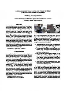
Journal of Imaging Science and Technology® 51(4): 348–359, 2007. © Society for Imaging Science and Technology 2007
Real-Time Color Matching Between Camera and LCD Based on 16-bit Lookup Table Design in Mobile Phone Chang-Hwan Son School of Electrical Engineering and Computer Science, Kyungpook National University, 1370, Sankyuk-dong, Buk-gu, Daegu 702-701, Korea
Cheol-Hee Lee Major of Computer Engineering, Andong National University, 388, Seongcheon-dong, Andong, Gyeongsangbuk-Do 760-747, Korea
Kil-Houm Park and Yeong-Ho Ha䉱 School of Electrical Engineering and Computer Science, Kyungpook National University, 1370, Sankyuk-dong, Buk-gu, Daegu 702-701, Korea E-mail:
[email protected]
Abstract. Based on the concept of multimedia convergence, imaging devices, such as cameras, liquid crystal displays (LCDs), and beam projectors, are now built-in to mobile phones. As such, mobile cameras capture still images or moving pictures, then store them as digital files, making it possible for users to replay moving pictures and review captured still images. Increasingly, users want LCD in the mobile phone (we call it mobile LCD hereafter) to reproduce the same colors as the real scene. Accordingly, this paper proposes a method for color matching between mobile camera and mobile LCD that includes characterizing the mobile camera and mobile LCD, gamut mapping, camera noise reduction, and a 16-bit lookup table (LUT) design. First, to estimate the CIELAB values for the objects in the real scene, mobile camera characterization is achieved through polynomial regression of the optimal order determined by investigating the relation between captured RGB values and measured CIELAB values for a standard color chart. Thereafter, mobile LCD characterization is conducted based on 16-bit/ pixel processing because of the reduced bit depth of the images displayed on a mobile LCD. In addition, a sigmoid model is used to find the luminance value corresponding to the RGB control signal, instead of using gain offset gamma and S-curve models due to the adjustment of luminance curve made by a system designer for preference color reproduction. After completing the two types of characterization, gamut mapping is performed to connect the source medium (mobile camera) with the target medium (mobile LCD), then a combination of sigmoid functions with different parameters to control the shape is applied to the luminance component of the gamut-mapped CIELAB values to reduce camera noise. Finally, a three-dimensional RGB LUT is constructed using 16-bit/ pixel-based data to enable color matching for moving pictures and inserted into the mobile phone. Experimental results show that moving pictures transmitted by a mobile camera can be realistically reproduced on a mobile LCD without any additional computation or memory burden. © 2007 Society for Imaging Science and Technology. 关DOI: 10.2352/J.ImagingSci.Technol.共2007兲51:4共348兲兴
INTRODUCTION With the appearance of multimedia convergence in mobile phones that can now provide such functions as web brows䉱
IS&T Member.
Received Dec. 1, 2006; accepted for publication Mar. 30, 2007. 1062-3701/2007/51共4兲/348/12/$20.00. 348
ing, 3D games, television broadcasting, and image capturing, in addition to communication, manufacturers have invested heavily in super highway communication network, nextgeneration memory chips, and encryption technology for reliable e-commerce operations. The use of color reproduction technology in mobile phones has also been recently introduced to support the development of mobile cameras, mobile beam projectors, and mobile liquid crystal displays (LCDs). In particular, with the rapid increase in mobile cameras, mobile phones can now capture and store still images or moving pictures as digital files, making it possible for users to replay the moving pictures and review captured still images anytime and anywhere. However, mobile LCDs are currently unable to reproduce the original colors captured by a mobile camera due to a reduced bit-depth, lower backlight luminance, and weak resolution.1 In addition, mobile cameras have a small lens, low dynamic range, and poor modulation transfer function (MTF), plus each device senses or displays in a different way, as they have unique characteristics.2 As a result, there is a significant difference in the color appearance when captured images are displayed on a mobile LCD. Therefore, real-time colormatching between mobile camera and mobile LCD in a mobile phone needs to be considered to ensure a better image quality. The aim of color matching is to achieve color consistency even when an image moves across various devices and undergoes many color transformations.3 Several color matching approaches have already been suggested, for example, a simple method is to transmit the RGB digital values from the original device to the reproducing device, referred to as device-dependent color matching. Yet, since this method is no more than physical data transmission, accurate color matching cannot be achieved across various devices. Meanwhile, spectral-based approaches match the spectral reflectance curves of the original and reproduced colors, so the original and reproduction look the same under any il-
Son et al.: Real-time color matching between camera and LCD based on 16-bit lookup table design in mobile phone
Figure 1. The block diagram of the proposed method.
luminant: i.e., there is no metamerism. However, the computation of reflectance is very complex and time consuming, making a spectral-based approach inappropriate for realtime color matching. Another method is colorimetric color matching to reproduce the same CIE chromaticity and relative luminance compared with the original color. This has already been widely applied to imaging devices, such as monitors, printers, and scanners based on the international color consortium (ICC) profile, yet not to mobile phones, which have only been considered as a means of communication until quite recently. However, with multimedia convergence, mobile manufacturers have become aware of the importance of the ICC profile for color matching between mobile cameras and mobile LCDs. Accordingly, this paper presents a real-time color matching system for mobile cameras and mobile LCDs based on the concept of the ICC profile. The proposed color matching system is composed of four steps: Characterization of the mobile LCD and mobile camera, gamut mapping, noise reduction, and a 16-bit-based lookup table (LUT) design. The device characterization defines the relationship between the tristimulus values (CIEXYZ or CIELAB) and RGB digital values. In general, mobile camera characterization is modeled by a polynomial regression, and the more the polynomial order increases, the better the performance. However, for a higher polynomial order, most estimated tristimulus values exceed the boundary of the maximum lightness and chroma, making the implementation of mobile camera characterization difficult, as the relation between the tristimulus values and digital RGB values has not been analyzed. Thus a polynomial order is suggested based on investigating the relation between RGB digital values transformed using the opponent color theory and CIELAB values. Meanwhile, for the mobile LCD characterization, a sigmoid function instead of a conventional method, such as the gain offset gamma (GOG) or J. Imaging Sci. Technol. 51共4兲/Jul.-Aug. 2007
S-curve model, is used to estimate the luminance curve made by the system designer to achieve a preferable color reproduction or to improve the perceived contrast of the mobile LCD. Furthermore, the characterization is conducted based on 16-bit data processing, as a mobile LCD is controlled based on 16-bit data, in contrast to digital TVs or monitors with 24-bit data. After completing the two types of characterization, a gamut-mapping algorithm is applied to connect the source medium (mobile camera) with the target medium (mobile LCD). Although the three processes mentioned above are sufficient to obtain colorimetric color matching for still images, noise reduction and an LUT design still need to be considered to achieve real-time color matching for moving pictures. In a mobile camera, various camera noises, such as CCD noise and thermal noise, are incorporated into moving pictures and further amplified after color matching, thereby degrading the image quality, especially in the dark region of the achromatic axis. Thus, to solve this problem, a combination of two sigmoid functions with different parameters to control the shape is applied to the lightness component of the gamut-mapped tristimulus values to change the contrast ratio. As a result, the lightness values for the camera noise are reduced in the dark region of the achromatic axis, thereby reducing the amplified camera noises. In addition, a three-dimensioinal (3D) RGB LUT is designed based on 16-bit data to reduce the complex computation of serialbased processing and facilitate color matching for moving pictures. PROPOSED METHOD Figure 1 shows a block diagram of the proposed algorithm that can achieve real-time color matching between a mobile camera and a mobile LCD. First, to predict the CIELAB values of arbitrary objects in a real scene, the mobile camera 349
Son et al.: Real-time color matching between camera and LCD based on 16-bit lookup table design in mobile phone
characterization is conducted by finding the relation between the RGB digital values of a standard color chart captured in a lighting booth and CIELAB values measured using a colorimeter. The CIELAB values estimated from the mobile camera characterization of the input RGB values are then transformed into an achievable color range that can be reproduced by the mobile LCD, referred to as gamut mapping. Next, the lightness values of the gamut-mapped CIELAB values are changed using the parameters of a sigmoid function provided by a visual experiment to reduce the camera noise incorporated into a moving picture, then combined with two untouched color signals. Thereafter, the modified gamut-mapped CIELAB values are converted into color matched RGB values for display on the mobile LCD based on a sigmoid-based mobile-LCD characterization to consider the luminance curve adjusted for the preferred color reproduction, along with 16-bit data processing due to the reduced bit depth in the mobile LCD. Finally, a 3D-RGB LUT is constructed using the 16-bit/ pixel-based data to enable color matching for moving pictures and inserted into the mobile phone, thereby allowing 24-bit moving pictures to be reproduced on a mobile LCD with a higher quality image. CHARACTERIZATION OF THE MOBILE LCD BASED ON 16-bit DATA PROCESSING The display characterization predicts the tristimulus value for the input digital value and may be conducted by a measurement-based approach or modeling-based approach.4–6 A measurement-based approach measures a lot of patches made by combination of input digital values using a colorimeter and estimates the tristimulus value by the interpolation method or polynomial regression for an arbitrary digital value. Therefore, this approach improves the characterization accuracy, yet requires a lot of measurement data and extensive memory and is relatively complex. Meanwhile, a modeling-based approach finds the relationship between the digital input data and tristimulus value based on a mathematical function with a smaller number of data measurements. The GOG and S-curve models have been used as typical mathematical functions and have been applied to different types of display. In general, the GOG model is appropriate for CRT display because its electro-optical transfer function, the relationship between the grid voltage and beam current, follows a power curve shape, while LCD display is a binary device that switches from an OFF state to an ON state and follows the S-shaped curve, thereby adapting the S-curve model for LCD characterization. The overall procedure of modeling-based approach is identical except that electro-optical transfer function is modeled with a different mathematical function. The first step of modeling-based characterization is to convert the digital value to luminance value for each RGB channel. This can be done by estimating the coefficient of mathematical function with optimization programming. In the case of the GOG model, mathematical function can be described as 350
冋 冉 冊 册
Ych = kg,ch
dch
␥,ch
+ ko,ch
2N − 1
,
共1兲
where ch represents RGB channel, dch is input digital value, and N is the bit number; 共kg,ch , ko,ch , ␥兲 are the gain, offset, and gamma parameters of the GOG model, respectively. Ych is the normalized luminance value corresponding to the normalized input digital value for each channel. To get all parameters of the GOG model, the digital value of each channel is independently sampled by a uniform M interval, which assumes no channel interaction that the light emitted from a pixel location is dependent only on R, G, B triplet for that pixel and is independent of input digital value for other pixels.7 Then, the CIEXYZ values for M-sample digital values are acquired by measuring the displayed patches created by M-sampled digital values with a colorimeter. At this time, even though displayed patches are made by 8-bit data for each channel, the 8-bit based M-sampled RGB digital values corresponding to the measured CIEXYZ values must be practically converted to 共5 , 6 , 5兲-bit data in the mobile LCD, and thus the digital values of the 8-bit based R-channel and B-channel are divided by 8, while that of the G-channel is divided by 4: dR⬘ =
dR 2
⌬R
,
dG⬘ =
dG 2
⌬G
,
dB⬘ =
dB 2⌬B
,
共2兲
where dR, dG, and dB is the digital value of displayed patch for each channel and 共⌬R , ⌬G , ⌬B兲 is the difference of bitnumber between 8-bit/channel of patches and bit-number/ channel in mobile LCD. Therefore, dch in Eq. (1) is substituted with 共dR⬘ , dG⬘ , dB⬘ 兲, which is used to find the luminance curve of mobile LCD. Of the measured CIEXYZ values, the Y values are selected as Ych, assuming that the shapes of X, Y, and Z are identical after normalization, which is referred to the channel-chromaticity constancy that spectrum of light from a channel has the same basic shape and only undergoes a scaling in amplitude as the digital value for each channel is varied.7 Finally, the pairs of M-sampled digital value 共dR⬘ , dG⬘ , dB⬘ 兲 and Y values are substituted in Eq. (1), yielding all parameters of the GOG model using optimization nonlinear programming. The second step is to transform the luminance value of each channel calculated by the GOG model to the CIEXYZ value. This stage can be simply achieved by a matrix operation:
冤冥 冤 X
Xr,max Xg,max Xb,max
Y = Yr,max Yg,max Yb,max
Z
Zr,max Zg,max Zb,max
冥冤 冥 YR
YG ,
共3兲
YB
where YR, YG, and YB are the luminance values of each channel, Ych=R,G,B. In each column, the matrix coefficients are the CIEXYZ value at the maximum digital value of each channel, and can be directly measured with a colorimeter. Through the above-mentioned two steps, display characterization can be accomplished. In the case of the S-curve J. Imaging Sci. Technol. 51共4兲/Jul.-Aug. 2007
Son et al.: Real-time color matching between camera and LCD based on 16-bit lookup table design in mobile phone
Figure 2. Electro-optical transfer function for mobile LCD; 共a兲 GOG model, 共b兲 GOG model except saturation region, 共c兲 S-curve model, and 共d兲 sigmoid model.
model, only the power-curved function shown in Eq. (1) is replaced with the S-shaped mathematical function in the process of display characterization
冋
Ych = Ach
关dch/共2N − 1兲兴␣ch 关dch/共2N − 1兲兴ch + Cch
册
,
共4兲
where Ach, ␣ch, ch, and Cch are parameters, respectively. Equation (4) has various S-shaped curves according to the parameter values, and if both ch, and Cch is zero, Eq. (4) follows the gamma curve as Eq. (1). All parameters in Eq. (4) can be obtained by applying the same process, the first step explained in the GOG model. Using these parameters, the input digital value is converted into the luminance value and then transformed into the CIEXYZ value through a matrix operation. To conduct the characterization of mobile LCD, we apply conventional methods to a cellular phone, a Samsung SCH-500. In a mobile phone, each RGB pixel value is represented by (5,6,5) bit and image size is fixed at 240⫻ 320. Figures 2(a)–2(c) show the electro-optical transfer function J. Imaging Sci. Technol. 51共4兲/Jul.-Aug. 2007
resulting from the GOG model, the GOG model without the saturation region, and the S-curve model. In Figure 2, three types of lines represent the estimated luminance values obtained by using conventional characterization for each channel, while three types of marks indicate the measured luminance values for each channel. In Fig. 2, the shape of the electro-optical transfer function for mobile display is different from a power-curved shape of CRT display or S-curved shape of LCD display. As the input digital value moves toward the middle point, the gradient of the luminance curve rapidly increases and immediately decreases, producing a saturation region. This is due to the adjustment of the luminance curve by the system designer intended to enhance the contrast ratio and overcome the low channel-bit number. As a result, a conventional GOG model or S-curve model does not follow the luminance curve of the saturation region and is not directly applied to mobile LCD. Therefore, we used the sigmoid function to model the electro-optical transfer function of mobile LCD based on visual observation of the luminance curve. The sigmoid function is expressed as 351
Son et al.: Real-time color matching between camera and LCD based on 16-bit lookup table design in mobile phone
Table I. Estimated parameter of sigmoid function. a-parameter
c-parameter
R-channel
11.9149
0.4647
G-channel
11.1892
0.4508
B-channel
11.3273
0.4359
Table II. Performance of mobile LCD characterization with various methods. * Average Eab
* Maximum Eab
GOG model
15.655
32.4424
GOG model except saturation region
8.7614
17.5898
S-curve model
6.9801
15.2279
Sigmoid model
3.9683
14.6831
1 sigmoid共x,a,c兲 =
1 + exp关− a共x − c兲兴
.
共5兲
The sigmoid function is a symmetrical function with respect to c and is a constant value if it is zero. The shape of a sigmoid function depends on the absolute value of a, and as the absolute value of a increases, the gradient of the sigmoid function rapidly increases with respect to c. Figure 2(d) shows the electro-optical transfer function resulting from the sigmoid model. In Fig. 2(d), the estimated luminance curve closely follows the measured luminance value and it is predicted that the estimation error will be reduced. The estimated coefficients of the sigmoid function are shown in Table I. The estimated curve is nearly symmetric with respect to 0.45 and the absolute value of a to determine the shape of the sigmoid function is independent of channel and is almost the same.
To evaluate the performance of each method, the * CIE1976 color difference 共⌬Eab 兲 was used to measure the characterization error, which is the Euclidian distance between estimated CIELAB value and measured CIELAB value. Sixty-four patches were tested and Table II shows the characterization error of various model-based methods. The GOG model had the largest color difference and the characterization error was still severe although the GOG model was used except in the saturation region. For the S-curve model, * was approximately 6.9 and is normal color the average ⌬Eab difference. However, in the middle region, the estimated luminance value shows a significant difference compared with measured luminance value. The sigmoid model has a good average color difference smaller than 6.0, which is indistinguishable in human vision. DECISION OF POLYNOMIAL ORDER FOR THE CHARACTERIZATION OF MOBILE CAMERA The camera characterization is to find the relationship between the tristimulus value and digital RGB value. Through the accurate camera characterization, we can get information about an object color in real scene and reproduce the object color on mobile LCD. The general procedure of camera characterization is shown in Figure 3. First, a standard color chart such as a Macbeth or Gretag Color Chart is placed with 0 / 45° geometry in a lighting booth, where an illuminant is set at D65 to reflect the perceived color corresponding to a daylight condition.8 The standard color chart is then captured by a mobile camera set with autofocusing to avoid color clipping. Captured RGB digital values of each patch in the standard color chart are averaged to reduce the camera noise and nonuniformity of illumination. Next, the tristimulus value of the standard color chart is acquired by measuring each patch of the color chart or standard data provided by the manufacturer. Finally, polynomial regression with least square fitting is applied to find the relationship between captured RGB digital values and measured tristimulus values.9,10 In general, the performance of camera characterization becomes better as the polynomial order increases. Practically,
Figure 3. The procedure for mobile camera characterization. 352
J. Imaging Sci. Technol. 51共4兲/Jul.-Aug. 2007
Son et al.: Real-time color matching between camera and LCD based on 16-bit lookup table design in mobile phone
Figure 4. The characteristics of cellular camera; 共a兲 L* vs average RGB value of gray sample, 共b兲 a* vs 共R − B兲, and b* vs 共G − B兲.
Figure 5. The characteristics of PDA camera; 共a兲 L* vs average RGB value of gray sample, 共b兲 a* vs 共R − B兲, and b* vs 共G − B兲.
for a higher polynomial order, most estimated tristimulus values exceed the boundary of the maximum lightness and chroma, and there is difficulty in implementing mobile camera characterization. This is because the characteristic curve of the mobile camera, i.e., the relationship between the tristimulus value and digital RGB value, is not analyzed to suggest an appropriate polynomial order. To determine the polynomial order, the RGB digital value is manipulated based on opponent color theory and is compared with the
CIELAB value. The CIELAB space is an opponent color coordinate composed of a lightness signal and two types of color signals obtained by the difference of three color signals. Thus the RGB digital value is transformed into a lightness signal and two color signals, 共R + G + B兲 / 3, 共R − B兲, and 共G − B兲, just as in opponent color space. Figures 4 and 5 show the relationship between the manipulated RGB values and CIELAB values for a cellular camera and PDA camera. From a visual evaluation, the distribution of the measure-
J. Imaging Sci. Technol. 51共4兲/Jul.-Aug. 2007
353
Son et al.: Real-time color matching between camera and LCD based on 16-bit lookup table design in mobile phone
ment data was found to be slightly dispersed due to nonuniform illumination intensities according to the spatial position on the color chart, where the lux-meter measurements for the four corners were 1990 lux, 2055 lux, 1955 lux, and 1922 lux, respectively. Although efforts were made to correct the nonuniformity of the illumination intensity, the modeling of lux-meter measurements according to their distance from the center of the color chart is not trivial work due to their random distribution, therefore, this issue has been carried over to future work. However, it was still clear that the manipulated RGB digital values were roughly linear to the CIELAB values:
冉
R+G+B 3
冊
⬀ L *,
共R − B兲 ⬀ a*,
共G − B兲 ⬀ b* . 共6兲
Therefore, a first-order polynomial is adopted, and mathematical modeling of mobile camera characterization is expressed as linear equations: L* = 1 + ␣L,RR + ␣L,GG + ␣L,BB,
Table III. Estimation errors of mobile camera characterization. * Average Eab
* Maximum Eab
Cellular camera 共Samsung SCH-100兲
4.3605
12.2098
PDA camera 共Samsung SPH-M400兲
6.2638
16.8828
* L* = L* − 共Lmax − 100兲, * , a*⬘ = k ⫻ a*/amax
b*⬘ = b*/a* ⫻ a*⬘ ,
共10兲 共11兲
where k is the constant value for color-signal compression. Lmax and amax are the estimated maximum lightness value and color signal value, respectively. Table III shows the performance of mobile camera characterization for the color chart; the PDA camera shows poorer performance than the cellular camera. When observing the moving picture transmitted from the mobile camera, the PDA camera is subject to more noise than the cellular camera, which will produce a large characterization error.
a* = 1 + ␣a,RR + ␣a,GG + ␣a,BB, b = 1 + ␣b,RR + ␣b,GG + ␣b,BB.
共7兲
*
Equation (7) can be equally expressed in vector form, P = V T␣ ,
冤 冥 冤 冤 冥 11, . . . ,1n
V=
R 1, . . . R n
,
G 1, . . . G n
␣=
B 1, . . . B n
␣L,1 , ␣a,1 , ␣b,1 ␣L,2 , ␣a,2 , ␣b,2 ␣L,3 , ␣a,3 , ␣b,3 ␣L,4 , ␣a,4 , ␣b,4
冥
,
共8兲
L1* , a1* , b1*
P=
·
·
·
·
·
·
,
Ln* , an* , bn*
where n is the patch number of color chart. The ultimate goal of mobile camera characterization is deriving the coefficients of the linear equation, which can be obtained by pseudoinverse transformation of Eq. (8):
␣ = 共VVT兲−1VP.
共9兲
Using the derived coefficients, an arbitrary captured digital value can be converted into the CIELAB value. However, some of the estimated CIELAB values may exceed the maximum value of CIELAB space caused by the error of linear regression. To solve this problem, the lightness value is subtracted from the amount of excessive lightness, and two color signals are linearly compressed while preserving their hue value: 354
REAL-TIME COLOR MATCHING BETWEEN MOBILE CAMERA AND MOBILE LCD BASED ON 16-bit LUT DESIGN INCLUDING NOISE REDUCTION The process of colorimetric color matching reproduces the same CIE chromaticity and relative luminance compared with the original color, and has been widely applied to imaging devices such as monitors, printers, and scanners based on the ICC profile, but not to mobile phones because mobile phones have been considered to be primarily communication devices. However, with multimedia convergence, mobile manufacturers have become aware of the necessity of color matching between mobile camera and mobile LCD. With the characterization of mobile camera and mobile LCD, to implement the color matching system, achievable ranges of colors (gamut) must be considered. Figure 6 shows the gamut difference between a mobile camera under D65 environment (point) and a mobile LCD (solid color). As shown in Fig. 6, the gamut of mobile camera is larger than that of mobile LCD, and has a regular form resulting from the use of linear equations. Thus, significant parts of the mobile camera gamut can be unachievable by the gamut of mobile LCD, and it is necessary to alter the original colors (mobile camera) to ones that a given output medium (mobile LCD) is capable of reproducing. This power is frequently referred to as gamut mapping. In this paper, gamut mapping with variable and multiple anchor points is used to reduce any sudden color changes on the gamut region boundary and increase the lightness range reduced in conventional gamut mapping toward an anchor point.11 In general, the performance of colorimetric color matching between cross media, such as a monitor and printer, depends on the gamut mapping and device characterization. However, in the case of a mobile camera, various camera noises, such as CCD noise and thermal noise, can be J. Imaging Sci. Technol. 51共4兲/Jul.-Aug. 2007
Son et al.: Real-time color matching between camera and LCD based on 16-bit lookup table design in mobile phone
Figure 6. Gamut mismatches between mobile camera 共point兲 and mobile LCD 共solid color兲; 共a兲 projected to 共a* , b*兲 plane and 共b兲 projected to 共L* , b*兲 plane.
included in moving pictures and become amplified after color matching, especially in the dark regions of the achromatic axis, although not in the chromatic region due to the blending of the reproduced signal. To solve this problem, the combination of two sigmoid functions with different parameters is applied to the lightness component of gamutmapped tristimulus values to change the contrast ratio. The sigmoid function is expressed as n=i
Si = 兺
n=0
1
冑2
e−关100xn/共m − x0兲
2/共2⌺2兲兴
,
i = 1,2, . . ,m, 共12兲
SLUT =
关Si − min共S兲兴 关max共S兲 − min共S兲兴
* * * 共Lmax out − Lmin out兲 + Lmin out .
共13兲 Equation (12) is a discrete cumulative normal function 共S兲, where x0 and ⌺ are the mean and standard deviation of the normal distribution, respectively, and m is the number of points used in the discrete lookup table. Xn is the gamutmapped lightness component of CIELAB values and this value is then scaled into dynamic range of the mobile LCD, * * as given in Eq. (13), where Lmin out and Lmax out are blackpoint and white-point lightness value of the mobile LCD. In Eq. (12), x0 controls the centering of the sigmoid function, J. Imaging Sci. Technol. 51共4兲/Jul.-Aug. 2007
Figure 7. Modified sigmoid function for noise reduction; 共a兲 sigmoid functions with different parameters and 共b兲 the combination of two sigmoid functions.
and ⌺ controls the shape. To find the parameters to conceal the camera noise through the lightness remapping, visual experiments were repeated based on adjustment of two parameters, and thus we found that the combination of two sigmoid functions is needed. In Figure 7(a), the solid line with x0 = 30 and ⌺ = 11.025 is the optimal curve to reduce the camera noise in the dark region, yet remapped lightness values in the bright region are significantly increased, forming a saturation region. Thus another sigmoid function with x0 = 40 and ⌺ = 27.35, represented by dotted line in Fig. 7(a), is applied to the gamut-mapped light values larger than the input lightness value of 20 in order to make the lightness value of the reproduced image similar to that of the original image. Ultimately, the combination of two sigmoid functions, as shown in Fig. 7(b) expressed by the solid line, decreases the lightness value of camera noise in the dark region of achromatic axis, and from this result, amplified camera noise is hardly observed by a human eye. This kind of serial processing mentioned above, including the characterization, gamut mapping, and noise reduc355
Son et al.: Real-time color matching between camera and LCD based on 16-bit lookup table design in mobile phone
Table IV. Example of bit quantization.
Table V. The example of proposed 3D-RGB LUT.
6-bit quantization
8-bit input data && 8-bit masking data
R
G
B
R⬘
G⬘
B⬘
R-channel: 共00110兲
共00110011兲 && 共11111000兲
26
64
0
24
64
17
G-channel: 共011001兲
共01100110兲 && 共11111100兲
32
64
0
25
64
18
B-channel: 共10011兲
共10011001兲 && 共11111000兲
0
0
6
3
3
4
tion, has computational complexity and is not appropriate for real-time processing. Therefore, a 3D-RGB LUT is constructed based on N-grid points for each channel. The input RGB digital values are uniformly sampled by n ⫻ n ⫻ n grid points, which are processed by serial color matching, resulting in new corresponding output RGB values. The input RGB digital value and output RGB digital values are stored in the 3D-LUT and arbitrary input RGB values are calculated by interpolation. This 3D-LUT can be inserted into the mobile LCD without any difficulties associated with memory and computation. In actuality, in a mobile phone, a moving picture has 8-bits per channel, while the displayed RGB image on the LCD screen is represented by 共5 , 6 , 5兲 bits per channel. Thus, before displaying an image on the LCD screen, 24-bit moving picture data is quantized into 16-bit data through a bit operation used in program language. For
6
0
6
10
3
2
13
0
6
14
0
1
19
0
6
17
0
1
26
0
6
21
0
3
32
0
6
23
0
4
0
13
6
0
19
4
example, suppose that the moving picture data to be displayed is (51,102,153). The final data are calculated by applying the AND operation (&&) with 8-bit masking data. Table IV shows an example of the AND operation. EXPERIMENTS AND RESULTS To conduct a subjective experiment of colorimetric color matching, test images were captured using a mobile camera; these included both face image and color chart images cap-
Figure 8. The experimental results with the cellular phone; 共a兲 and 共b兲 device-dependent color matching, 共c兲 and 共d兲 proposed color matching. 356
J. Imaging Sci. Technol. 51共4兲/Jul.-Aug. 2007
Son et al.: Real-time color matching between camera and LCD based on 16-bit lookup table design in mobile phone
Figure 9. The experimental results with the PDA camera; 共a兲 and 共b兲 device-dependent color matching, 共c兲 and 共d兲 proposed color matching.
tured in a lighting booth with D65 illumination. Statistically, the face image is one of the most frequently captured images, and people are very sensitive to their skin color displayed on mobile LCD. For this reason, a face image representing the skin color was selected as a test image. Similarly, the reason why the color chart image captured under D65 illumination was used as a test image was that the characterization of the mobile camera was conducted under D65 illumination, and subjective performance of color matching can be easily evaluated by comparing the displayed image with the real object as seen in the lighting booth. In addition, device-dependent color matching was compared to evaluate the performance of colorimetric color matching. Device-dependent color matching directly transmits the captured image to mobile LCD, while colorimetric color matching sends the captured image through the 3D-RGB LUT, J. Imaging Sci. Technol. 51共4兲/Jul.-Aug. 2007
which is quantized and transmitted to the mobile LCD. Table V shows a part of the data set stored in the 3D-RGB LUT designed to the 16-bit system. In the R channel and B channel, the maximum digital value is 25, whereas G-channel’s maximum digital value is 26. Based on the 16-bit LUT, colorimetric color matching between mobile camera and mobile LCD can be processed in real time. SUBJECTIVE EXPERIMENT OF DEVELOPED COLOR MATCHING BASED ON 16-bit LUT DESIGN Figure 8 shows the captured images that are displayed on the cellular phone. Figures 8(a) and 8(b) show the images resulting from device-dependent color matching, while Figs. 8(c) and 8(d) show the images resulting from LUT-based colorimetric color matching. In Fig. 8(a), even though the picture is taken against the light, the face region is very 357
Son et al.: Real-time color matching between camera and LCD based on 16-bit lookup table design in mobile phone
Figure 11. Quality evaluations of device-dependent color matching and proposed color matching.
seen in the D65 daylight, especially the red and green hues. Figure 9 shows the results of color matching for a PDA phone; the same effect is shown. Figure 10 shows the resulting images of colorimetric color matching considering the noise reduction. Figure 10(a) is the resulting image obtained by conventional colorimetric color matching, and its image quality is significantly degraded by the camera noise. By applying the combination of two sigmoid functions in Fig. 7(b) to conventional colorimetric matching, the contrast ratio of reproduced image is changed and from this result, camera noise is not observable to the human eye, as shown in Fig. 10(b). Consequently, color matching based on 3DLUT accurately reproduces the object color seen in the real scene and thus improves the color fidelity of the mobile display. For moving pictures, the same results decreasing the camera noise can be achieved with no problems of computation and memory.
Figure 10. The results of noise reduction; 共a兲 before lightness remapping and 共b兲 after lightness remapping.
bright due to the tendency of the electro-optical transfer function of mobile LCD to saturate the bright region as shown. In addition, the colorfulness of “table” and “cloth” region is more decreased than the original color, and the image quality is degraded. As shown in Fig. 8(c), the skin color in the “face” region is more natural and realistic than in Fig. 8(a), and the object colors such as “cloth” and “table” are well reproduced on LCD. For the Macbeth Color chart seen in Fig. 8(b), colors of each patch are washed out and exhibit major differences in appearance, compared with original color seen in the D65 lighting booth, because device-dependent color matching is only physical data transmission. On the other hand, the result shown in Fig. 8(d) adquately represents the colorfulness of the original color 358
QUANTITATIVE EVALUATION OF THE DEVELOPED COLOR MATCHING To evaluate colorimetric color matching based on 16-bit RGB LUT, a Macbeth Color Chart composed of 24 patches was used as a test image. For quantitative evaluation of the device dependent color matching, the Macbeth Color Chart is previously captured in the D65 lighting booth, and is displayed on mobile LCD. Then, the CIELAB value of each patch is measured using a colorimeter and compared with the CIELAB data of the Macbeth Color Chart measured in the D65 lighting booth, thus calculating the CIE 1976 color difference. For the proposed color matching, the Macbeth Color Chart is again captured in the D65 lighting booth, and is displayed on mobile LCD through use of the 16-bit RGB LUT. Then, the CIELAB value of each patch is measured using a colorimeter and compared with the CIELAB data of Macbeth Color Chart measured in the D65 lighting booth. Figure 11 shows the result of quantitative evaluation using 1976 Color difference. In Fig. 11, several patches corresponding to the proposed color matching have a larger color difference than for the conventional method, due to the characterization errors of the mobile camera and mobile LCD. However, the proposed color matching has a lower average color difference of 15.56, whereas device-dependent color matching has the average color difference of 24.395. J. Imaging Sci. Technol. 51共4兲/Jul.-Aug. 2007
Son et al.: Real-time color matching between camera and LCD based on 16-bit lookup table design in mobile phone
Therefore, the proposed color matching achieves better colorimetric reproduction than the conventional method, and it is concluded that object color transmitted by mobile camera in real time can be accurately and realistically reproduced on a mobile LCD. CONCLUSIONS This paper presented a method for real-time color matching between mobile camera and mobile LCD, involving characterization of the mobile camera and mobile LCD, gamut mapping, noise reduction, and a LUT design. The characterization of the mobile LCD is conducted based on 16-bit processing, plus a sigmoid function is used to estimate the electro-optical transfer function. Meanwhile, for the characterization of the mobile camera, the optimal polynomial order is determined by transforming the captured RGB data into opponent color space and finding the relationship between the transformed RGB values and the measured CIELAB values. Following the two types of characterization, gamut mapping is executed to overcome the gamut difference between the mobile camera and the mobile LCD, then noise reduction processing is applied to the lightness component of the gamut-mapped CIELAB values. Finally, to reduce the complex computation of serial-based color matching, a 3D RGB LUT is designed based on 16-bit data and inserted into the mobile phone. Experiments demonstrated that the proposed color matching realistically reproduced object colors from a real scene on a mobile LCD and improved the fidelity color of the mobile display. The LUT was also designed without any further computation or memory burden, making real-time processing possible.
J. Imaging Sci. Technol. 51共4兲/Jul.-Aug. 2007
Acknowledgments This work is financially supported by the Ministry of Education and Human Resources Development (MOE), the Ministry of Commerce, Industry and Energy (MOCIE), and the Ministry of Labor (MOLAB) through the fostering project of the Lab of Excellency. REFERENCES 1
J. Luo, “Displaying images on mobile device: capabilities, issues, and solutions”, Wirel. Commun. Mob. Comput. 2, 585–594 (2002). 2 J. Y. Hardeberg, Acquisition and reproduction of color images: colorimetric and multispectral approaches, Universal Publishers, Dissertation.com, 2001. 3 H. R. Kang, Color Technology for Electronic Image Device (SPIE Optical Engineering Press, Bellingham, WA, 1996). 4 R. S. Berns, “Methods for characterizing CRT displays”, Displays 16, 173–182 (1996). 5 Y. S. Kwak and L. W. MacDonald, “Characterisation of a desktop LCD projector”, Displays 21, 179–194 (2000). 6 N. Tamura, N. Tusmura, and Y. Miyake, “Masking model for accurate colorimetric characterization of LCD”, Proc. IS&T/SID Tenth Color Imaging Conference (IS&T, Jmigtiel, VA, 2002), 312–316. 7 G. Sharma, “LCD versus CRTs color-calibration and gamut consideration”, Proc. IEEE 90, 605–622 (2002). 8 M. D. Fairchild, Color Appearance Models (Addison-Wesley, Reading, MA, 1998). 9 G. Hong, M. R. Luo, and P. A. Ronnier, “A study of digital camera colorimetric characterization based on polynomial modeling”, Color Res. Appl. 26, 76–84 (2001). 10 M. R. Pointer, G. G. Attridge, and R. E. Jacobson, “Practical camera characterization for colour measurement”, Imaging Sci. J., 49, 63–80 (2001). 11 C. S. Lee, Y. W. Park, S. J. Cho, and Y. H. Ha, “Gamut mapping algorithm using lightness mapping and multiple anchor points for linear tone and maximum chroma reproduction”, J. Imaging Sci. Technol. 45, 209–223 (2001).
359